Evaluation of the pressure-resistance of the intersection of a Membrane-type primary barrier: part 2 finite element analysis
Copyright ⓒ The Korean Society of Marine Engineering
This is an Open Access article distributed under the terms of the Creative Commons Attribution Non-Commercial License (http://creativecommons.org/licenses/by-nc/3.0), which permits unrestricted non-commercial use, distribution, and reproduction in any medium, provided the original work is properly cited.
Abstract
Hydraulic pressure tests were performed using an apparatus developed to simulate large compressive loads acting on the outer wall of a membrane-type primary barrier. However, the precise processing required to fabricate the complex intersecting corrugations on the test sample limits the number of test samples that could be produced, and thus performing tests under a variety of pressure-range conditions is impractical. The aims of this study were to conduct hydraulic pressure tests using the finite element method and to propose a design support methodology validated by the experimental results. Surface data were extracted using an optical three-dimensional scanner to analyze the complex geometry of the intersection, and quasi-static tensile test data for the primary barrier material were used to describe the plastic behavior. The finite element analysis results confirmed that the von Mises equivalent stress significantly increased within the tested pressure range, which indicated increased plastic deformation and decreased load-bearing capacity.
Keywords:
Primary barrier, Finite element analysis, Validation, Design support methodology, von Mises equivalent stress1. Introduction
The recent expansion of the capacity of liquefied natural gas (LNG) carriers has increased the hydrodynamic loads experienced by the LNG cargo, which in turn impose significant compressive loads on the exterior membrane-type primary barrier walls that are typically used to seal LNG [1]. These walls also experience remarkable thermal shrinkage strain in response to the low-temperature environment [2]. The membrane-type primary barrier is made of thin plates of cryogenic 304L stainless steel (STS304L) with preformed corrugations to prevent thermal shrinkage strain. The thermal strain is instead experienced by the corrugations, which lowers the in-plane stiffness of the barrier and effectively prevents structural damage to the thin metal plates [3]. Considering the above, membrane-type primary barriers must be designed not only to offset the thermal strain stress in a cryogenic environment, but also to withstand external pressure. Several studies have been conducted to simulate damage to membrane-type primary barriers and to develop design support methodologies for simulation purposes. Kim et al. [4] studied the tensile load applied on the primary barrier due to hogging and sagging during sailing via experiments and finite element analysis. They developed an experimentally validated design support methodology based on constitutive relations describing the plastic behavior of the primary barrier materials. Kim et al. [5] evaluated the impulsive load imposed on the primary barrier due to the sloshing of LNG during sailing through experiments and finite element analysis. Subsequently, they developed a design support methodology satisfying the failure criterion associated with the ductile characteristics of primary barrier metals related to necking, ductility, and shear. In this study, a custom-designed hydraulic pressure test apparatus was operated to simulate the compressive load induced by the hydrodynamic LNG load. However, the precise processing required to form the complex geometry of the intersection during the fabrication of test specimens limits the number of hydraulic pressure tests under various pressures that can feasibly be performed. To address this limitation, the finite element method has been employed to model to simulate the developed hydraulic pressure test, and a design support methodology has been proposed and experimentally validated. Moreover, the structural vulnerabilities of the primary barrier intersection and its pressure-resistance have been assessed through von Mises equivalent stress analysis.
2. Finite Element Analysis
2.1 Material modeling
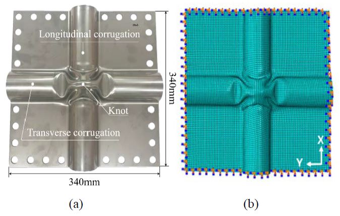
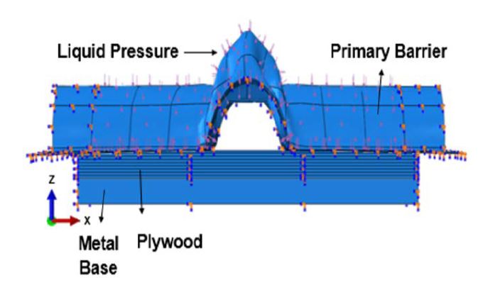
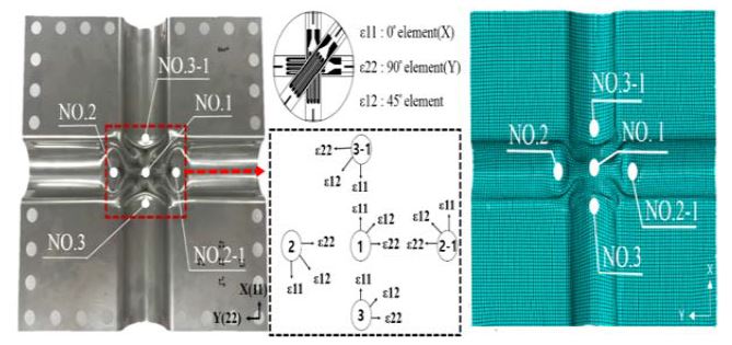
In this study, a membrane-type primary barrier was evaluated using finite element analysis. The test specimen was fabricated using a 1.2 mm thick (T) plate of isotropic cryogenic STS304L with corrugations to avoid thermal shrinkage strain. The specimen dimensions were 340 mm (W) × 340 mm (B). The transverse corrugation (Y) and the longitudinal corrugation (X) intersected each other at a 90°angle; Figure 1 (a) shows a photograph of the test specimen. The geometry of the corrugation intersection was extracted using an optical 3D scanner to model the surface geometry data as shown in Figure 1 (b). The laminated plywood and metal base underneath the primary barrier test specimen were modeled as shown in Figure 2 to replicate the experimental setup.
2.2 Material properties
The hydraulic pressure test to simulate the hydrodynamic load in this study was analyzed using the quasi-static tensile profile for STS304L [6]. The Young’s modulus and yield strength were obtained through the 0.2% offset method [7], and Figure 3 shows the obtained elastic region for STS304L.
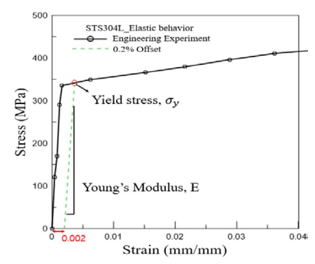
Determination of the elastic region of STS304L from the material stress–strain curve using the 0.2% offset method
The membrane-type primary barrier and steel plate materials were isotropic, whereas the laminated plywood was composed of normal anisotropic materials. The laminated plywood and steel plate did not exhibit notable permanent strain after the hydraulic pressure tests. Table 1 summarizes the physical properties of each material in the elastic region utilized in the finite element analysis.
The test specimen experienced permanent strain after the hydraulic pressure tests; hence, its plastic behavior beyond the yield point must be considered. The membrane-type primary barrier was made of ductile STS304L, the plastic behavior of which follows the Ramberg–Osgood Equation [8]. The plastic deformation associated with the Ramberg–Osgood equation is given as follows:
| (1) |
In Equation (1), E is the Young’s modulus of the material, σ0 is the yield strength, N is the strain hardening, and α is the non-dimensional material constant. Here, the material constant associated with the Ramberg–Osgood equation is given by:
| (2) |
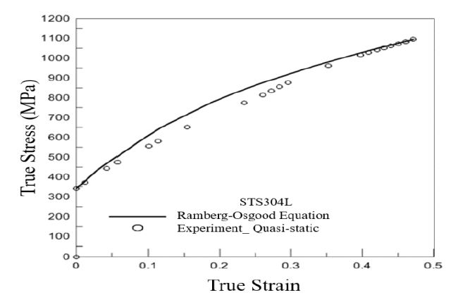
In Equation (3), H and n(1/N) are material constants while ϵyp is the constant offset. To estimate the material constants for the test specimen in this study, the stress–strain data from the STS304L quasi-static tensile test were fitted using the Ramberg–Osgood equation, as depicted in Figure 4. Table 2 lists the properties of the primary barrier material.
| (3) |
The finite element analysis used the Ramberg–Osgood-equation-based deformation plasticity model for the plastic analysis of ductile metals [8]. The deformation plasticity model employed in the analysis was:
| (4) |
In Equation (4), I is the unit vector and S is the deviator stress expressed as S=σ+pI ; P is the equivalent hydraulic pressure stress given as ; and q is the von Mises equivalent stress defined as . The deformation plasticity model fully simulates the plastic behavior beyond the yield point in the elastic region and iterates until the following condition is satisfied:
| (5) |
2.3 Finite element analysis conditions
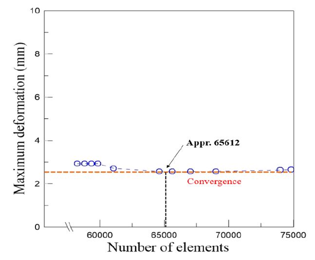
The finite element model was designed to correspond to the experimental hydraulic pressure tests used for verification. Loads of 1.8 MPa, 2.2 MPa, and 2.6 MPa were imposed, which corresponded to those applied in the experimental hydraulic pressure test. The magnitude of the pressure was varied to simulate 3 min at maximum pressure and the pressure relief period. Dynamic-implicit finite element analysis was conducted considering the fluid pressure. The contact conditions were chosen based on the layered structure of the hydraulic pressure test equipment. Subsequently, surface-to-surface contact was applied to each material; the friction coefficient between the primary barrier and laminated plywood was set to 0.1 in the finite element analysis [9]. The meshes were discretized using a reduced-integration-type element (eight-node bricks, C3D8R) to overcome the locking effect associated with the intersection geometry. The optimal number of elements was determined based on the grid convergence at the maximum pressure of 2.6 MPa. The primary barrier, laminated plywood, and steel plate featured 10161, 40328, and 15123 elements, respectively, when convergence was achieved, giving a total of 65612 elements. The size of the mesh elements was approximately 0.8 mm. Figure 5 shows the convergence of the displacement as the mesh evolved toward the optimal number of grid elements, and Table 3 lists the conditions used in the present finite element analysis.
3. Results of the Analysis and Evaluation
3.1 Validation
The finite element model formulated in this work was validated against the local principal strain histories obtained from experimental hydraulic pressure tests. The principal strain was measured using a three-axis rosette strain gauge manufactured by Tokyo Measurement Laboratory (TML), and its history was obtained using the principal strain formulae provided by the company [10]. The principal strain history was numerically evaluated at the locations of the strain gauges in the hydraulic pressure test, which are indicated in Figure 6.
Figure 7 depicts the experimental and numerical time-strain relationships at the primary barrier intersection at different hydraulic pressures. The histories obtained from the finite element analysis and hydraulic pressure test were in good agreement. A minute discrepancy was introduced in the principal strain history due to the initial plastic deformation during the fabrication of the test specimen, which was not accounted for by the model. During the initial plastic deformation, phase transition from austenite to martensite occurs, which causes strain hardening as the yield strength increases [4]. The experimental results verified the suitability of this design support methodology for hydraulic pressure tests.
3.2 von Mises equivalent stress
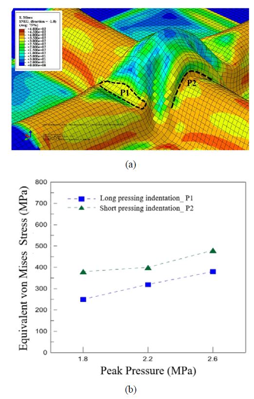
The finite element method was then employed to analyze the von Mises equivalent stress at the corrugation intersection. Figure 8 (a) shows the von Mises equivalent stress distribution at the intersection under the maximum pressure of 2.6 MPa. The von Mises equivalent stress represents the maximum distortion energy at each point of an object subject to a weight. The von Mises yield condition implies that plasticity occurs when the computed equivalent stress becomes greater than the material yield strength, which was 336.91 MPa in this study; it is considered to be the most accurate fault condition. P1 and P2 (Figure 8 (a)) represent the long pressing indentation of the preformed intersection, while P2 represents the short pressing indentation. Figure 8 (b) shows the von Mises equivalent stress as a function of pressure at P1 and P2. As shown in the figure, P2 reaches an equivalent stress greater than the material yield strength at the lowest pressure of 1.8 MPa, and its value is approximately 100% higher than that of P1. In the case of P1, the equivalent stress becomes greater than the material yield strength between 2.2 MPa and 2.6 MPa; thus, plastic deformation would be anticipated to occur between 2.2 MPa and 2.6 MPa according to the von Mises yield condition.
3.3 Structural vulnerabilities
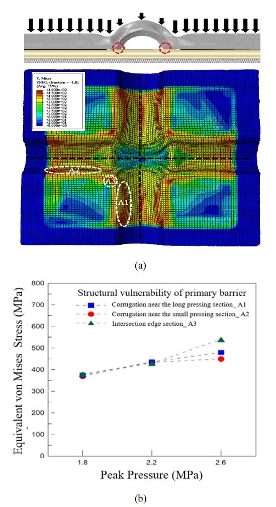
The structural vulnerabilities of the primary barrier were identified under the maximum-pressure environment using the von Mises equivalent stress distribution, and its pressure-resistance capability was evaluated based on these data. Figure 9 (a) depicts the equivalent von Mises stress distribution for the primary barrier test specimen under the maximum pressure of 2.6 MPa. The locations with the maximum equivalent stress values were determined; these structurally vulnerable regions are indicated as A1, A2, and A3 in the figure. A1 represents the structurally vulnerable region of the corrugation near the short pressing indentation, A2 indicates that near the long pressing indentation, and A3 denotes that near the edge of the intersection. Figure 9 (b) shows the von Mises equivalent stress at A1, A2, and A3 with respect to the applied pressure. At the lowest pressure (1.8 MPa), the equivalent stress was similar in all the vulnerable regions and was greater than the material yield strength. Similar increases in all the values were observed at 2.2 MPa. Between 2.2 MPa and 2.6 MPa, however, the equivalent stresses of the three regions began to deviate. In particular, the equivalent stress at A3 increased quickly due to rapid plastic deformation, and its load-bearing capacity was lost. The equivalent stress increase rate was the greatest for A3 and reached its maximum value at 2.6 MPa. The equivalent stress was concentrated at A3, as also demonstrated by the fact that this region of the corrugation intersection sagged under pressure in the experimental hydraulic pressure test. The equivalent stress increase rate at A1 was greater than that at A2, as more plastic deformation occurred at A1 than A2. The long pressing indentation in A2 acts as a support for nearby corrugations, preventing plastic deformation [11].
3.4 Intersection thickness distribution
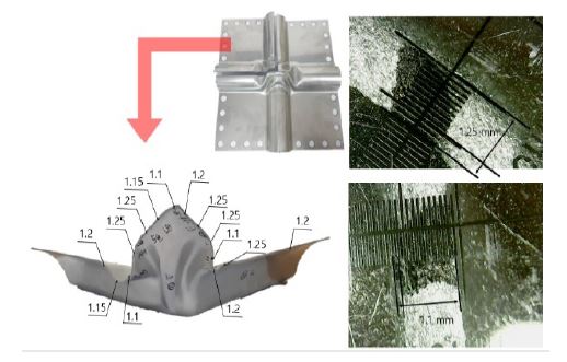
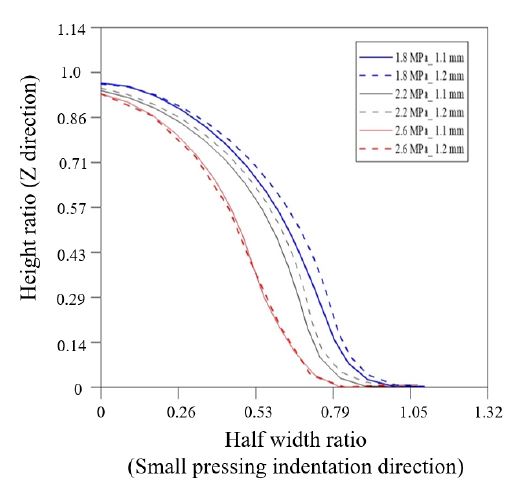
The thickness distribution of the intersection of the membrane-type primary barrier was measured using high-pressure water jet cutting. While the primary barrier sheet was fabricated from a metal sheet with a thickness of 1.2 mm, the intersection thickness distribution varied from 1.1 mm to 1.25 mm, as depicted in Figure 10. The simple bending process during the formation of a membrane-type primary barrier must a ensure uniform thickness with a ±10% tolerance [12]; the observed values were within this tolerance. For increased credibility, an additional finite element analysis was conducted using a model with a minimum thickness of 1.1 mm, and exhibited a corrugation strain history similar to that of the 1.2 mm model, as shown in Figure 11.
4. Conclusion
The present study comprised finite element analysis of a membrane-type primary barrier intersection and experimental validation of a design support methodology for hydraulic pressure tests. Subsequently, the pressure-resistance of the intersection was evaluated. The results can be summarized as follows:
- • The experimental and numerical time–strain relationships asa function of pressure were compared in this work, and theprincipal strain histories determined using the two methodswere found to be in good agreement.
- • The von Mises equivalent stress at the intersection was analyzed using the finite element method. The equivalent stressat P2, which was located on the short pressing indentation,was greater than the material yield strength at even the lowestpressure of 1.8 MPa, whereas that at P1, which was located on the long pressing indentation, first exceeded the material yield strength at a pressure between 2.2 MPa and 2.6 MPa. Thus,plastic deformation occurs between 2.2 MPa and 2.6 MPa according to the von Mises yield condition.
- • The most structurally vulnerable regions were identified fromthe von Mises equivalent stress distribution under the maximum pressure, and the pressure-resistance capability wasevaluated accordingly. All the vulnerable regions exhibitedsimilar equivalent stress values that were above the yieldstrength at the initial pressure, but the rates of increase in their equivalent stress values diverged between 2.2 MPa and 2.6MPa. In particular, the equivalent stress at A3, which was located near the corner of the intersection, increased rapidly between 2.2 MPa to 2.6 MPa due to rapid plastic deformation,and this region lost its load-bearing capacity.
- • To increase the credibility of the finite element analysis, anadditional finite element analysis was performed using theminimum thickness of 1.1 mm. The resulting strain historywas in good agreement with that obtained using a thickness of 1.2 mm.
The principal strain values obtained experimentally and nu-merically differed slightly, as the model did not account for the strain hardening induced by the initial plastic deformation during test specimen fabrication. Further studies are thus needed to address this discrepancy.
Acknowledgments
This material is based upon research supported by or supported, in part, by the National Research Foundation of Korea through the Ministry of Science and ICT (Grant No. 2018R1A2B6007403) and a Korea Evaluation Institute of Industrial Technology 019 research grant (Grant No. 20006644).
Author Contributions
Conceptualization, Y. J. Jeong; methodology, Y. J. Jeong and H. T. Kim; Software, Y. J. Jeong; Formal Analysis, Y. J. Jeong; Investigation, Y. J. Jeong and H. T. Kim; Resources, Y. J. Jeong; Data curation; Y. J. Jeong; Writing-Original Draft Preparation, Y. J. Jeong; Writing-Review & Editing, J. D. Kim and S. G Kim; Visualization, Y. J. Jeong; Supervision, M. S. Kim and S. K. Kim; Project Administration, J. M. Lee; Funding Acquisition, All Authors.
References
- J. H. Bae, J. G. Lee, H. M. Chae, and Y. H. Lee, “Reinforcing member fixing device for primary barrier of liquefied natural gas storage tank,” U.S. Patent no. 10054264, Aug. 21, 2018.
- J. H. Kim and K. W. Chun, Technical Trends of LNG Fuelled Ship and Bunkering, Korea Evaluation Institute of Industrial Technology PD Issue Report, Korea Evaluation Institute of Industrial Technology, Daegu, October 2014. (in Korean)
-
J. H. Choe, K. H. Kim, Lee, D. Y. Lee, S. B. Chang, and D. G. Lee, “Glass composite vibration isolating structure for the LNG cargo containment system,” Composite Structures, vol. 107, pp. 469-475, 2014.
[https://doi.org/10.1016/j.compstruct.2013.08.013]

-
J. H. Kim, S. K. Kim, M. H. Kim, and J. M. Lee, “Numerical model to predict deformation of corrugated austenitic stainless steel sheet under cryogenic temperatures for design of liquefied natural gas insulation system, Materials & Design, vol. 57, pp. 26-39, 2014.
[https://doi.org/10.1016/j.matdes.2013.12.037]

-
M. S. Kim, J. H. Kim, S. K. Kim, and J. M. Lee, “Experimental investigation of structural response of corrugated steel sheet subjected to repeated impact loading: performance of LNG cargo containment system,” Applied Sciences, vol. 9, no. 8, p. 1558, 2019.
[https://doi.org/10.3390/app9081558]

-
J. H. Kim, W. S. Park, M. S. Chun, J. J. Kim, J. H. Bae, M. H. Kim, and J. M. Lee, “Effect of pre-straining on low-temperature mechanical behavior of AISI 304L,” Materials Science and Engineering: A,” vol. 543, pp. 50-57, 2012.
[https://doi.org/10.1016/j.msea.2012.02.044]

- R. Fish and C. Hunter, “Tensile properties of fast reactor irradiated type 304 stainless steel,” Irradiation Effects on The Microstructure and Properties of Metals, ASTM International, p. 339, 1976.
-
P. S. Patwardhan, R. A. Nalavde, and D. Kujawski, “An estimation of Ramberg-Osgood constants for materials with and without Luder’s strain using yield and ultimate strengths,” Procedia Structural Integrity, vol. 17, pp. 750-757, 2019.
[https://doi.org/10.1016/j.prostr.2019.08.100]

-
S. B. Kwon, M. S. Kim, J. M. Lee, "A numerical study on the fatigue evaluation of mark-III LNG primary barrier," Journal of the Korean Society of Marine Engineering, vol. 41, no. 4, pp. 337-344, 2017 (in Korean).
[https://doi.org/10.5916/jkosme.2017.41.4.337]

- Tokyo Sokki Kenkyujo, Strain Gauge Type (TML Pam E-101S) and Civil Engineering Transducers (TML Pam E-720R) Manuals, Tokyo Sokki Kenkyujo, Tokyo, Japan, pp. 1–16, 2011.
-
D. Y. Lee, K. H. Kim, I. B. Choi, and D. G. Lee, “Pressure-resisting capability of the knot area of the primary barrier for a LNG containment system,” Ocean Engineering, vol. 95, pp. 128-133, 2015.
[https://doi.org/10.1016/j.oceaneng.2014.11.021]

-
H. G. Noh, J. Y. Jung, T. W. Ku, and B. S. Kang, “Numerical analysis and experimental evaluation on formability of membrane for LNG storage tank,” Transactions of Materials Processing, vol. 20, no. 6, pp. 409-419, 2011 (in Korean).
[https://doi.org/10.5228/KSTP.2011.20.6.409]


