Development of an automatic shell plate hole generation system using AVEVA Marine
Copyright ⓒ The Korean Society of Marine Engineering
This is an Open Access article distributed under the terms of the Creative Commons Attribution Non-Commercial License (http://creativecommons.org/licenses/by-nc/3.0), which permits unrestricted non-commercial use, distribution, and reproduction in any medium, provided the original work is properly cited.
Abstract
Ships have holes with various functions. However, there are difficulties in designing holes necessary for the construction of fittings due to incorrect information management systems. As a result, most shipyards have developed and used hole information management systems using 3D computer-assisted design (CAD). However, the systems developed at present are only applied to inner plate constructions; in the case of the shell plate, fieldwork is performed. The construction of the shell plate hole at the site not only requires significant amounts of work and time but also poses safety problems such as accidents during work, which can occur due to the limited workspace. To solve these problems, this study developed an automatic shell plate hole generation system that can be applied to shell plates such as sea chest holes, drain holes, and air holes using the 3D CAD system AVEVA Marine. The developed automatic shell plate hole generation system was applied to an actual shipyard process with no existing cases and its utility was confirmed.
Keywords:
Sea chest hole, Drain hole, Air hole, Automatic hole generation, AVEVA Marine1. Introduction
Ships have holes and pipes with various functions. In general, with previous systems, when hole outfitting design information is supplied to hull design, holes are marked on drawings in the hull design stage. Then, the drawings are supplied to the production stage and field workers use production drawings for the construction of ships. To produce a member marked on the drawings, workers must enter the information and coordinates of every hole while checking the drawings and then insert them into modeling tools [1]. In this process, design drawing errors occur frequently due to the transfer of incorrect hole information. Design errors lead to losses related to the reconstruction of holes, degradation of design quality, and increased design man-hours. These errors account for a large proportion of design errors in shipyards.
To address this problem, numerical control (NC) cutting is performed in advance through a hole plan system for holes penetrating hull fittings and pipes, thus, shortening the processing time; however, this is limited to the automation of inner plate hole generation [2][3]. Furthermore, the automatic generation of shell plate holes has been difficult due to the limitation of the existing two-dimensional design software until recently. Particularly for curved shell plates, secondary accidents frequently occur due to field construction instead of hole construction in the NC processing stage. In this study, the limitations of existing 2D design software were overcome using the 3D CAD system AVEVA Marine (hereinafter referred to as “AVEVA Marine”). Modern design software applications must provide factory automation data and detailed production information as well as various modeling and drawing automation features to improve design efficiency [4]. For the hull surface information, 3D information such as 3D shell plate hole automation is essential and the developed software system has advantages in this respect.
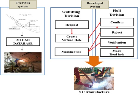
Figure 1 compares the processes before and after using the NC cutting system. In the past, holes were constructed in the field by workers using drawings, but the developed system can generate holes and perform NC processing with the coordinates of the holes only. According to the system flow, the outfitting design department first creates virtual holes with the hole information and coordinates and stores them in the database. The stored data can be modified and deleted as needed. The developed system ensures safe work and accurate construction. The main content of this paper is to propose an automatic generation system that can perform 3D modeling of holes using accurate hole design data and generate shell plate holes in the NC processing stage. This paper is organized as follows. After the Introduction section, Section 2 introduces the overall system structure, Section 3 describes the system configuration, Section 4 presents the system application results, and finally, Section 5 draws relevant conclusions.
2. System Structure
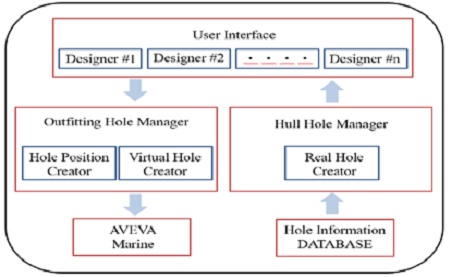
The overall structure of the developed system is shown in Figure 2. The left side of this figure consists of the “Outfitting Hole Manager,” which generates virtual holes with the hole shape information and coordinates and stores them in the database, and AVEVA Marine for managing the information on the hole shapes and shell plate to be constructed.
The right side of Figure 2 consists of the “Hull Hole Manager” for generating actual holes through the hole information and “Hole Information Database” for managing the hole coordinates and other hole information.
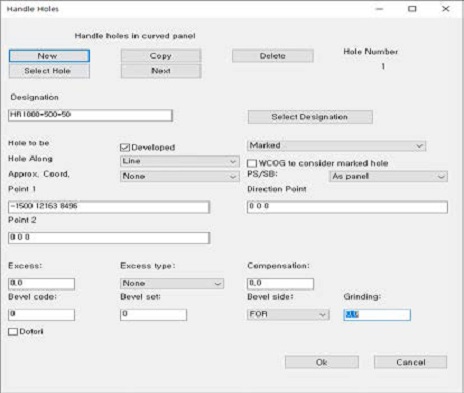
Figure 3 shows the input window for receiving the hole information of the shell plate in the hole drawing work as a tool of AVEVA Marine [5]. This input window is composed of several sections. Users can select the hole shape in “Designation,” select the reference axes (X,Y) of the holes in “Approx. Coord.,” choose whether to process the holes as “Marked” or “Burnt”, and enter the coordinate point of the hole in Point 1. “Marked” and “Burnt” indicate virtual and real holes, respectively. The reason for distinguishing virtual and real holes is to distinguish whether the hole can be finally processed in the NC workshop or whether it needs to be modified.
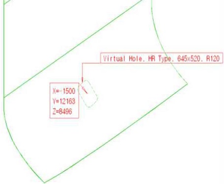
Figure 4 shows a virtual hole generated through the input window using the hole coordinates and other information found with the developed algorithm. The drawing worker verifies the hole position and information through 3D modeling and stores them in the database. The conventional method has a high possibility of construction error because the shell plate holes are processed manually. However, the NC hole cutting illustrated in Figure 4 can improve production efficiency and minimize construction errors.
3. System Configuration
3.1 System overview
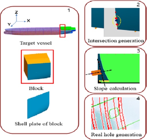
Figure 5 shows the total hole generation process using AVEVA Marine. A ship model is provided by AVEVA Marine in which there are many blocks, pipes, and shell plates. Among them, only the shell plate information of the block in which holes will be constructed is loaded. Then, the virtual holes are generated using the developed algorithm and stored in the database. The database contains virtual holes and their information; the hull department generates real holes using the data stored in the database and then performs NC processing. The algorithm consists of two parts: virtual hole generation using code and real hole generation.
3.2 System Algorithm
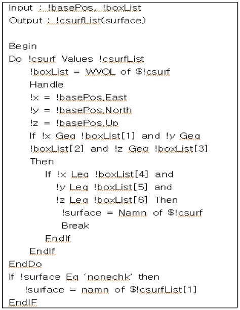
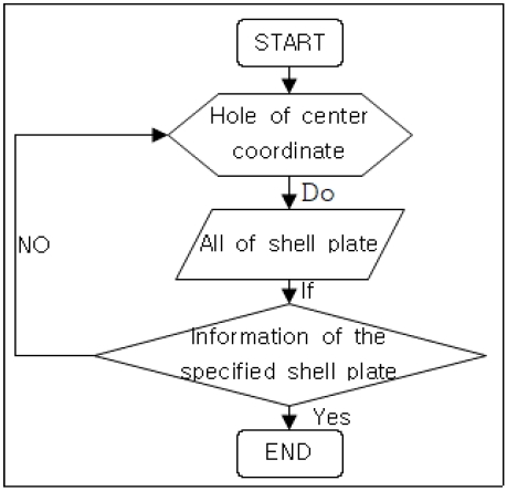
To generate holes that fit the shape of a curved shell plate, the coordinates including direction for the processed plane need to be calculated. An algorithm was developed to sequentially load the names of all blocks and shell plates stored in random variables, find the shell plate to which the center coordinates of the hole belong, and then store it in “!csurfList,” which was specified as a random variable (Figures 6 and 7) [6].
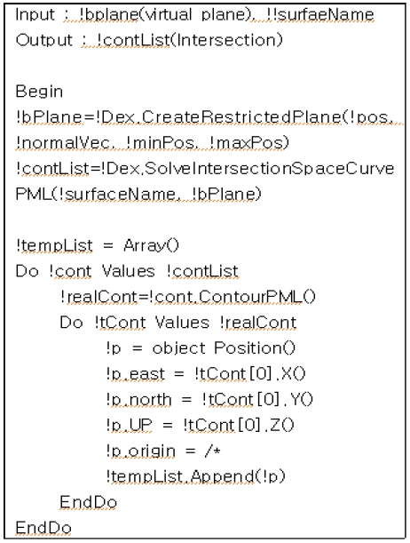
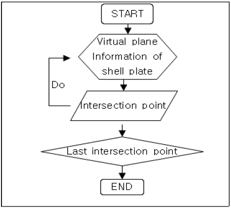
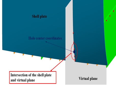
The variable !basePos represents the information of all shell plates; the variables !x, !y, and !z represent the x, y, and z values of the center coordinates, respectively. Furthermore, the variable !noneChk represents the random name of the shell plate in which the hole will be generated. Figures 8 and 9 show an algorithm for creating a virtual plane (gray) and an intersection (red dot) at the point where the shell plate and virtual plane intersect. The function “!bplane” for generating a virtual plane is a method of the library provided by AVEVA Marine. This method uses the location, normal vector, minimum location value, and maximum location value to generate a plane as large as the overlapping shell plate.
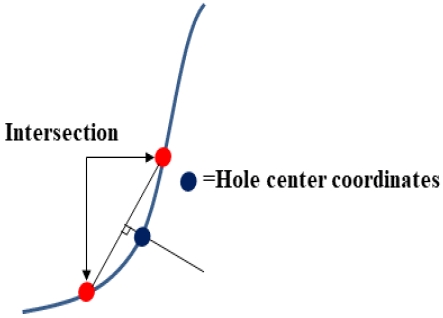
The function “!conList,” provided by AVEVA Marine, is composed of the name of the previously extracted shell plate and virtual plane. Many intersections are generated at the part where the shell plate contacts the virtual plane, and all the generated intersections are stored in the variable “!conList.” Furthermore, among all the stored intersections, two intersections to which the center coordinates of the hole belong are stored in the variable “!tempList.” Figure 10 shows the generation of an intersection between the shell plate and virtual plane at which the real hole will be generated through the above-mentioned two algorithms. The generated intersection is used to calculate the slope.
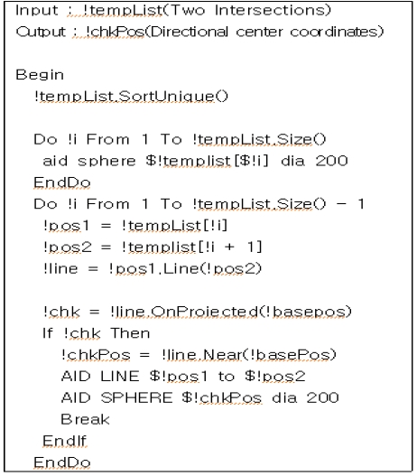
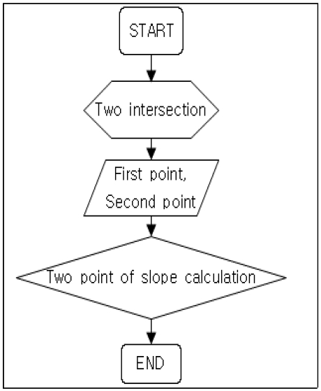
Figures 11 and 12 show the algorithm for calculating slope using the method for the two intersections stored in the variable “tempList” and applying the calculated slope to the center coordinates. Two intersections are used in the slope calculation method using two points because it is difficult to code accurate calculations of the slope of a curved surface. The variables “!pos1” and “!pos2” represent the first and second intersections, respectively. For the variable “!line,” the slope of a straight line is calculated using the “line.OnProjected” method by considering the first and second intersections as a straight line. The calculated slope value is applied to the center coordinates, which are the values of center coordinates with a direction. Figure 13 illustrates the “onprojected” method in the algorithm to facilitate understanding.
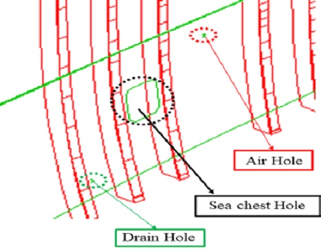
Figure 14 shows the sea chest, drain, and air holes. The sea chest hole was generated by inputting the center coordinates of a direction extracted using the above-mentioned algorithm and hole shape information in the hole generation input window. The drain and air holes were generated by inputting the coordinates marked on the drawing in the hole generation input window, omitting the algorithm process. For drain and air holes, the accurate hole shape is not important unlike the sea chest hole, because the hole size where the pipe interferes is not so large as to influence the ship structure and because the holes are used to discharge air and water. Therefore, the process of the above-mentioned algorithm may be bypassed, and the holes can be generated just by inputting the coordinates on the hole generation input window.
4. System Application Results
Previous works have proposed process automation systems related to outfitting-related members (pipe hole, plumbing hole, and cable hole) and inner holes but shell plate work was performed manually due to the nature of the curved shell plate. Manual cutting, in particular, requires high-place work depending on the cutting position, prior marking for the cutting position and shape, and additional grinding work if the cut shape is not good.
In this study, the outfitting and hull departments jointly proposed the shell plate automation hole generation process. The outfitting department stored the hole information and modeling of the virtual hole in a database. Based on the stored data, the hull department created the real hole and performed the NC process.
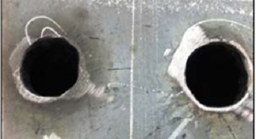
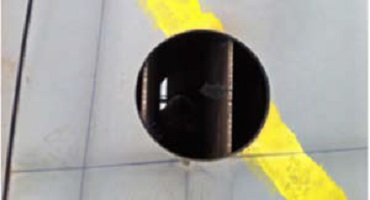
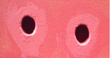
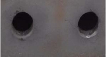
Table 1 shows a photograph before applying the shell plate hole processing system on the left and a photograph after applying the shell plate hole processing system on the right. The feasibility of this method has been verified by its application to a bulk ship built in a shipyard in 2018. For the cutting equipment, manual cutting with an oxygen welder was performed before applying the system; however, the NC automatic cutting system was used for the shell plate automatic hole generation system. The developed system can reduce casualties by preventing falling risks and improve the final quality of the cutting surface with minimal errors compared to conventional methods. Furthermore, the hole processing time was reduced to approximately 10 min to reduce the cutting man-hours compared to the existing manual cutting system (approximately 3 h).
5. Conclusion
In this study, the 3D CAD system AVEVA Marine was used instead of existing 2D design software. The objective of this study is to apply the developed system to the hull surface. As 3D information is essential for the hull surface, the 3D CAD system can improve the process throughout the process covering 3D modeling, design, and construction. This software is especially popular in the outfitting design and construction fields.
The developed shell plate hole processing system is an automation system that can model holes using the hull surface and hole information and be applied to shell plates as well as the inner plates of ships. According to the “2018 Shipbuilding Industry Disaster Cases” [7] published by the Korea Occupational Safety and Health Agency, many falling accidents occur during the shell plate work. Through the developed system, shell plate hole construction can be done automatically using NC cutting equipment instead of field construction. Consequently, safety problems such as production accidents that may occur in the field, hole accidents at high positions such as workers falling, and secondary accidents due to falling work tools can be prevented. Furthermore, its implementation is expected to improve the quality of ships by reducing hole cutting man-hours and improving the efficiency of production and design processes. However, it was difficult to adjust the intervals of intersections in this study. In the future, we will research more accurate slope calculations and their application to holes by making it possible to adjust the distance between intersections.
As shown in Figure 14, the results of applying the developed shell plate hole processing system showed that for some holes that are large or located at the edge of a member, there is a possibility of deformation of the shape or position of the hole due to plate forming. Hole shape changes due to plate forming can be prevented through “bridge work,” which is often used in shipyards, and problems can be minimized by standardizing bridge construction methods.
Acknowledgments
This work was performed as part of the regional-specialized technology development and expansion of the open laboratory project of Busan Innovation Institute of Industry, Science, and Technology Planning.
Author Contributions
Conceptualization, Y. J. Yang; methodology, C. S. Kim; Software, C. S. Kim; Investigation, All Authors; Resources, All Authors; Writing-Original Draft Preparation, C. S. Kim; Writing-Review & Editing, Y. J. Yang; Supervision, Y. J. Yang; Project Administration, Y. J. Yang.
References
- S. H. Kim, J. T. Kim, H. C. Kim, I. S. Yu, G. S. Jo, H. S. Jo, and Y. T. Choi, “The automated application method of ship hull outfitting hole structure modeling,” Korea, KR20120019537A, Mar. 7, 2010 (in Korean).
-
W. S. Ruy, Y. S. Yu, and D. E. Ko, “A Study on the Hole-Plan system combined with 3D CAD,” Journal of the Korea Academia-Industrial cooperation Society, vol. 13, no. 1, pp. 1-7, 2012 (in Korean).
[https://doi.org/10.5762/KAIS.2012.13.1.1]

-
W. S. Ruy, D. E. Ko, and Y. S. Yang, “The implementation of the integrated design process in the hole-plan system,” International Journal of Naval Architecture and Ocean Engineering, vol. 4. no. 4, pp. 353-361, 2012.
[https://doi.org/10.3744/JNAOE.2012.4.4.353]

- H. W. Suh and S. G. Lee, “Integrated CAD system for ship and offshore projects,” International Journal of CAD/CAM, vol. 6, no. 1, pp. 41-48, 2006.
- AVEVA, AVEVA Marine(12.1) Hull Detailed Design – Planar Hull Modelling
- AVEVA, AVEVA Marine(12.1) Programmable Macro Language
- A book of Cases in Serious Disasters in Shipbuilding Industry, http://ww2.mynewsletter.co.kr/kcplaa/202005-2/1.pdf, , Korea Occupational Safety & Health Agency, 2018 (in Korean).

