RFID- and MEMS-based onboard crew location recognition system for incident response
Copyright ⓒ The Korean Society of Marine Engineering
This is an Open Access article distributed under the terms of the Creative Commons Attribution Non-Commercial License (http://creativecommons.org/licenses/by-nc/3.0), which permits unrestricted non-commercial use, distribution, and reproduction in any medium, provided the original work is properly cited.
Abstract
In the event of an incident on a ship, the crew should respond in accordance with the relevant regulations and guidelines. The incident response team is formed to respond to fire or flooding situations and approach the damaged area to perform the incident response operations. From the ship captain’s viewpoint, location recognition of the incident response team is important to decide the incident response action, such as entering time to the damaged zone, evacuation order, and route control. Thus, as ships become larger and their internal structure becomes more complex, the commands of incident response using portable radio become limited. Therefore, a crew location recognition system for onboard incident response combining radio-frequency identification (RFID) and microelectromechanical systems (MEMS) was considered for application to the existing computerized incident response system or damage control system (DCS) adopted by large passenger ships and naval vessels.
Keywords:
RFID, MEMS, Crew location recognition, Incident response, Fire, Flooding1. Introduction
It is well known that the impact of an incident in a ship spreads very quickly when the initial response fails, and even a competent crew member has difficulties responding adequately in emergency situations such as fire and flooding. In the case of a fire incident, if the firefighting action with personal fire extinguishing equipment fails at the time when the incident is recognized, a firefighting team immediately starts operation, entering the incident site and performing the usual fire extinguishing operations [1]. Blocking of air ducts and checking of heat transfer at the border of the entry area, along with cooling actions, are generally carried out. The toxic smoke and heat generated during a fire are major factors that hinder the entry and operation of the firefighting team. Decisions such as access route to the fire site and timing of the approach for the firefighting team, closure of the area according with the fire extinguishing
Conditions, and CO2 fire extinguishing using the fixed fire main pipe are made by the team leader [2]. Currently, the firefighting team and the captain of the ship usually use portable radios to send and receive information about the situation, but the information delivered by voice in this way is limited, especially for identifying the location of the firefighting team in real time and instructing the appropriate actions [3]. In the case of flooding incidents, it is also necessary to verify the location of the incident response team, determine the entry and evacuation points of the incident site, and use the information for setting the entry and evacuation routes. For this reason, incident response systems (damage control systems (DCS) or incident response support systems (IRSS)), the use of which is currently increasing especially for large passenger ships and naval vessels, tend to involve a location recognition service of the incident response team or those under the category of vulnerable users in the ship (for privacy protection, this is applicable only to those who have expressed their consent) [4]. In this study, we considered the movement characteristics of the incident response team, and the existing location recognition technology, which performs location recognition with the signal strength of ZigBee [5] has examined. By combining the radio-frequency identification (RFID) technology, which is advantageous in terms of battery life and cost, and microelectromechanical systems (MEMS) to enable the location recognition of people passing through the RFID reader, further improved system suggested. The usability of the proposed system was examined through onboard tests.
2. Characteristics of Location Recognition of Crew Onboard
2.1 Principle of crew location recognition
Most ships are made of steel with watertight doors and hatches and are composed of multiple layers of decks. This makes it difficult for radio signals to be transmitted beyond a single deck or zone [6][7].
For this reason, crew location recognition based on a wireless terminal inside the ship is generally performed by installing a reader in a zone unit inside a single deck.
Table 1 presents a specification of RFID tags and readers considered for location recognition of the incident response team on a single deck zonal basis. A location recognition system based on a wireless communication network installed inside a ship can use terminals such as RFID or ZigBee. However, in this study, the RFID tag was considered a priority owing to its relative advantage in terms of power consumption [9]. Among the RFIDs of various frequency bands, the use of the RFID in the 900 MHz band, which has low cost and relatively long recognition distance and is also utilized in automatic toll collection and logistics management, was first considered. This is because the distance to the ship's watertight zone (main vertical zone (MVZ)) is generally over 15 m, and the RFID in this frequency band can rapidly verify the location of incident response team through the door of the watertight zone or the hatch between decks without missing reliability. The location recognition for each zone focuses on recognizing the crew movement in the watertight zone and deck units using RFID tags. The data identified with the RFID tag is collected through Ethernet and displayed on the tech plan for incident response. As for the display of the location recognition, the method of displaying the deck and zones where the incident response team is located based on the MAC address of the RFID reader was adopted.
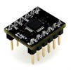
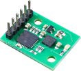
For the location recognition of the incident response team, which is primarily identified in the RFID readers installed in the watertight zone and deck units, we considered a method using a MEMS sensor. This method takes into account the situation where the incident response team moves at the same time along the shortest path in the course of entering or evacuating the incident site, and it determines the overall location between RFID readers by estimating the movement orientation and displacement of the incident response team based on the 3-axis acceleration value of the MEMS sensor [10]. However, this type of MEMS sensor cannot be used for location recognition of a vulnerable user inside a passenger ship who shows irregular and repetitive movement characteristics in the zone. For processing of the location identification data in the zone, a Kalman filter algorithm is used to process the roll and pitch values of the MEMS sensor. Table 2 lists the specifications of the MEMS sensor considered for estimating the location of an incident response team moving between RFID readers in the unit zone [11]. In this study, a MEMS sensor in the form of a component that can be easily embedded in the radio of a crew was first considered owing to the following reasons: 1) The RFID tag and MEMS sensor used for the location recognition of the incident response team must be carried by the moving crew. 2) It is necessary that it be in charged state in normal days and can be used for long enough time when it is required. 3) It is necessary for the system to be small in size. Table 2 includes the specifications of the MEMS sensor that can be considered. In this study, the application of the commercial MEMS components shown on the right was first considered.
2.3 Unit testing of RFID and MEMS sensors
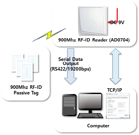
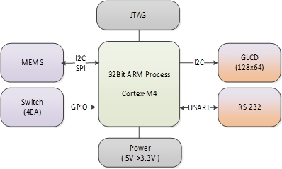
To effectively utilize the location information of the incident response team during the incident response process, the information of the RFID tag and the MEMS sensor must be processed together to display the location information in real time. Figure 1 shows the Ethernet-based data reception rate of a 900 MHz RFID tag with a maximum recognition distance of 15 m, typically of 1 to 5 m. Using an onboard network, an RFID reader is installed, and the location data is collected by the RFID tag. It consists of a new module that includes a component type MEMS sensor and performs communication in accordance with the RS-232 standard while utilizing and converting a 5 V power supply to 3.3 V. More specifically, the 3-axis acceleration gyro is measured in the MEMS block, and the display item conversion is performed in the GLCD in the switch block. The JTAG block includes a download debugger, and the Cortex-M4 block receives data from the MEMS and performs gyro, distance, and algorithm calculations. The GLCD block indicates the travel distance and gyro. The RS-232 block performs wireless communication of serial data.
Figure 2 depicts a block diagram of location identification based on a MEMS sensor.
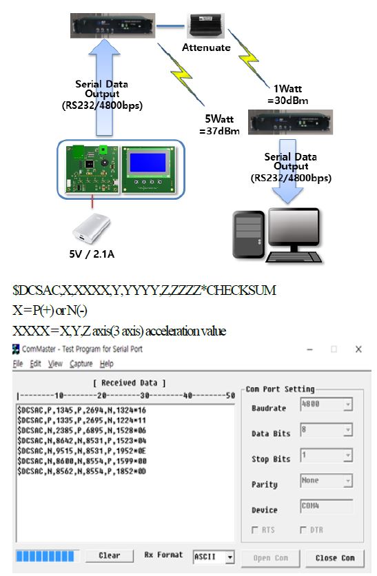
Figure 3 (up) describes the block diagram of Figure 2 from the perspective of collection and analysis of location recognition data. The location recognition result using the MEMS sensor is displayed in ZZZZ * CHECKSUM format, as shown in Figure 3 (down), where the first “X” is categorized into “P” for acceleration in the plus-direction and “N” for acceleration in the minus-direction, and the next “XXXX,” “YYYY,” and “ZZZZ,” are the numerical display of the acceleration values.
3. Configuration of Test Module
3.1 Configuration of wireless terminal and reader and unit test
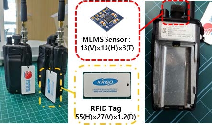
RFID tags and MEMS sensors must be integrated into a single terminal to continuously determine the location of the incident response team moving to the incident site in the deck and zone units. Therefore, the method of embedding the RFID tags and MEMS into the radio is a priority in consideration of portability and usability. The portable radio was assumed to be carried by the crew members in charge of the safety of each zone or the incident response team leader. The MEMS sensor was constructed in such a way that the component type sensor specified in Table 2 was fabricated with a separate signal processing part, as depicted in Figure 2, and this was embedded in the UHF radio used in the ship. Figure 4 shows the radio with the RFID tag and MEMS sensor embedded for location recognition of the incident response team.
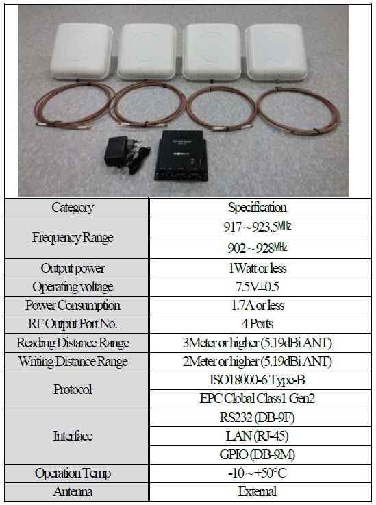
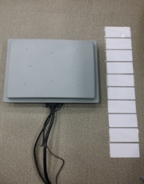
To verify whether the fabricated wireless terminal can send information on the incident response team's location recognition at a level that can be actually used, a test was first conducted inland. First, the RFID reader was placed and it was tested whether the RFID tag of the moving crew was recognized and how reliable the location information provided by the MEMS sensor was. A four-channel reader for multiple RFID tags was configured as shown in Figure 5 to prevent the data loss that would occur with a single-channel reader configuration.
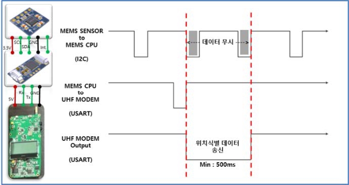
As a result of the test, the RFID tag performed without missing recognition during both walking and running, but in the case of location information using MEMS, an error in the gyro side occurred, up to 60°, showing a large error. With the judgment that the radio's 444.1 MHz frequency may have affected the MEMS sensor, after using a trial and error method, ground (GND) was added to the MEMS module installed in the radio. In addition, the distance between the MEMS module and the radio antenna was adjusted to 40 mm or more and the RF transmission output of the MEMS module was slightly adjusted from 1 to 0.7 W. As for the data transmission of the MEMS sensor, at the same time that the MEMS CPU received the data request from the UHF modem, the requested data was transmitted using the USART method via a UHF modem. At this time, to prevent the data loss due to the RF output noise occurring during the continuous process and transmission of data, the data generated for 500 ms during wireless transmission of the radio was discarded. The data was processed when the transmission was completed, so that the data loss could be reduced.
Figure 6 shows the result of configuring the data processing algorithm to prevent the loss of MEMS sensor data and the decrease in reliability due to wireless signals, which helped secure location recognition information of the incident response teams moving in a linear direction.
3.3 Inland test on the location recognition function
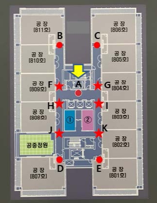
The location identification module for each zone used four-channel RFID readers. In 20 tests with two or more overlapping personnel carrying the radio and passing by, apart from one case in which the tag was completely obscured by others, all were recognized, which confirmed a recognition rate over 95%. As for the location recognition of the crew passing through the area between the RFID readers, given that the distance of crew movement was measured by the size of SVM, the test was conducted with a focus on the location recognition capability based on MEMS. Figure 7 shows the inland test site configured to test the movement and measured gyro data using UHF communication based on the MEMS module with the gyro error adjusted.
As a result of the test using a portable radio equipped with the embedded RFID tag and MEMS sensor at a test site configured in inland, in the case of a pattern moving from A to B, there was an F point in which the gyro changed and the received data at the F point was in the range of 315° ± 15°. In the case of a pattern moving from A to C, there was a G point in which the gyro changed and the received data at the G point was in the range of 45° ± 15°. In the case of a pattern moving from A to D, there was an H point in which the gyro changed and the received data at the H point was in the range of 225° ± 15°. In the case of a pattern moving from A to E, there was a K point in which the gyro changed and the received data at the K point was in the range of 135° ± 15°. Finally, in the case of a pattern moving from A to A, there were H, J, K, and I points in which the gyro changed and the received data at these points were in the range of 225° ± 15° for H, 135° ± 15° for J, 45° ± 15° for K, and 315° ± 15° for I.
In location identification within a zone, there is a point where the gyro changes when the actual moving direction changes, and if these points do not appear, the data processing may indicate an erroneous false path for the gyro. Location tracking onboard is calculated with reference to gyro data for movements based on a structure that is fixed, and thus, the identification of the point where the gyro changes plays an important role in the location identification within the zone. That is, when a crew with a radio moves repeatedly between RFID readers, it should be considered that the accuracy of location estimation using a MEMS sensor may decrease.
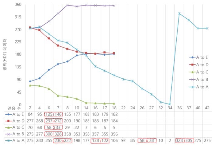
Figure 8 shows the crew heading (HDT) data for a number of steps as a test result of the location identification module in the zone of I point of the [A to E], H point of the [A to D], G point of the [A to C], and F point of the [A to B]. It was confirmed that there is data in the range wherein the heading (HDT) changes at steps 6 and 7. In the case of the [A to A], the same type of heading (HDT) as a circular motion and that there was data in the range wherein the heading (HDT) changes in steps 7 and 8 for the H point, in steps 16 and 17 for the J point, in steps 26 and 27 for the K point, and in steps 36 and 37 for the I point.
3.4 Onboard interlink operation test of the incident response system
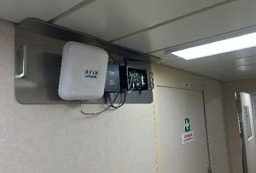
In practice, the RFID reader and UHF module were fabricated as shown in Figure 9 and attached to a wall near a door of the ship using a magnet. The location of the moving crew on the screen of deck plans tested by using the onboard Ethernet.
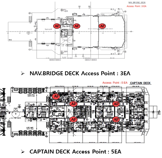
The test of crew location recognition was conducted on a ship with the layout presented in Figure 10. Three access points for location recognition test were installed on the bridge deck and five on the captain deck. The location recognition function was investigated by determining with how much error the crew's movement through each RFID access point could be detected between each RFID access point.
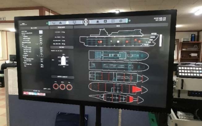
As shown in Figure 11, it is verified that the location of the crew moving in the test zone is detected from the time the RFID tag is first recognized by a reader to the point of recognition by the next reader. It is also verified that the data sent from the MEMS sensor can be displayed on the console screen of the incident response system. The location of the incident response team displayed on the deck plan of the user interface screen from the time when the incident is confirmed to the end of it.
Figure 12 shows the location of the moving crew on the user interface of the incident response system using the Ethernet network installed onboard.
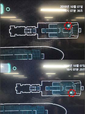
Onboard interlink operation test results of the crew location recognition system and user interface of the onboard incident response system
As for the onboard test, it was impossible to conduct the necessary repeated tests to confirm a statistically significant error rate due to the difficulty of sharing the ship's schedule and communication network. However, it was possible to obtain similar results to the inland test upon conducting the tests several times. In the Ethernet environment installed onboard, it was confirmed that the RFID tag information recognized by the reader near the door and the location of the incident response team on the move were displayed on the user interface of the test incident response system. However, there could be location recognition errors due to the accumulation of motions in a large space, not in a passage moving in one direction. Therefore, additional and repeated tests are thought to be needed to investigate the tendency of the errors by determining the statistically significant error characteristics and correcting them accordingly.
4. Conclusion
In this paper, the results of our research on a technology to identify the location of the crew on board a ship and display the information on the user interface of the incident response system in real time were presented. We expect that this technology can be utilized in connection with computerized incident response systems, the use of which is increasing in large passenger ships and naval vessels.
To effectively respond to incident situations in ships divided into many zones and having complex internal structures, a method combining MEMS sensors with RFID tags, which are a conventional location recognition tool, was proposed for location recognition of the incident response team. As the incident response team passed through the RFID readers installed at regular intervals, the results continuously confirmed the technical feasibility of real-time location recognition. To this end, in this study, a portable terminal was constructed in the form of an embedded MEMS sensor in the radio used in a ship with an RFID tag also attached. In addition, by connecting the RFID reader and RF receiver to the existing Ethernet network installed in the ship, it was possible to recognize the crew location and display it on the user interface of the incident response system. Thus, this crew location recognition technology can be used without additional cost or the burden of retrofitting the ship. However, there are still limitations in this study because the test results did not manage to process the gyro angle of the ship, which changes during sailing, and the relative value of the movement gyro of the crew. There was a statistically significant error rate on the movement distance and the improvement measures are not presented. Therefore, improvements and technical alternatives are required through further research.
In addition, in case the ship's communication network is disabled due to a fire or similar incidents, it is necessary to consider the implementation of an uninterruptible power supply system that can be maintained for a certain period of time or the configuration of an ad hoc network. Apart from the function of location recognition of the incident response team, the location recognition technology proposed in this study is expected to provide other services, such as location recognition of vulnerable users that need protection and services reflecting the personal preferences of the crew or passengers. This will be achieved through additional complementary studies.
Acknowledgments
This research was conducted as part of the “Development of incident response system technology that enables real-time response to ship damage and fire” project supported by the Ministry of Trade, Industry, and Energy (Project No. 10052660, PNS3420) and the in-house research project (PKS1040) of the Korean Research Institute of Ships & Ocean Engineering. We acknowledge their support to the research fund.
Author Contributions
Conceptualization, S. J. Kim and H. J. Kang; methodology, S. J. Kim, J. G. Kang and B. K. Choi; Software, S. J. Kim; Formal Analysis, S. J. Kim; Investigation, S. J. Kim and J. G. Kang; Resources, S. J. Kim, J. G. Kang, and H. J. Kang; Data curation S. J. Kim and H. J. Kang; Writing-Original Draft Preparation, H. J. Kang and S. J. Kim; Writing-Review & Editing, H. J. Kang and D. K. Lee; Visualization, S. J. Kim and H. J. Kang; Supervision, H. J. Kang, B. K. Choi and D. K. Lee; Project Administration, D. K. Lee; Funding Acquisition, D. K. Lee and H. J. Kang.
References
- Safety4sea, Procedures: A Step-by-Step Guide for Safe Abandon-Ship Drills (2018), https://safety4sea.com/cm-procedures-a-step-by-step-guide-for-safe-abandon-ship-drills, , Accessed April 24, 2020.
-
H. J. Kang, J. Choi, D. K. Lee, and B. J. Park, “A framework for using computational fire simiulations in the early phases of ship design,” Ocean Engineering, vol. 129, pp.335-342, 2017.
[https://doi.org/10.1016/j.oceaneng.2016.11.018]

- Maritime DC & PPE Information Center, http://www.dcfpnavymil.org, , Accessed April 23th, 2020.
- L3 MAPPS, https://www2.l3t.com/mapps, /, Accessed April 23th, 2020.
-
H. J. Kang, D. K. Lee, J. G. Shin, and B. J. Park, “Location tracking of moving Crew for effective damage control in an emergency,” Defence Science Journal, vol. 61, no. 1, pp. 57-61, 2011.
[https://doi.org/10.14429/dsj.61.503]

-
H. Wang, H. Lenz, A. Szabo, J. Bamberger, and U. D. Hanebeck, “WLAN-based pedestrian tracking using particle filters and low-cost MEMS sensors,” 2007 4th workshop on positioning, navigation and communication, IEEE, pp. 1-67, 2007.
[https://doi.org/10.1109/WPNC.2007.353604]

-
B. G. Paik, S. R. Cho, B. J. Park, D. K. Lee, B. D. Bae, and J. H. Yun, “Characteristics of wireless sensor network for full-scale ship application,” Journal of Marine Science and Technology, vol. 14, no. 1, pp. 115-126, 2009.
[https://doi.org/10.1007/s00773-008-0038-x]

-
K. Koski, L. Sydänheimo, Y. Rahmat-Samii, and L. Ukkonen, “Fundamental characteristics of electro-textiles in wearable UHF RFID patch antennas for body-centric sensing systems,” IEEE Transactions on Antennas and Propagation, vol. 62, no. 12, pp. 6454-6462, 2014.
[https://doi.org/10.1109/TAP.2014.2364071]

- D. M. Shin, S. H. Choi, and G. S. Lee, “RFID Applications from 2005 to 2010,” Journal of Ocean Engineering and Technology, vol. 24, pp.86-93, 2010.
-
P. Ragam and D. S. Nimaje, “Selection and evolution of MEMS accelerometer sensor for measurement of blast-induced peak particle velocity,” IEEE Sensors Letters, vol. 2, no. 4, pp. 1-4, 2018.
[https://doi.org/10.1109/LSENS.2018.2872624]

-
W. Li and J. Wang, “Effective adaptive Kalman filter for MEMS-IMU/magnetometers integrated attitude and heading reference systems,” The Journal of Navigation, vol. 66, no. 1, pp. 99-113, 2013.
[https://doi.org/10.1017/S0373463312000331]


