Study on power line communication for high voltage cables of electric vehicles
Copyright ⓒ The Korean Society of Marine Engineering
This is an Open Access article distributed under the terms of the Creative Commons Attribution Non-Commercial License (http://creativecommons.org/licenses/by-nc/3.0), which permits unrestricted non-commercial use, distribution, and reproduction in any medium, provided the original work is properly cited.
Abstract
Recently, electric vehicles have been highlighted as a major alternative to internal combustion engine cars. Electric vehicles require large batteries to provide sufficient mileage and power; this requirement leads to an increase in weight of the vehicle. However, increase in weight of the vehicle decreases its efficiency; therefore, an alternative to reduce the weight is necessary. Power line communication (PLC) does not require dedicated communication lines as it shares existing wires, which makes it an efficient way to avoid increasing the amount of cabling even when new communication equipment is added. In this study, channel analysis and communication bandwidth measurements were carried out using the high voltage power line of electric vehicles. Consequently, both real-time image transmission using an IP-cam and object recognition using Raspberry Pi were successfully performed.
Keywords:
Power line communication, Electrical vehicle, Ferrite coupler, Deep learning1. Introduction
An electric car is a vehicle that uses electricity as its fuel and an electric motor as its power engine. For a long time, internal combustion engine vehicles have mainly been used. Since the mid-2000s, electric cars have become representative of the next generation of eco-friendly cars. In particular, global electric vehicle supply totaled 3.1 million units in 2017, which indicates a high interest in them. Electric vehicles require high energy density, lightweight, and high capacity batteries that can offer an adequate range on a single charge. Power lines and cables in electric vehicles account for 20 percent of the vehicle's weight, and most electric vehicles have more than 200 connectors [1]. Installing additional power lines for various functions increases the weight of the vehicle, thereby reducing the performance and efficiency of it. Hence, the increased amount of power lines leads to weight problems. It is, therefore, very important to develop communication technologies that can reduce the amount of cable used. Among several communication technologies, power line communication (PLC) appears to be a very good solution. The application of PLC to electric vehicles takes advantage of existing networks to enable high-speed data communication, resulting in significant gains in terms of cost and weight reduction. Previous studies have mainly applied PLC to internal-combustion engine vehicles, but it is suitable for use in both internal-combustion engine vehicles and electric vehicles [2]-[3].
In this paper, channel analysis and communication bandwidth measurements were conducted using inductive couplers on high voltage power lines in electric vehicles. Real-time image transmission experiments using an IP-cam demonstrate that sufficient bandwidth is available for data communication. In addition, we applied a deep learning model to recognize objects in front of the vehicle and convert the detected object information into text, which was subsequently transferred to a monitoring PC. The possibility to use inductive PLC with high voltage lines of electric vehicles was fully confirmed.
2. Relevant technologies
2.1 Power line communication
PLC is a communication method that transmits high-frequency signals using the low power line frequency (60 Hz) as a carrier. The transmitted signal is extracted only at the desired frequency from the power line using an inductive coupler and is then demodulated in the power line modem. Since inductive PLC is applied to the existing power lines, installation costs are lower than for wireless communication systems and system maintenance costs can be reduced.
In this study, inductive PLC is applied to the high voltage power line of an electric vehicle. Since PLC uses existing power lines or wires inside electric vehicles, it is a good way to reduce the weight of the vehicles because there is no need to add a dedicated communication line even if new communication functions are added. A research group at Toyota has attempted to analyze channel characteristics and measure the impedance of high-voltage power lines in electric vehicles, and they reported that PLC could be used for electric vehicle communication [4].
2.2 Soft magnetic core-type coupler
Generally, ferrite is used in the coupling unit for inductive PLC [5]-[6]. Magnetic materials are divided into ferromagnetic, paramagnetic, semi-magnetic, and ferrimagnetic. Ferromagnetic material has a strong magnetized property where magnetic dipoles are arranged in the same direction as external magnetic fields. Paramagnetic material is randomly arranged if the magnetic dipoles do not have an external magnetic field, but if there is one, then they are arranged in the direction of the magnetic field. Semi-magnetic materials, however, have magnetic poles that do not magnetize without an external magnetic field, but if an external magnetic field is present, then magnetic dipoles are arranged in the opposite direction to it. The ferrite used in this experiment is a ferrimagnetic material, which is similar to a ferromagnetic material, but has the advantage of low loss due to induced currents as it exhibits a large electrical resistance [7]. Inductive type ferrite core couplers enable high-speed data transmission based on PLC [8]-[9]. The couplers used in this experiment are shown in Figure 1.
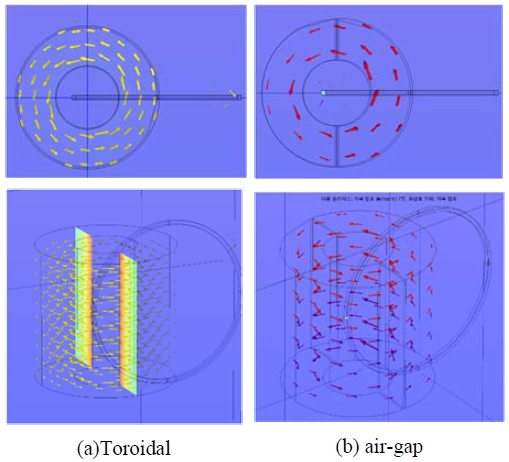
The magnetic flux of the coupler induced by the primary current was analyzed using the Comsol program [10] and is shown in Figure 2. Magnetic flux density distributions of the toroid coupler and the air-gap coupler were compared and their magnetic flux energies were calculated. Measurement results for the magnetic flux energy were 1.823 ✕ 10-8J for the toroidal coupler and 3.232 ✕ 10-10J for the cut-core coupler, respectively. The magnetic flux in the toroidal coupler is trapped inside the core; however, in the cut type coupler, part of the magnetic flux leaks out through the air gap. Therefore, a high magnetic saturation current allows the PLC system to operate even in environments where the line current fluctuates significantly. In addition, the air gap of the coupler has the advantage that the PLC system can be mounted on the power line without damaging it. The primary winding of the coupler consists of one turn to minimize the insertion loss.
2.3 Tensor flow object detection
Recently, a number of artificial intelligence-based systems have been applied to electric vehicles. Among these, deep learning-based systems, in particular, provide various functions and convenience. Deep learning is the most promising technology for developing artificial intelligence and many application models are being announced. Deep learning is a part of machine learning, but it includes computations and learning processes that are more complex than machine learning. Vehicles equipped with deep learning systems are used for example, in applications such as pedestrian detection and detecting traffic signals and signs for autonomous driving. There are numerous libraries and frameworks for deep learning algorithms. In this study, object detection was carried out using python-based Tensorflow. An object detection model was utilized in the in-vehicle PLC performance test. A Raspberry Pi with a deep-learning model was added to the PLC system to detect objects in front of the vehicle and transmit the results to the monitoring PC.
3. Experiments and results
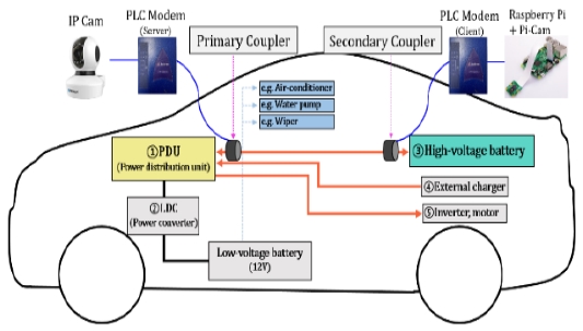
The experiment was carried out using an electric vehicle owned by Ulsan Technopark Green Car Center. The internal configuration and experimental setup were as shown in Figure 3. The primary and secondary couplers were installed at particular locations within the vehicle, and channel analysis and bandwidth measurements were conducted. The primary coupler was connected to the server PLC modem and the secondary coupler attached to the client PLC modem. The client was also connected to the monitoring PC to measure channel bandwidth using the Jperf program. The modems used are devices that enable internet access and home networks using a home or office power-plug, without the need for a dedicated line. They are designed to operate between 2 MHz and 30 MHz and have a maximum bandwidth of 200 Mbps.
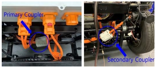
The experiment was conducted under two conditions, these being the engine turned on, and the engine turned off. In order to check whether data transmission through high voltage line PLC is possible, real-time image data transmission using an IP-cam, and an object detection test using Raspberry Pi were performed. First, the channel characteristics between the high voltage battery and the external charger were measured with a network analyzer (ZVH4, Rohde & Schwarz). The primary coupler connected to the high voltage battery and the secondary coupler attached to the external charger were as shown in Figure 4.
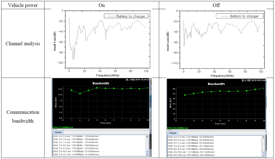
The spectral responses are shown in Figure 5. The channel loss variation with engine off was about -20 dB, but when the engine was on, the peak-to-peak insertion loss was about -40 dB. With the same coupler position, the channel bandwidth was about 12.6 Mbps when the engine was on and about 56 Mbps when the engine was off. In conclusion, it is shown that turning on the engine increases the noise on the high-voltage cable and significantly reduces the channel bandwidth.
Experimental results measured at different locations on the high voltage cable are summarized in Table 1. The same experiment was performed at four different points, but in all cases, the insertion loss was low with the engine off and the bandwidth was reduced when the engine was turned on. Even though the bandwidth was reduced while the engine was on, there was still enough bandwidth for Mbps communication services.
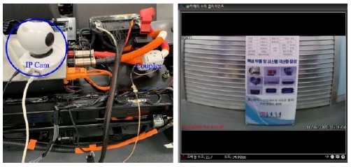
Real-time image transmission was conducted to check if data communication was possible. Based on the results shown in Table 1, the primary and secondary couplers were located at the high voltage batteries and the power distribution units, respectively, and an additional IP cam was installed at the primary coupler. The picture taken with the IP cam was sent to the secondary coupler via the high voltage power cable. As shown in Figure 6, the video recorded by the IP cam connected to the primary coupler was transferred to the secondary PLC system, and the image was played back to the monitoring PC.
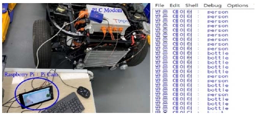
Finally, we demonstrated object detection using Raspberry Pi with a deep learning model. When the Pi cam captured object images in front of the vehicle, the Raspberry Pi recognized the object and sent the name of the object to the monitoring PC. As shown in Figure 7, the object names were displayed on the monitoring screen.
4. Conclusion
In this paper, the application of PLC using the high voltage cables of electric vehicles was studied. Channel analysis showed that when the engine was on, there was a lower insertion loss than when the engine was off. Based on the channel loss, communication bandwidth measurements were carried out for various locations in the EV. The bandwidth was lower when the engine was on than when the engine was off because of noise on the high voltage cable. However, even when the engine was turned on, there was enough Mbps bandwidth for video services. Based on these results, real-time image data transmission was successfully demonstrated. In addition, the Tensor Flow object detection test was successfully implemented in the EV high voltage cable PLC system. The results of this research will contribute to the lightening of the vehicles and the simplification of wiring.
Acknowledgments
This work was supported by the National Research Foundation of Korea (NRF) funded by the Ministry of Science and ICT (2017R1A2B4010993)
Author Contributions
Conceptualization, K. Sohn; Methodology, K. Sohn; Software, J. Jeong; Validation, J. Jeong and K. Sohn; Formal Analysis, J. Jeong and K. Sohn; Investigation, J. Jeong and K. Sohn; Resources, J. Jeong and K. Sohn; Data Curation, J. Jeong; Writing——Original Draft Preparation, J. Jeong; Writing——Review & Editing, K. Sohn; Visualization, J. Jeong; Supervision, K. Sohn; Project Administration, K. Sohn; Funding Acquisition, K. Sohn.
References
-
M. Lienard, M. O. Carrion, V. Degardin, and P. Degauque, “Modeling and analysis of in-vehicle power line communication channels,” IEEE, vol. 57, no. 2, 2008.
[https://doi.org/10.1109/TVT.2007.906372]

-
A. Pittolo, M. D. Piante, F. Versolatto, and A. M. Tonello, “In-vehicle power line communication: Differences and similarities among the in-car and the in-ship scenarios,” IEEE, vol. 11, no. 2, 2016.
[https://doi.org/10.1109/MVT.2015.2480098]

-
M. Takanashi, A. Takahashi, H. Tanaka, H. Hayashi, T. Harada, and Y. Hattori, “Channel measurement and modeling of high-voltage power line communication in a hybrid vehicle,” IEEE, pp. 52-57, 2014.
[https://doi.org/10.1109/ISPLC.2014.6812324]

-
M. Takanashi, T. Harada, A. Takahashi, H. Tanaka, h. Hayashi, and Y. Hattori, “High-voltage power line communication system for hybrid vehicle,” IEEE, pp. 222-227, 2015.
[https://doi.org/10.1109/ISPLC.2015.7147618]

-
J. H. Jeong, S. H. Yang, H. S. Kim and K. R. Sohn, “Soft magnetic-core coupler suitable for low-frequency band power-line communication,” Journal of the Korean Society of Marine Engineering, vol. 42, no. 10, 2018.
[https://doi.org/10.5916/jkosme.2018.42.10.823]

-
S. H. Yang, J. H. Jeong, H. S. Kim, and K.R Sohn, “Implementation of soft magnetic core type couple for broadband power line communication,” The Journal of Korean Institute of Communications and Information Science, vol. 44, no. 4, 2019.
[https://doi.org/10.7840/kics.2019.44.4.693]

- J. H. Jeong, S. H. Yang, W. J. Joo, H. S. Kim, and K. R. Sohn, “A Study on the low frequency inductive powerline communication system,” The Korean Institute of Electrical Engineers, pp. 22-23, 2018.
-
J. H. Jeong, S. H. Yang, H. S. Kim, and K. R. Sohn, “Power line communication characteristics of inductive cut-core coupling unit robust to current fluctuation,” The Journal of Korean Institute of Communication and Information Sciences, vol. 43, no. 9, 2018.
[https://doi.org/10.7840/kics.2018.43.9.1469]

- S. H. Yang, J. H. Jeong, W. J. Joo, H. S. Kim, and K. R. Sohn, “A study on the broadband powerline communication using nanocrystalline core,” The Korean Institute of Electrical Engineers, pp. 20-21, 2018.
- C. H. Kim, “COMSOL multiphysics 3.3,” The Korean Society of Mechanical Engineers, no. 46, pp. 22-23, 2006.


