Analytical evaluation of explosion-proof safety based on the international standard for Ex ‘d’ type LED working-lights
Copyright ⓒ The Korean Society of Marine Engineering
This is an Open Access article distributed under the terms of the Creative Commons Attribution Non-Commercial License (http://creativecommons.org/licenses/by-nc/3.0), which permits unrestricted non-commercial use, distribution, and reproduction in any medium, provided the original work is properly cited.
Abstract
Explosions in industrial facilities caused due to flammable gases, dust, vapors, and chemicals can result in severe damage to life and property. Therefore, the equipment used in hazardous areas must be evaluated and certified in accordance with IEC 60079 standards, to ensure safety by eliminating the factor of explosions. As the number of gas facilities increases, the demand for explosion-proof equipment increases, thereby necessitating the development of various products. The purpose of this study is to analytically evaluate explosion-proof performance, so that it can be developed more efficiently than experimental methods, which involve high costs of prototyping and testing. Thermal analysis, resistance to impact analysis, drop analysis, explosion pressure analysis, and overpressure analysis were performed on the Ex ‘d’ type LED working-lights to ensure that they were suitable for explosion-proof performance. The results of this study are expected to be applied to optimize designs for securing the safety of explosion-proof equipment.
Keywords:
Flameproof, LED working-lights, IEC 60079, Explosion proof, Analytical evaluation1. Introduction
Combustible gases, dust, vapor, and chemicals used in the production facilities of major industries in Korea, such as petrochemical plants, power plants, shipyards, and semiconductor fabrication facilities, can cause explosion accidents that can result in severe damage to life and property. To ensure explosion-proof safety, the factors that cause explosions need to be eliminated at the source. It is mandatory to use explosion-proof equipment that is certified according to regulations and that satisfies an explosion-proof structure according to the standards [1]. Lighting products that convert electricity to light always have ignition factors due to electric arcs and heat. Lighting ignition was found to be the cause of the explosion during the painting works inside a shipyard tank in Gyeongnam, in August 2017 [2]. Therefore, adequate levels of explosion-proof safety must be implemented to use lighting products in areas with explosive materials.
Recently, the use of fossil fuels has been reduced worldwide to prevent environmental pollution, and gas fuel has been identified as a realistic alternative [3]. As a result, facilities such as power plants, transportation ships, fuel propulsion ships, bunkering, and production plants that use natural gas are continuously increasing. Accordingly, the demand for explosion-proof equipment, including explosion-proof lighting, is increasing, thereby necessitating the development of various types of products.
Because the technology of the explosion-proof lighting is not sufficient and related studies are not actively conducted, most of the commercialized products are heavy; therefore, more variety and improvements in the mechanisms and designs are required [4]. Currently, research and development on flameproof lighting have been conducted to evaluate explosion-proof safety with the experimental evaluation method where a gas explosion test and pressure durability test are performed after manufacturing prototypes. Thus, a high cost and long duration are required for sample preparation, equipment utilization, and material consumption.
Therefore, the objective of this study is to establish a methodology that can analytically evaluate the compliance of international flameproof LED lightings in the design stage to enhance product development efficiency.
2. IEC 60079 Standard
2.1 Types of Explosion-proof
Explosion-proof structures are classified according to the technique that prevents the device from becoming an ignition source of flammable vapors, combustible gases, and dust environments. Each explosion-proof structure has different requirements for the design structure and test. The types and specifications of explosion-proof structures are shown in Table 1.
2.2 Flameproof Enclosures
The LED work light developed in this study has a flameproof enclosure. The enclosure or container has a mechanical strength that withstands the explosion pressure so that gas does not affect the external gas in the surrounding area even if an electric spark or heat causes an explosion due to gas penetration inside the flameproof lamp. Furthermore, internal flames should not be transferred to the surrounding area through the joint surface of the structure. They should be designed to prevent the surface temperature of the enclosure from reaching the ignition temperature of the external gases. Flameproof equipment is tested according to the methods required by the explosion-proof general requirements [5] and the flameproof structure specification [6].
2.3 Test Requirements for Flameproof LED Working Lights
The type, method, condition, and sequence of explosion-proof type tests change according to the device's construction materials, joint structure, intended use, environment, and rating. The mobile work lights developed in this study had an explosion-proof rating of Ex db IIC T6 Gb, and the enclosure consisted of aluminum luminaires and glass floodlights. The joint structures used were cemented joints, threaded joints, and flanged joints, and the operating temperature was –20 to 40 °C. The required tests included temperature measurement, thermal endurance to heat, thermal endurance to cold, resistance to impact, drop test, thermal shock test, determination of explosion pressure (reference pressure), overpressure test, and the test for non-transmission of an internal ignition. Each test method and conditions are as follows.
In the temperature measurement test, the operating temperature (Ts) was evaluated by measuring the maximum temperature of the external surface with the measurement configuration, as shown in Figure 1, at the rated voltage and driving conditions of explosion-proof equipment. Moreover, the maximum temperature of the external surface of the appliance was measured at 90%, 100%, and 110% of the rated voltage, and the temperature rating was determined according to Table 2.
In the thermal endurance test, the impact on the explosion-proof structure of the explosion-proof equipment is evaluated after the test is conducted for 672 hours at a humidity of 90 ± 5% and a temperature of Ts + 20 °C (no higher than 80 °C) if Ts is below 70 °C. If Ts is higher than 70 °C and lower than or equal to 75 °C, the test is conducted for 672 hours at a humidity of 90 ± 5% and the temperature of Ts + 20 °C. If the temperature Ts exceed 75 °C, the test is conducted for 336 hours at the humidity of 90 ± 5% and the temperature of 95 °C, and then another 336 hours at the temperature of Ts + 20 °C. The cold endurance test is performed at 5 – 10 °C lower than the minimum operating temperature of the equipment, and it is performed after the equipment is rested at room temperature of 20 ± 5 °C and humidity of 50 ± 10 % before the cold temperature test.
In the impact resistance test, a 1-kg mass is dropped from the height specified in Table 3 to the point where it is easy to be exposed to the outside of explosion-proof equipment enclosure to evaluate any damage or deformation due to impact. The shape of the impact part of the falling object is a hemisphere having a diameter of 25 mm.
The drop test required for portable or mobile explosion-proof equipment is a test to prove that there is no damage or deformation due to impact by dropping the product to the horizontal concrete floor at the height of 1 m. Most tests are conducted at room temperature of 20 ± 5 °C, but equipment consisting of non-metallic materials is dropped at a temperature of 5 – 10 °C below the minimum operating temperature.
Sight glass windows, such as luminaire glass parts, should not be damaged at the maximum operating temperature by thermal shock caused by sprayed water with a diameter of 1 mm and a temperature of 10 ± 5 °C.
This test classifies the dustproof and waterproof protection class of electrical equipment enclosures, and the test method is different depending on the class. An elastic ring with a circular cross-section is pressed into the product to ensure airtightness. This paper does not analyze the sealing performance analytically.
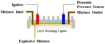
The standard pressure test is designed to inject an explosive gas mixture into the sample and forcibly ignite it to ensure that no damage or deformation of the equipment enclosure occurs during the internal explosion, and to measure the explosion pressure during the explosion. The concentration conditions of the explosive mixture used in the test are shown in Table 4. The test diagram is shown in Figure 2.
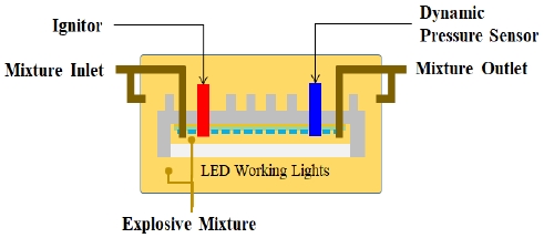
The overpressure test is a test to prove that no damage or change of the equipment occurs when a selected pressure from 1.5 times, 3 times, and 4 times of the pressure determined in the reference pressure test is induced by using water for 10 s. The test diagram is shown in Figure 3, and the routine test frequency changes depending on the pressure level.
The explosive ignition test is a test to inject the same explosive mixture into the inside and outside of the explosion-proof equipment test sample and to prove that the explosive flame caused by the forced ignition inside the sample does not affect the external gas environment. The test diagram is shown in Figure 4.
3. Analytical Evaluation of Explosion-Proof Safety
3.1 Product and analysis modeling overview
The target product of this study was an explosion-proof LED work light that can be applied to explosive areas (explosion-proof areas) and powered by a battery without a power cable. This eliminates the possibility of electric spark (explosion ignition source) caused by cable damage of a metal halide explosion-proof work light that uses wires and can save energy by applying LED as a light source. The specifications of the developed product are shown in Table 5.
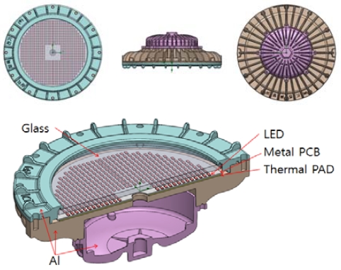
As shown in Figure 5, the 3D model of the product that was developed and used in the analysis of analytical evaluation based on the IEC explosion-proof standards to ensure the explosion safety consists of a light enclosure made of AL 6061, a 10 mm-thick sight glass window, an LED, a metal PCB, and a thermal PAD, which is a silicon series material to transfer heat between the luminaire and PCB interface. The light enclosure consists of three assembled parts. In the analysis, the 6 degrees of freedom displacement constraint was used considering the bolt connection. Similarly, the 6 degrees of freedom displacement constraint was used for the light source part, which is composed of an LED and a metal PCB, considering that the light source is fixed by bolts. Individual LEDs and metal PCBs were modeled as equivalent solids.
3.2 Thermal analysis
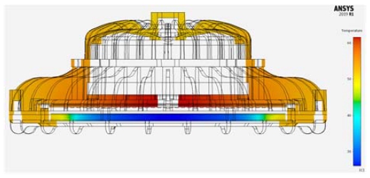
Thermal analysis can be used to estimate the best surface temperature of explosion-proof equipment to assess their suitability for temperature rating. For thermal analysis, ANSYS Discovery AIM 2019 R1, which is a Multiphysics analysis program, was used. Generally, about 30% of the power input to the luminaire is converted to light energy and the rest to thermal energy. Therefore, for 77 W power input, which is 110% of the rated power consumption, the power consumption through heat was set to 53.9 W, and it was assumed that heat is transferred through the LED and the metal PCB (see Figure 5). The analysis showed that the maximum temperature outside the product was 54.3 °C, and the result is shown in Figure 6. The maximum operating temperature based on the ambient temperature, and the correction factor was 74.3 °C, which is suitable for the T6 temperature rating, which requires an operating temperature to be 85 °C or lower.
3.3 Impact resistance analysis
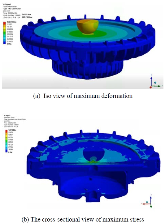
During the impact resistance test, a 1 kg hemispherical collider with a diameter of 25 mm was dropped freely at the height of 0.7 m on an explosion-proof LED work light and collided into the center of a light-transmitting glass. The impact resistance was analyzed using ANSYS Discovery AIM 2019 R1. The gap between the colliding body and the colliding surface, which is the glass surface, was defined as 200 μm. When the collider falls freely at a height of 0.7 m without considering the air resistance, it will reach a speed of 3.7 m/s just before the collision. Therefore, this speed was used as the collision speed. Only the first collision was analyzed, and it was found that the maximum displacement was 1.3 mm, as shown in Figure 7 (a). The maximum stress was found to be 140.1 MPa, as shown in Figure 7 (b). Considering that the yield stress of the aluminum enclosure is 275 MPa and the breaking strength of 10 T of tempered glass is 150 MPa, it was found that the impact resistance of the explosion-proof LED work light meets the explosion-proof standard.
3.4 Drop analysis
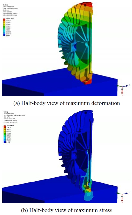
The suitability for the drop test can be evaluated by analyzing the impact that occurs when the explosion-proof equipment is dropped at the height of 1 m onto the horizontal concrete surface. ANSYS AUTODYNE 2019 R1 was used for the drop test. The distance between the explosion-proof LED work light and the ground was defined as 200 μm. When the collider falls freely at the height of 1 m without considering the air resistance, it will reach 4.4 m/s just before the collision. Therefore, this speed was used as the collision speed. Only the first-order collision was analyzed, and the results showed that the maximum displacement was 3.1 mm, and the maximum stress was 310.8 MPa at the end of the explosion-proof LED work light enclosure. The results confirmed that the permanent deformation that occurred during the collision did not impair the operation of the product. In most areas of the enclosure of the explosion-proof LED work light, the stress was found to be less than 200 MPa, which confirmed that the explosion-proof performance was not inhibited or invalidated (See Figure 8).
3.5 Explosion Pressure Analysis
Analysis of the explosion that occurs inside the explosion-proof equipment can be performed to evaluate the safety of the explosion-proof enclosure and to estimate the explosion pressure. ANSYS AUTODYNE 2019 R1 was used to conduct the explosion analysis because it is suitable for solving a significant deformation problem caused by explosions. The TNT equivalency method was used to simulate an explosion event inside the equipment. The TNT equivalent method was proposed in the US Army Technical Manual TM 5-1300. The TNT equivalence method can be used to calculate the equivalent TNT mass that can generate the same amount of energy from an explosion situation [7] [re].
The equation for calculating the TNT equivalent mass by the TNT equivalent method is shown in Equation (1).
| (1) |
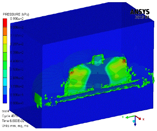
where W is the TNT equivalent mass (kg), μ is the explosion yield, M is the amount of explosive gas leak (kg), and Ec is the amount of thermal energy released per unit mass (kcal/kg) due to the explosion. An explosion of 9.8% hydrogen was converted into TNT equivalents using an explosion yield of 0.5, and it was found that the TNT equivalent mass was 23.9 kg, which was then applied to the explosion analysis using AUTODYN. The analysis results showed that the explosion pressure was 899 kPa and did not impair the safety of the explosion-proof enclosure (see Figure 9).
3.6 Overpressure Analysis
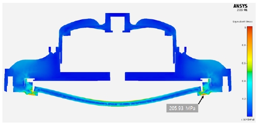
Explosion-proof safety for the overpressure test can be evaluated based on the pressure analysis in which high-pressure is applied inside the explosion-proof equipment to destroy the product. In the actual test, one of the conditions of 1.5 times, 3 times, and 4 times the explosion pressure determined in the determination of explosion pressure is selected to apply the pressure using water and to verify no damage and deformation occurs for more than 10 seconds. In the analysis, 1,350 kPa, which corresponds to 1.5 times the reference pressure, was statically applied to the inner surface and the light-transmitting part of the enclosure. As a result of the analysis, the maximum stress of 205.9 MPa between the light-transmitting part and the enclosure of the product was found, which is less than the aluminum yield strength. However, when 3,560 kPa, which corresponds to 4 times the standard pressure, was applied, a maximum stress of 992.1 MPa was observed, which is higher than the yield strength of the aluminum enclosure.
4. Conclusion
The objective of this study was to evaluate the requirements of the explosion-proof performance of an explosion-proof LED work light analytically. Temperature measurement, high-temperature heat resistance, low-temperature heat resistance, impact resistance, drop test, thermal shock test, reference pressure test, overpressure test, and explosion ignition test, which are required for explosion-proof performance evaluation, were analyzed using ANSYS AIM and ANSYS AUTODYN. Because the results of this study can verify the safety of explosion-proof equipment from the design stage, it is expected that efficient product development will be enabled by reducing prototype production and test evaluation.
Acknowledgments
This study was funded by the Ministry of Trade, Industry, and Energy (MOTIE) and the Korea Energy Technology Evaluation and Planning (KETEP) (Project number: 20182220100690).
Author Contributions
Conceptualization, M. Yoo; Methodology, I. Lee; Software, M. Shin; Validation, M. Yoo and W. Lee; Formal Analysis, I. Lee; Investigation, S. Paek and Y. Seo; Writing—Original Draft Preparation, I. Lee; Writing—Review & Editing, M. Yoo; Visualization, I. Lee; Supervision, M. Yoo; Project Administration, M. Yoo; Funding Acquisition, M. Yoo.
References
- The International Electrotechnical Commission (IEC), “Explosive atmospheres - Part 10-1: Classification of areas - Explosive gas atmospheres,” IEC 60079-10-1, 2015.
- B. J. Ahn, K. H. Jung, and J. K. Rhim, “An accident investigation of fire and explosion case during painting work in the tank of the crude oil carrier,” Journal of the Korean Institute of Gas (KIGAS), vol. 22, no. 3, pp. 20-31, 2018.
-
S. -L. Lee, J. -W. Lee, and G. -H. Kim, “Forecasting the medium term demand of LNG for power generation under the energy transition policy in South Korea,” Journal of Climate Change Research, vol. 10, no. 1, pp. 47-54, 2019.
[https://doi.org/10.15531/KSCCR.2019.10.1.47]

-
J. K. Yeo, J. S. Kim, and Y. M. Yu, “Study on the design and lighting characteristics of 150W LED flood lighting with flameproof enclosure,” Journal of the Korean Institute of Illuminating and Electrical Installation Engineers, vol. 31, no. 11, pp. 1-15, 2017.
[https://doi.org/10.5207/JIEIE.2017.31.11.001]

- The International Electrotechnical Commission (IEC), “Explosive atmospheres - Part 0: Equipment - General requirements,” IEC 60079-0, 2017.
- The International Electrotechnical Commission (IEC), “Explosive atmospheres - Part 1: Equipment protection by flameproof enclosures d,” IEC 60079-1, 2014.
- E. S. Kim and B. H. Choi, Application of Accident Investigation Engineering Simulation, Republic of Korea: Myungjin, 2016 (in Korean).


