Evaluation of the structural integrity and fatigue life of a hydraulic accumulator used for marine diesel engine according to the thread root radius
Copyright ⓒ The Korean Society of Marine Engineering
This is an Open Access article distributed under the terms of the Creative Commons Attribution Non-Commercial License (http://creativecommons.org/licenses/by-nc/3.0), which permits unrestricted non-commercial use, distribution, and reproduction in any medium, provided the original work is properly cited.
Abstract
A hydraulic accumulator can dampen the sudden pressure shock, pulsation, and pressure spike in marine diesel engines. During the operation of a hydraulic accumulator, the thread of its lower shell is subjected to concentrated stress. The purpose of this study is to numerically investigate the structural safety and fatigue life of a hydraulic accumulator according to the thread root radius and friction coefficient using three different models of the lower shells, with thread root radii of 0.1, 0.2, and 0.4 mm. The hydraulic accumulator was analyzed by a static analysis of the lower shell, upper shell, and thread, where stress is concentrated under a 300 bar pressure, using the finite element method. Results shows that the general primary membrane stress and primary bending stress do not exceed the allowable stress. Furthermore, fatigue life evaluation shows that the fatigue life increases with the thread root radius and friction coefficient under severe and abnormal service conditions of a hydraulic accumulator used for marine diesel engines.
Keywords:
Hydraulic accumulator, Finite element method, Thread, Fatigue life, Friction coefficient1. Introduction
1.1 Study background
Marine diesel engines comprise a number of hydraulic devices, such as fuel injection pumps for fuel injection and exhaust valve actuators for exhaust. Such hydraulic devices operate under high pressures and in environments with high pressure shocks and pulsations. As they must supply and maintain a constant pressure for efficient engine system operation and prevent damage from sudden pressure shocks, the application of a hydraulic accumulator is essential.
A hydraulic accumulator comprises a threaded hemispherical lower shell and a threaded hemispherical upper shell. A flexible diaphragm separates fluid from gas.
When a problem occurs in the engine control unit, the hydraulic accumulator enables smooth machine operation by compensating for the appropriate flow rate and pressure. Furthermore, it attenuates and reduces the pressure shocks caused by sudden pressure changes due to the large amount of vibrations and pulsations of a diesel engine.
1.2 Study purpose
Regarding the hydraulic accumulator in this study, which comprises a threaded hemispherical lower shell and a threaded hemispherical upper shell, the thread of the lower shell is subjected to concentrated stress during operation. Such concentrated stress may cause the deformation and damage of the hydraulic accumulator, thereby resulting in an accident. In a previous study, fatigue analysis was conducted on threaded bolts in a cylinder [1] however, in another study, fatigue analysis was conducted on the strength of large bolt geometries, such as accumulators.
The purpose of this study is to establish the design criteria for the lower shell of a hydraulic accumulator subjected to concentrated stress by numerically analyzing the structural safety of the accumulator and evaluating its fatigue life using three different thread root radii of 0.1, 0.2, and 0.4 mm.
2. Model and Analysis Conditions
2.1 Geometry model
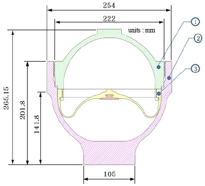
The hydraulic accumulator comprises a threaded hemispherical upper shell and a threaded hemispherical lower shell. Figure 1 shows the simple cross-sectional geometry of the hydraulic accumulator. ① is the upper shell, ② is the lower shell, and ③ is the diaphragm.
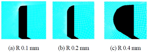
To analyze the structural safety of the hydraulic accumulators according to the thread root radius of the lower shell, three models with different thread root radii (0.1, 0.2, and 0.4 mm) were used as analysis targets.
2.2 Material properties
Both the upper and lower shells of the hydraulic accumulator were made of SCM440 (JIS G4105), an alloy steel. The mechanical properties of SCM440 were provided by a ship engine company according to the application purpose of the hydraulic accumulator [2].
For a conservative approach in analysis, the lowest values among the provided specifications were applied. The mechanical properties of the material are given in Table 1. The allowable stress (S) was the smaller of the tensile strength (Sut)/2.4 and yield strength (Sy)/1.5, in accordance with ASME Boiler and Pressure Vessel Code (BPVC), Sec. VIII, Div. 2, of which the value was 366 MPa [3][4]
2.3 Mesh generation
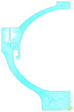
The stress distribution in the threaded section between the upper and lower shells of the hydraulic accumulator is expected to be large. Therefore, a small mesh size of 0.003 mm was created in the threaded section through the mesh test for the calculation of concentrated stress, and relatively less dense meshes were generated in other sections. Figure 2 shows the mesh geometry of the accumulators.
Figure 3 shows the mesh geometry of the threaded section between the upper and lower shells for each of the three hydraulic accumulator models with different lower shell thread root radii (0.1, 0.2, and 0.4 mm).
2.4 Boundary and load conditions
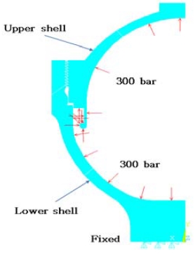
The charging pressure of the hydraulic accumulator was 300 bar, a pressure of 300 bar was applied to the insides of both the upper and lower shells after coupling. As the hydraulic accumulator was assembled and fixed on the block, the bottom of the lower shell was fixed. The boundary and load conditions for analysis are shown in Figure 4. As stress concentration occurred while the upper and lower shell threads of the hydraulic accumulator were in contact; the contact conditions were highly important. This was because the object behavior in the vicinity of the contact area might vary significantly depending on the friction coefficient [5]-[8]. Therefore, for the friction coefficient, which is difficult to measure accurately in actual operating environments among the contact conditions, four values of 0, 0.1, 0.2, and 0.3 were used as analysis variables to analyze the tendency according to the friction coefficient.
3. Structural Analysis Results
3.1 Shell stress according to thread root radius
The equivalent stress analysis results of four cases with 0, 0.1, 0.2, and 0.3 friction coefficients were analyzed for the three lower shell models with thread root radii of 0.1, 0.2, and 0.4 mm.
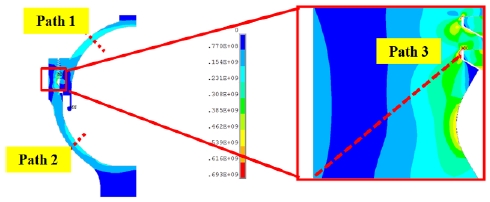
Stress analysis was conducted after designating the section with the lowest thickness in the upper shell as Path 1, that the lowest thickness in the lower shell as Path 2, and that with stress concentration as Path 3. These paths are shown in Figure 5.
For the evaluation of the stress of each path under the design conditions, whether the general primary membrane stress (Pm) exceeded the allowable stress (S) and whether the sum of the general primary membrane stress (Pm) and primary bending stress (Pb) exceeded 1.5 times the allowable stress (1.5S) were analyzed. The stress evaluation criteria are shown in Equation (1).
| (1) |
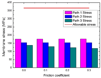
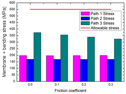
The structural analysis results for a thread root radius of 0.1 mm are shown in Figure 6 and 7. The general primary membrane stress of each path compared with the allowable stress according to the friction coefficient is shown in Figure 6.
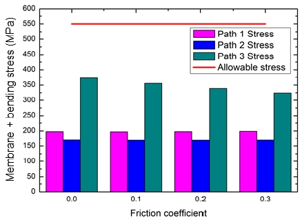
The sum of the primary membrane stress and primary bending stress are shown in Figure 7. The general primary membrane stress and the sum of the general primary membrane stress and primary bending stress did not exceed the allowable stress. Although the effect of the friction coefficient was almost non-existent between the threads, an increase in friction coefficient gradually decreased the stress owing to the effect of restraining the radial displacement of the shell.
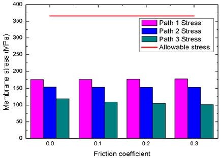
Similarly, in Figure 8 and Figure 9, the structural analysis results for a thread root radius of 0.4 mm are shown. The results were similar to those of the 0.1 mm thread root radius, and it was confirmed that the change in stress of each shell section owing to the thread root radius was small because it was small compared to the shell thickness.
3.2 Stress of thread root according to thread root radius
For the three lower shell models with thread root radii of 0.1, 0.2, and 0.4 mm, the stress distributions at the thread contact area with stress concentration were compared and analyzed.
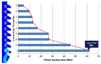
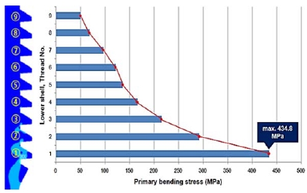
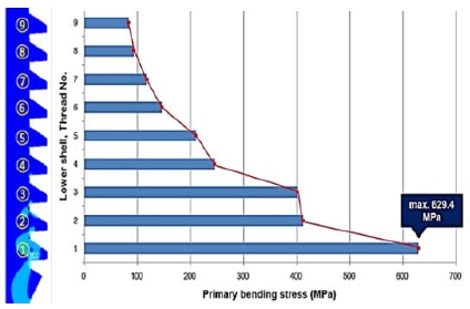
As the total number of threads in the lower shell was nine, numbers from 1 to 9 were determined from the first contact thread with the maximum stress to the last contact thread. The primary bending stress was derived for each thread path. The thread geometry for stress distribution is depicted in Figure 10. The distance between the contact ends of the upper and lower shells as well as the thread root radius of the lower shell with stress concentration are shown.
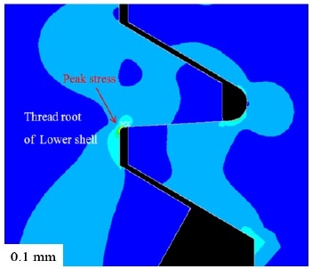
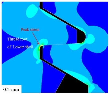
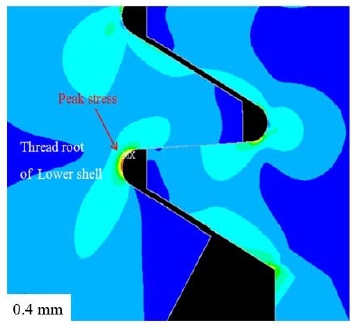
The stress distribution analysis results of Figure 11 to Figure 13 show that the local stress concentration of the 0.1 mm thread root radius was higher than that of the 0.2 mm radius owing to the relatively smaller thread root radius where stress concentration occurred. In the case of the 0.4 mm thread root radius, the peak stress decreased as the stress concentration decreased owing to the increase in the thread root radius; however, the primary bending stress was high because an increase in the length of the thread surface where the contact stress occurred increased the moment length. Therefore, the 0.2 mm thread root radius was judged to be most stable in terms of static strength.
4. Fatigue Life Evaluation
4.1 Fatigue evaluation
It was confirmed that the hydraulic accumulator was structurally stable based on the static failure criteria under a charging pressure of 300 bar, i.e., under the design pressure condition for the three lower shell models with thread root radii of 0.1, 0.2, and 0.4 mm. Because the hydraulic accumulator was under a constant pressure, it was necessary to analyze its fatigue strength.
In this study, a pressure difference of approximately 50 bar is likely to occur owing to the deterioration in the function of the diaphragm applied to the hydraulic accumulator and the severe operating conditions during the voyage. Therefore, it is necessary to evaluate the fatigue life under the cyclic loads of 250–300 bar. For the three lower shell models with thread root radii of 0.1, 0.2, and 0.4 mm, the areas of maximum total stress are shown in Figure 14 - Figure 16, respectively. Fatigue failures may occur in these areas even without large deformations.
The fatigue life was predicted in accordance with ASME BPVC, Sec. VIII, Div. 2 [3]. After calculating the maximum total stress deviation ( ΔSp) for the operating pressure, the alternating stress (Salt) was obtained using Equation (2).
| (2) |
In Equation (2), is the fatigue penalty factor, which is the compensation factor when the deviation of the total stress exceeds the stress tolerance (Sps). The stress tolerance is the larger of three times the allowable stress and twice the yield strength. The stress tolerance of the hydraulic accumulator of this study was 1,280 MPa.
The fatigue penalty factor according to the stress tolerance can be obtained using Equation (3):
| (3) |
where n and m are constants defined in reference [3] according to the material. Table 2 shows the alternating stress obtained considering the maximum stress deviation and fatigue penalty factor under the operating pressure ranging from 250 to 300 bar. The alternating stress decreased as the thread root radius of the lower shell and the friction coefficient increased. The alternating stress was the highest (220 MPa) when the thread root radius was 0.1 mm and the friction coefficient was 0, and it was the lowest (120 MPa) when the thread root radius was 0.4 mm and the friction coefficient was 0.3, indicating an approximately 45% reduction in stress.
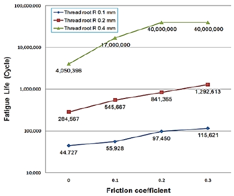
Figure 17 shows the fatigue life calculated by reflecting the alternating stress and fatigue strength curve of the material under an operating pressure ranging from 250 to 300 bar. If pulsations frequently occur under severe pressure conditions, the fatigue life exceeds 110,000 cycles for the 0.1 mm thread root radius and 106 cycles for the 0.2 and 0.4 mm thread root radii. When the 0.4 mm thread root radius was adopted for design, the fatigue life increased; however, the strength decreased in this case owing to the static load.
5. Conclusion
With the thread root of the lower shell of a hydraulic accumulator subjected to concentrated stress during operation, the structures and fatigue lives of three different hydraulic accumulator models with thread root radii of 0.1, 0.2, and 0.4 mm were evaluated, and the following results were obtained.
- 1) First, the structural safety of the three hydraulic accumulator models under the design pressure static condition was confirmed through structural analysis using the finite element method. Under the normal service condition, the fatigue life increased with the thread root radius and friction coefficient. All the three models with thread root radii of 0.1, 0.2, and 0.4 mm maintained an infinite life.
- 2) Under the severe service condition, the fatigue life increased with the thread root radius and friction coefficient. The fatigue life, however, was limited for the 0.1 and 0.2 mm thread root radii, and infinite life was maintained only for the 0.4 mm thread root radius.
- 3) Under the abnormal service condition, the fatigue life increased with the thread root radius and friction coefficient. The fatigue life, however, was limited for all the three models with thread root radii of 0.1, 0.2, and 0.4 mm. The model with the 0.4 mm thread root radius showed the lowest risk of fatigue failure.
- 4) Considering the severe service condition of marine diesel engines, which is different from that of land diesel engines, the 0.4 mm thread root radius was the most stable in terms of fatigue life. The 0.2 mm thread root radius, however, was judged to be optimal considering the static strength.
Acknowledgments
This study was an extension of the Master’s degree thesis by Dong-hyeon Noh (“Evaluation of the Structural Safety of a Hydraulic Accumulator used for Marine Diesel Engine according to the Thread Root Radius,” Graduate School of the National Korea Maritime and Ocean University).
Author Contributions
Conceptualization, D. H. Noh and J. R. Cho; Methodology, D. H. Noh; Software, D. H. Noh; Validation, D. H. Noh and J. . Cho; Formal Analysis, D. H. Noh; Data Curation, D. H. Noh; Writing—Original Draft Preparation, J. J. Kim; Writing— Review & Editing, J. R. Cho and J. J. Kim.
References
- S. -S. Cho, H. Chang, and K. -W. Lee, “Finite element-based fatigue assessment of engine connecting-rod bolts,” Transactions of the Korean Society of Automotive Engineers(KSAE), vol. 16, no. 4, pp. 14-20, 2008 (in Korean).
- MAN Diesel & Turbo, Material specifications of two-stroke, P382-3, Hardened and Tempered Cr-Mo Steel S42Cr1.
- ASME, ASME Boiler and Pressure Vessel Code, Section VIII, Division 2 2017 Edition.
- ASME, ASME Boiler and Pressure Vessel Code, Section III, Part D Properties(Metric) 2017 Edition.
-
K. H. Brown, C. Morrow, S. Durbin, and A. Baca, “Guideline for bolted joint design and analysis: Version 1.0," Sandia National Laboratories, pp. 1-47, 2008.
[https://doi.org/10.2172/929124]

- M. Oliver, “Modeling threaded bolted joints in ANSYS workbench,” ANSYS Advantage, 2012.
-
H. Xu, T. Shi, Z. Zhang, and B. Shi, "Loading and contact stress analysis on the thread teeth in tubing and casing premium threaded connection,” Mathematical Problems in Engineering, pp. 1-11, 2014.
[https://doi.org/10.1155/2014/287076]

- S. G. Yasmin, P. P. Rao, and K. Bommisetty, “3-D finite element analysis of bolted joint using helical thread model,” International Journal of Engineering Research & Technology, vol. 2, no. 12, 2013.

