Experimental study of tip-opening phenomenon in premixed Bunsen flame
Copyright ⓒ The Korean Society of Marine Engineering
This is an Open Access article distributed under the terms of the Creative Commons Attribution Non-Commercial License (http://creativecommons.org/licenses/by-nc/3.0), which permits unrestricted non-commercial use, distribution, and reproduction in any medium, provided the original work is properly cited.
Abstract
The tip-opening phenomenon of Bunsen flame is considered a very important research topic in understanding the laminar flamelet model, as it is a local extinction phenomenon in which various variables act, such as preferential diffusion effect, flame stretch, flame curvature, molecular weight, and equivalence ratio. Several studies have suggested various interpretations to evaluate the criteria for tip opening, the most popular of which is the evaluation method using the Lewis number and Karlovitz number. The Lewis number represented as an imbalance between heat and mass diffusion is generally known to indicate tip opening at Le < 1 in a negative stretched flame. For the Karlovitz number, the ratio of the flow residence time and the characteristic reaction time is defined, and it is known that the tip opening occurs when the reactant is excessively introduced into the flame surface relative to the chemical reaction time. Therefore, in this paper, we suggest a new dimensionless number based on recognized theories to define the tip-opening phenomenon by adjusting the co-flow velocity of a Bunsen flame.
Keywords:
Bunsen flame, Karlovitz number, Lewis number, Mie scattering, Tip opening1. Introduction
With the recent adoption of the International Maritime Organization’s (IMO) regulation for the reduction of greenhouse gas (GHG) emissions from ships, the international shipping industry has shifted its paradigm from ship fuel oils containing large amounts of sulfur to LNG or hydrogen energy, an environmentally friendly fuel. Consistent with this trend, studies are being actively conducted on the propulsion system of ships and gas turbines that can use eco-friendly fuel. In particular, gas turbines are expected to satisfy most of IMO’s acceptance criteria for GHG emission from ships, unlike diesel engines using heavy oil, but it is difficult to regard the gas turbines to be in a proper commercialization stage. The reasons are as follows: first, the supply and price system is not stable with several uncertainties. Second, it is difficult to rule out the risk of fire or explosion. Finally, as it is difficult to consider that domestic technology has reached maturity, for the next five years, we would have to rely completely on imports to meet market demand.
At present, several factors hinder the technological development of domestic gas turbines, but the biggest obstacle is the technology to control combustion instability occurring in gas turbines [1]. Combustion instability is caused by vibration, noise, and combustion failure in the combustion system. In particular, fluctuations in flame temperature due to local combustion failure may lead to thermoacoustic instability, which can cause combustor damage and explosion [2]-[5]. Therefore, with the increasing interest in the gas turbine market, the demand for a combustion technology that can maximally suppress local flame extinction is also increasing.
Combustion failure arises owing to various causes that can be classified into three major factors in terms of combustion engineering. First, combustion failure can be caused by stretch, where local flame extinction occurs if fuel supply and chemical reactions are not properly balanced in time [6][7]. Second, they can be caused by the imbalance of heat and mass diffusion [8]. Finally, local heat loss in the combustion system can also cause combustion failure [9].
The aforementioned phenomenon of combustion failure can be understood with the flame tip-opening phenomenon generally occurring in Bunsen flames [6]-[8]. Because the Bunsen flame corresponds to negative stretch, the flame has a concave shape with reference to the reactants thereby the flame surface is compressed. Here, due to the imbalance of heat and mass diffusion, the center part of the concave flame causes thermal focusing or mass dissipation. If the Lewis number (Le), which is defined as the ratio of heat and mass diffusion coefficients, is greater than unity, thermal focusing occurs on the unburned gas side, and the flame propagation velocity is higher than the adiabatic flame velocity due to the increased reactant temperature. If Le is less than unity, mass dissipation occurs toward the concave flame surface and the flame temperature is lower than the adiabatic flame temperature due to the decay of the reactant inflow to flame surface. Here, as the flame curvature increases, the rate of decrease in the flame temperature gradually increases, and eventually, local flame extinction occurs. This is defined as the flame tip-opening phenomenon [6]-[8].
Another dimensionless number as a criterion for evaluating flame tip-opening is the Karlovitz Number (Ka), which is defined as the ratio of characteristic flow time and characteristic reaction time. Therefore, when the reactants are not sufficiently supplied to the flame surface with regard to the characteristic reaction time, the flame is locally extinguished and the flame tip-opening phenomenon occurs due to the decreased chemical reaction rate.
T. M. Vu et al. [10] noted that, although the flame tip-opening phenomenon is independent of the nozzle exit velocity, Ka, which is used as the evaluation indicator, is affected by the nozzle exit velocity. To address this problem, he newly defined the local Karlovitz number (hereinafter KaL) as follows, using the inverse relationship between the nozzle exit velocity and the flame radius of curvature.
| (1) |
where α is the heat diffusion coefficient, is the nozzle exit velocity, and R is the radius of curvature. If the newly defined KaL is used as the evaluation indicator for the flame tip-opening phenomenon, the value becomes constant regardless of the nozzle exit velocity. Accordingly, Tran succeeded in the observation of flame tip-opening under the condition KaL < 1.72 regardless of the gas composition, and proposed the value 1.72 as the threshold value for the occurrence of the flame tip-opening phenomenon [2]. Tran’s research identified the independent relationship between the nozzle exit velocity and the flame tip-opening phenomenon included in KaL, however did not derive the physical interpretation of the flame radius of curvature.
Therefore, in this study, experiments to control Le and KaL were performed to investigate the flame tip-opening phenomenon. Le was changed through various gas compositions and KaL was controlled by changing the gas composition and co-flow velocity. In particular, increasing the co-flow velocity of the air composition in a rich premixed flame results in a relatively decreased preferential diffusion effect at the flame tip, because it has the effect of a partial supply of insufficient oxidizer. Therefore, the experiment was conducted with the prediction of the result of suppressing or reducing the flame tip-opening due to the additional supply of oxidizer in the rich premixed flame. In addition, even though the flame tip is closed, as the flame radius of curvature decreases by a strong stretch with the increase in the co-flow velocity, we aim to derive the physical interpretation of the flame radius of curvature in KaL.
2. Experimental Setup
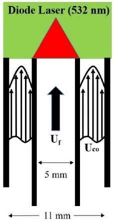
Figure 1 shows a schematic diagram of the co-flow burner and experimental set up used in this experiment. The nozzle and coaxial internal diameters were 5 and 11 mm, respectively, and a flame was formed by injecting a premixed gas containing fuel, oxidizer, and diluent gas from the centrally located nozzle. The coaxial nozzle formed a fully developed flow to maximize preferential diffusion throughout the flame surface and the co-flow velocity was increased from 0 to 50 cm/s. The gas composition used in the experiment is shown in Table 1. Propane (C3H8) and methane (CH4) were used as fuel to produce the flame tip-opening phenomenon. For the diluent gas, nitrogen (N2) and carbon dioxide (CO2) were used to control Le. The equivalence ratio was varied between rich condition (rich, Φ = 1.6) and lean condition (lean, Φ = 0.7) in the experiment. The nozzle exit velocity (Uj), flame spread velocity (SL), and diluent molar ratios were varied by gas composition and all the flame lengths used in the experiment were set to 2.8 cm. The molar ratio was obtained using the following Equation (2).
| (2) |
The equivalence ratio of lean/rich condition was not selected proportionally because the flame tip-opening phenomenon is generally observed under the condition of equivalence ratio of 1.5 or higher for hydrocarbon-based fuels [10], and for lean conditions, flame extinction occurs under the condition of equivalence ratio of 0.5 or lower.
Therefore, the equivalence ratio was randomly selected for the open and closed conditions of the flame tip. Furthermore, in the case of CH4 flame, the dilution of nitrogen yielded the Le values of 0.95 and 1.05 in the lean and rich conditions, respectively, indicating no significant difference in Le according to the equivalence ratio. This case did not satisfy the experimental purpose, and it was excluded from the experiment.
For the visualization of the flame tip-opening phenomenon, we obtained CH chemiluminescence (CH*) and OH chemiluminescence (OH*) images using an ICCD camera and applied the Mie-scattering method to acquire the flow field information inside the flame. TiO2 (2.5 μm) seeded particles were used for the Mie scattering method, and a diode laser (2.5W, 532 nm) in the visible range was used. Using the flow field visualization information obtained through the Mie-scattering method, the pathline was extracted with MATLAB code.
3. Results and Discussion
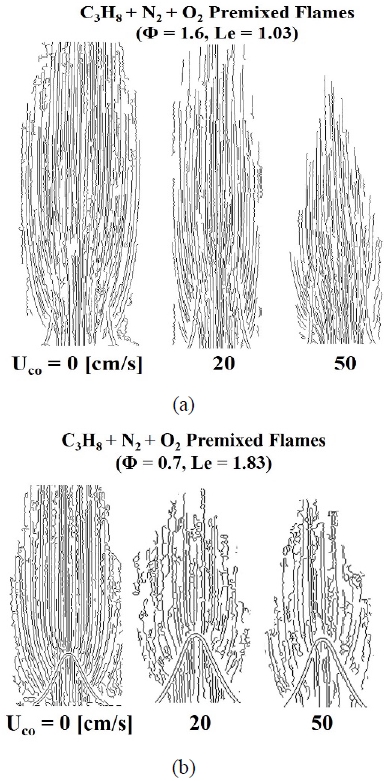
Figure 2 shows the rich and lean conditions as (a) and (b), respectively, with various visualization techniques for the C3H8-N2 premixed flame. Determination of flame tip-opening was defined as the time at which both the following criteria were satisfied:
- (1) when the signals of CH* and OH* chemiluminescence shown in rows 1 and 2 of Figure 2 are clearly weak compared with the other flame surfaces at the flame tip;
- (2) based on the image extracted by the Mie-scattering method shown in row 4 of Figure 2, when the pathline of the seeded particles leaks more than 5% of the nozzle area in the axial direction from the flame tip.
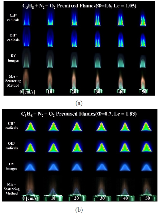
Instant images of C3H8-N2 premixed flames with various visualization methods at (a) Φ = 1.6 and (b) Φ = 0.7
Figure 2 (a) shows the flame image of the C3H8-N2 premixed flame under the rich condition (Φ = 1.6) according to the co-flow velocity change. As shown in the figure, the CH* and OH* signal measurements show that the tip remained open even in the basic flame condition with a co-flow velocity of 0 cm/s.
Figure 2 (b) shows the results of experiments under the lean fuel condition (Φ = 0.7) for the C3H8-N2 premixed flame. Because the basic flame condition was Le = 1.83, the CH* and OH* images confirmed that the flame tip was closed. After increasing the co-flow velocity, because the insufficient chemical species was the fuel, preferential diffusion due to the oxidizer introduced from the outside was not observed.
In other words, despite a sufficient supply of oxidizer, the flame length was constant and the flame curvature did not show any clear change. In addition, the intensities of the CH* and OH* signals at the flame tip were measured to be approximately the same.
To clarify this point, the pathline of the seeded particles for the open and closed flame tips is shown in Figure 3 using MATLAB-code-based image processing. Figure 3 (a) is the pathline of the seeded particles when the flame tip is opened. As shown in the figure, when the co-flow velocity was 0 cm/s, a large amount of seeded particles leaked out from the flame tip in the axial direction. However, as the co-flow velocity increased, the opened flame tip was closed slowly and the amount of seeded particles axially leaking out from the tip was significantly reduced. It is believed that the flame curvature increased due to the increased preferential diffusion by supplying oxygen, which is the insufficient chemical species.
Figure 3 (b) shows the pathline of the seeded particles when the flame tip is closed. The pathline shape of the basic flame was almost identical to the pathline shape when the co-flow velocity was increased. The seeded particles were discharged in a vertical direction from the surface in regions other than the flame tip.
Figure 4 shows the experimental results of changing the diluent gas to CO2. Figure 4 (a) shows the flame images with various visualization techniques under the rich condition (Φ = 1.6) of the C3H8-CO2 premixed flame. In this case, as Le = 0.77, the basic flame with the co-flow velocity 0 cm/s corresponds to the case where the tip is opened, and the visualization experiment also showed the same result. After gradually increasing the co-flow velocity, the flame tip was observed to be gradually closed through the CH* and OH* images. As with the previous experimental results, the flame length was reduced by the preferential diffusion with the additional supply of oxidizer as the co-flow velocity increased.
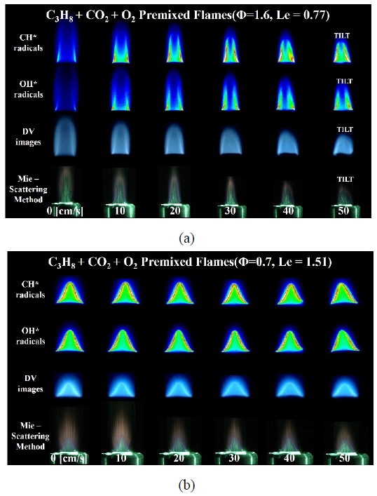
Instant images of C3H8-CO2 premixed flames with various visualization methods at (a) Φ = 1.6 and (b) Φ = 0.7
Figure 4 (b) shows the visualized experimental results for the lean flame (Φ = 0.7) with CO2 as the diluent gas. In this case, the closed flame was observed as expected because Le = 1.51 in the basic flame. As with the C3H8 lean premixed flames diluted with N2, no significant changes in flame length, CH* and OH* luminescence, and flame curvature were observed as the co-flow velocity increased. The present results also correspond to the lean condition, which is believed to indicate that preferential diffusion did not occur with the increase in the co-flow velocity.
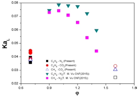
After obtaining the flame curvature with increasing co-flow velocity for C3H8 and CH4 premixed flames, the results are presented in Figure 5 along with the results of a previous study [10], as a function of KaL and the equivalence ratio.
The hollow symbol here indicates that the flame tip is open. First, the results of previous studies showed that the flame tip-opening phenomenon was observed at KaL < 0.04, which, as described in the Introduction section, well describes the physical phenomenon of the flame tip-opening, which does not depend on the nozzle exit velocity.
In the results of this study, the nitrogen-diluted C3H8 premixed flame showed a tendency where the flame tip was closed slowly by increasing the co-flow velocity and reducing the flame curvature in the rich condition, but a fully closed tip was not observed. Nevertheless, when the maximally closed flame curvature (the hollow black square) was calculated and expressed as KaL, the value was less than 0.04. However, in the lean condition (full black square), the flame tip was observed to be still closed, even though a KaL of 0.04 or less was obtained due to the reduced flame curvature as the co-flow velocity increased. In addition, it was not possible to derive a constant threshold value independent of gas composition because in the range 0.035 < KaL < 0.045, the representations were mixed with CH4 premixed flames (hollow triangle) in the lean conditions where flame tip-opening was observed. Therefore, the new results of this study confirm that flame tip-opening is not observed below a certain value of KaL, as proposed in the previous study [10].
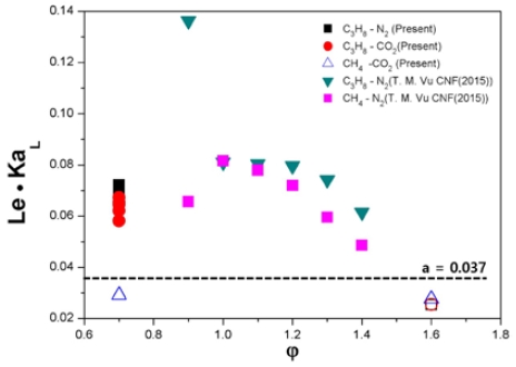
To clarify this point further, another indicator for evaluating the flame tip-opening phenomenon, Le, in combination with KaL, is shown as a function of the equivalence ratio in Figure 6. The symbol notation method is the same as that used in Figure 5. As shown in the figure, flame tip-opening is clearly determined with reference to Le · KaL = 0.037. Therefore, it was confirmed through this experimental study that both KaL and Le should be reflected in the evaluation of the flame tip-opening phenomenon.
4. Conclusion
To evaluate KaL and Le as indicators to define the flame tip-opening phenomenon, an experimental study was performed to control the gas composition and co-flow velocity in a Bunsen burner. The following is a summary of the results obtained in this study.
- 1) The flame tip-opening phenomenon could be observed at Le < 1 due to imbalance between heat and mass diffusion.
- 2) When the flame tip was opened in the rich condition, owing to the increasing preferential diffusion caused by increasing the co-flow velocity, the flame tip closed slowly and the flame length decreased with the increase in the local flame speed, but we could not observe a completely closed flame tip.
- 3) When the flame tip was closed in the lean condition, the increase in the co-flow velocity resulted in negligible changes in the flame curvature, flame length, and flame intensity due to no preferential diffusion effect.
- 4) Through evaluating KaL based on the flame curvature obtained through various visualization techniques, the threshold value that can define the flame tip-opening phenomenon could not be derived. However, it was confirmed that the presence of flame tip-opening was clearly defined based on the result of combining Le with KaL.
Acknowledgments
This work was supported by the Technology Innovation Program (20005750, Commercial Development of Combustion System Control Technology for Minimizing Pollutant with Multiple Analysis) funded by the Ministry of Trade, Industry & Energy (MOTIE, Republic of Korea).
Author Contributions
Conceptualization, S. H. Yoon; Methodology, S. H. Yoon; Formal Analysis, Y. W. Ju; Investigation, Y. W. Ju; Resources, Y. W. Ju; Data Curation, Y. W. Ju; Writing—Original Draft Preparation, Y. W. Ju; Writing—Review & Editing, S. H. Yoon; Visualization, Y. W. Ju; Supervision, S. H. Yoon; Project Administration, S. H. Yoon; Funding Acquisition, S. H. Yoon.
References
- J. S. Oh and Y. B. Yoon, “Combustion instability in gas turbine engines,” Journal of the Korean Society of Propulsion Engineers, vol. 12, no. 4, pp. 63-77, 2008 (in Korean).
-
S. H. Yoon, T. J. Noh, and O. Fujita, “Onset mechanism of primary acoustic instability in downward-propagating flames,” Combustion and Flame, vol. 170, pp. 1-11, 2016.
[https://doi.org/10.1016/j.combustflame.2016.05.008]

-
S. H. Yoon, T. J. Noh, and O. Fujita, “Effects of Lewis number on generation of primary acoustic instability in downward-propagating flames,” Proceeding of the Combustion Institute, vol. 36, no. 1, pp. 1603-1611, 2017.
[https://doi.org/10.1016/j.proci.2016.09.013]

-
J. H. Choi, S. H. Yoon, J. W. Park, D. G. Park, and C. H. Lee, “A study on thermo-acoustic instability of down-wardpropagating hydrocarbon flames in a tube,” Transactions of the Korean Society of Mechanical Engineers B, vol. 44, no. 1, pp. 1-12, 2020 (in Korean).
[https://doi.org/10.3795/KSME-B.2020.44.1.001]

-
J. H. Choi, S. C Park, Y. S. Jun, Y. J Chun, K. H. Han, and S. H. Yoon, “Dynamic behaviors of acoustic instability according to Lewis number in downward-propagating premixed flames,” The Korean Society of Combustion, vol. 23, no. 3, pp. 10-18, 2018 (in Korean).
[https://doi.org/10.15231/jksc.2018.23.3.010]

-
C. K. Law, D. L. Zhu, and G. Yu, “Propagation and extinction of stretched premixed flames,” Proceedings of the Combustion Institute, vol. 21, no. 1, pp. 1419-1426, 1988.
[https://doi.org/10.1016/S0082-0784(88)80374-6]

-
S. Ishizuka, “An Experimental study on extinction and stability of stretched premixed flames,” Proceedings of the Combustion Institute, vol. 19, no. 1, pp. 327-335, 1982.
[https://doi.org/10.1016/S0082-0784(82)80204-X]

-
M. Mizomoto, Y. Asaka, and S. Ikai, “Effects of preferential diffusion on the burning intensity of curved flames,” Proceedings of the Combustion Institute, vol. 20, no. 1, pp. 1933-1939, 1985.
[https://doi.org/10.1016/S0082-0784(85)80692-5]

-
T. H. Kim, O. B. Kwon, J. Park, S. I. Keel, J. H. Yun, and J. H. Park, “A study on flame extinction in oxymethane combustion,” The Korean Society of Combustion, vol. 20, no. 4, pp. 34-41, 2015.
[https://doi.org/10.15231/jksc.2015.20.4.034]

-
T. M. Vu, M. S. Cha, B. J. Lee, and S.-H. Chung, “Tip opening of premixed bunsen flames: Extinction with negative stretch and local Karlovitz number,” Combustion and Flame, vol. 162, no. 4, pp. 1614-1621, 2015.
[https://doi.org/10.1016/j.combustflame.2014.11.022]


