Fundamental study on cool thermal storage characteristics using trimethylolethane
Copyright ⓒ The Korean Society of Marine Engineering
This is an Open Access article distributed under the terms of the Creative Commons Attribution Non-Commercial License (http://creativecommons.org/licenses/by-nc/3.0), which permits unrestricted non-commercial use, distribution, and reproduction in any medium, provided the original work is properly cited.
Abstract
In this study, trimethylethanol (TME) was selected as a hydrate-generating material, and its applicability as a cool thermal heat storage material was examined. In general, to develop a material that performs better than water (ice), which is typically used as a cool thermal storage material for cooling, TME hydrates were selected. Their basic thermal properties including the solidification point, specific gravity, latent heat, and viscosity were investigated according to their concentration were investigated. An experimental apparatus and a heat transfer model were developed to investigate the heat transfer characteristics of the TME hydrates, and a calculation method was considered.
Keywords:
Cool thermal storage material, Trimethylolethane, Heat transfer, Thermal properties, Hydrate1. Introduction
In recent years, with the spread and increased use of air conditioning systems, the widening gap of power demand between daytime and nighttime has become a problem. To reduce such a gap in power demand, technologies such as thermal storage systems, which apply cool thermal storage functions using excess power stored at night for daytime air conditioning, have been introduced and implemented. In general, when a cool thermal storage fluid is cooled in a refrigerator, a higher phase change temperature of the cool thermal storage fluid results in a smaller amount of energy required for cooling. However, water or ice, which is currently used as a cool thermal storage medium, must have a low melting temperature of 0.01 °C and requires cooling and storing from room temperature to 0.01 °C. In this regard, hydrates are attracting attention as a new cool thermal storage medium, with their high phase change temperature of 10 – 20 °C and high latent heat. The use of hydrates as a cold thermal storage medium can reduce the size of thermal storage tanks or cold thermal pipes compared with using cold water as a thermal storage fluid, while significantly reducing the power of cold energy generation compared with ice.
In this study, we examined trimethylolethane (hereinafter referred to as TME) as a hydrating agent to produce hydrates and investigated its applicability as a cool thermal storage medium.
2. General Properties of TME
TME, represented by the formula C5H12O3, is an odorless, nontoxic, alcohol-based white crystalline sugar with three primary hydroxyl groups. Its basic thermal properties are shown in Table 1 [1].
In addition, when TME is employed as a cool thermal storage material, it is used in the form of a solution, and hydrates are generally formed as crystals; however, fine hydrate crystals can be formed in a slurry phase with water or a solution depending on the production conditions. A slurry refers to a mixture of two phases, i.e., a fine solid phase and a liquid phase, and the hydrate crystal in the solid phase is called the hydrate slurry. As a hydrate slurry exhibits high fluidity, cold heat can be transferred directly by injecting the slurry into a pipe; furthermore, because it contains latent heat as well as sensible heat, a high thermal storage density can be secured. Many studies have applied hydrate slurries to air-conditioning systems [2]-[6]. Using these hydrates, large hydrate crystals can be produced where they are formed in stationary water and not in the form of a slurry. However, cooling a mixture of water molecules and molecules such as TME while mixing produces hydrate slurries.
3. Thermal Properties of TME hydrate
3.1 Solidification point of TME hydrate
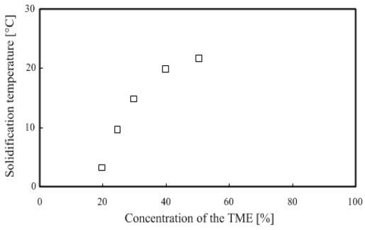
In general, when cooling a cool thermal storage material, a higher phase change temperature of the material results in a smaller energy required for cooling. Therefore, when developing a new latent heat storage material, it is necessary to seek a material with a higher phase change temperature than ice, which is currently used as a thermal storage medium. Therefore, the solidification point was measured according to the concentration of TME.
In this experiment, 300 ml of TME set to a certain concentration was injected into a beaker, and a T-type thermocouple was installed to monitor the temperature change while cooling up to the point of phase change. Subsequently, TME was heated until the solid phase disappeared. This process was performed repeatedly.
Figure 1 shows that the TME hydrate concentration is 20 - 30 wt % in the phase change temperature range of 0 – 15 °C, making it suitable for use in actual air-conditioning systems.
3.2 Specific gravity of TME hydrate
To determine the density of TME hydrates, their specific gravity was measured.
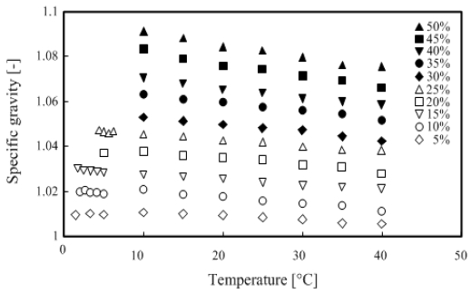
In this experiment, 500 ml of TME hydrates of any concentration was prepared in a beaker, and the hydrates were injected into a cylindrical container with an internal diameter of 40 mm and a height of 300 mm. The specific gravity was measured using a hydrometer. Meanwhile, the measurement temperature range was set from the solidification point of the TME hydrate with concentration between 5 – 50 wt % to 40 °C. The relationship between temperature and specific gravity is shown in Figure 2.
As shown in Figure 2, the specific gravity of TME hydrates is higher at any concentration compared with distilled water. In addition, the specific gravity increased with the concentration, but it decreased with increasing temperature.
3.3 Latent heat of TME hydrates
To use TME hydrates as a cool thermal storage material, it is necessary to measure the thermal storage calories, and the latent heat of TME hydrates was measured using differential scanning calorimetry (DSC).
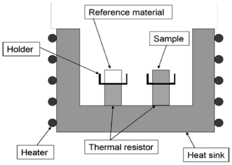
Typically, DSC is used to measure the energy input difference between a sample and a reference as a function of temperature while changing it according to a program to control the temperature of a sample and a reference. The curve obtained from the function is called a DSC curve.
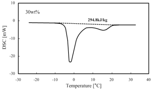
The measured results of a 30 wt% TME hydrate with 5 °C/min heating rate are shown in Figure 4 (see Figure 3 for reference).
The DSC curve in Figure 4 shows a straight line parallel to the x-axis when the temperature difference between the TME hydrate and reference (alumina) is approximately zero. This line is called the base line. Furthermore, a curve that starts from the base line and returns to the base line is called a peak. At this time, with the base line as a center, when the curve moves upward, it corresponds to the heat dissipation, whereas a downward curve means heat absorption. Therefore, as shown in Figure 4, the area created by the connection between the points moving down from the base line, the peak point, and the point returning to the base line represent the latent heat of fusion.
As shown in Figure 4, the peak representing ice melting appears at approximately - 2 °C and the peak of TME hydrate melting is at approximately 17 °C.
In fact, the data used for cool thermal storage is the latent heat of TME hydrates; therefore, it is necessary to separate the latent heat of fusion of TME hydrates by subtracting the latent heat of fusion of ice from the total amount of latent heat of fusion. The latent heat of TME hydrates can be obtained from the total latent heat by determining the ratio of the TME hydrate to the remaining water molecules without undergoing hydration in 1 mol. Equation (1) calculates the TME latent heat from the measured total latent heat:
| (1) |
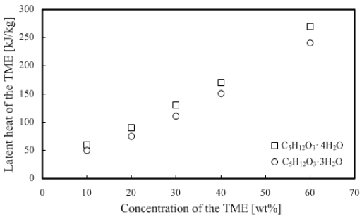
Here, L is the overall latent heat [kJ/kg], LTME the latent heat of TME [kJ/kg], LWater the water latent heat [kJ/kg], C the concentration of TME hydrate, n the hydration number, MWater the water molecular weight, and MTME the molecular weight of TME. In addition, because the TME hydration number can be 3 or 4, Figure 5 shows the result calculated with hydration numbers 3 and 4. As shown from the results, the latent heat increases in proportion to the increase in the concentration of TME hydrates, and we can deduce that the difference in hydration numbers 3 and 4 can be obtained from the difference in n, as shown in Equation (1).
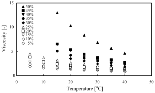
3.4 Viscosity of TME hydrates
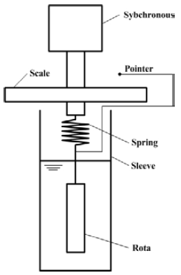
When transporting TME hydrates, their viscosity was measured to investigate the flow characteristics of the fluid. Figure 6 shows the schematics of the rotation viscometer used for the measurement in this study.
The rotation viscometer is a measuring instrument that allows a rotor to be connected to a synchronous motor such that the rotor rotates through a spring in the sample and the viscous resistance torque can be measured by the rotating rotor. In addition, the relationship between shear speed and shear torque can be obtained by measuring the inner diameters of the rotor and the sleeve.
The rotation viscometer was used for measurements under the conditions of 5–50 wt % TME concentration and temperature range of 5–40 °C.
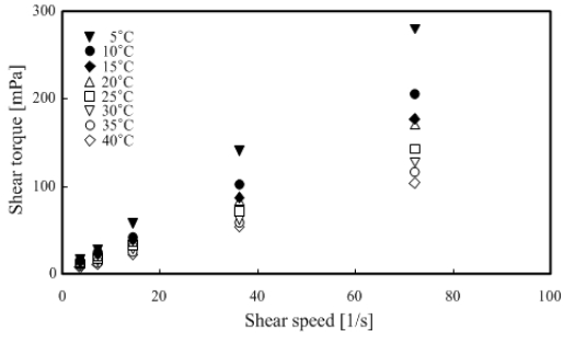
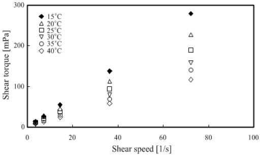
Figure 7 and Figure 8 show that the TME hydrates were a Newtonian fluid because the shear torque was proportional to the shear speed at any temperature range. The measured results were organized and summarized based on the relationship between temperature and viscosity, as shown in Figure 9.
4. Cold thermal storage basic experiment of TME hydrate slurry
4.1 Experimental apparatus
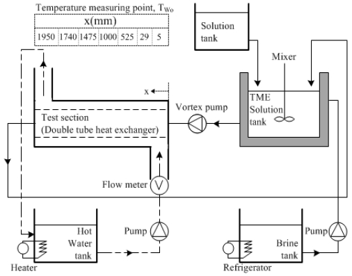
Figure 10 shows the schematics of a cool thermal storage experimental apparatus using TME hydrates.
The experimental apparatus comprised a double tube heat exchanger, which was a test section, a circulation system for TME hydrate slurries, a system for hot water, and a TME-hydrate-slurry generating section.
A stainless steel tube with full length L = 2000 mm, inner tube inner diameter di = 14 mm, inner tube thickness ti = 1.2 mm, outer tube inner diameter do = 37.1 mm, and outer tube thickness to = 2.8 mm was used for the double tube heat exchanger. In addition, to measure the temperature Tw of the tube outer wall surface in the test section, a T-type thermocouple (thickness of 0.3 mm) was installed in seven points in the horizontal direction of the test section and four points in the upper, lower, left, and right directions along the inner tube circumferential direction.
The circulation system of the TME hydrate slurry comprises a hydrate slurry storage tank, which is a TME hydrate slurry generator, a solution tank to store TME hydrates and control the solid phase ratio of the hydrates, a vortex pump, and stainless steel test section piping.
In the hydrate slurry storage tank, a propeller mixer with three blades was installed, and mixing was performed in the tank during hydrate slurry generation and supply.
The hot water circulation system comprises a thermostat, magnetic pump, float-type flow meter, and flow control bypass.
4.2 Reliability of experimental apparatus
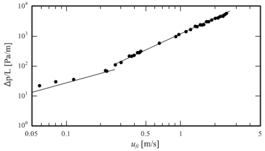
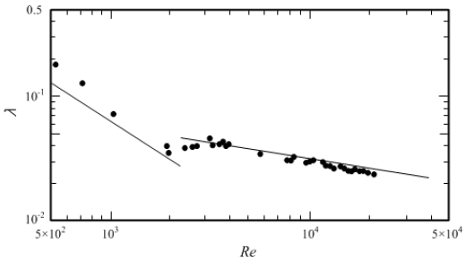
To confirm the reliability of the experimental apparatus, the pressure loss was measured by flowing water at 5 °C in the test section. Figure 11 shows the relationship between flow rate and pressure loss, and Figure 12 shows the relationship between Reynolds number and pipe friction factor. A comparison between the theoretical equation and Blasius’ empirical equations for the laminar flow of water represented by the solid lines in the graphs of Figure 11 and Figure 12 shows an average difference of 1.5% in the relationship between flow rate and pressure loss and 3.8% for the relationship between Reynolds number and pipe friction factor. The difference can be considered to indicate that this experimental apparatus is reliable.
4.3 Calculation of local heat transfer coefficient
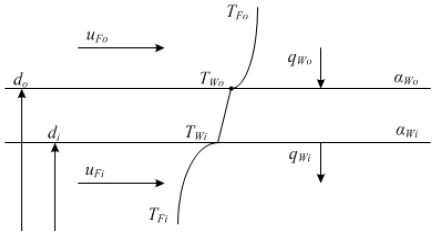
Figure 13 shows a heat transfer model to calculate the local heat transfer coefficient. For the double tube test section used in this experiment, the pipe used as an actual heat exchange was estimated, and the value of di = 14 mm was set for the pipe inside the test section. However, as it was difficult to measure the inner wall surface temperature TWi directly by setting the local heat transfer coefficient αWi as the value at the inner wall surface Wi of the inner tube owing to the structure of the experimental apparatus, the inner wall surface temperature TWi and local heat transfer coefficient αWi were obtained by measuring the outer wall surface temperature TWo from the inner tube outer wall surface temperature Wo, as follows.
It can be considered that the local heat transfer coefficient αWo on the outer wall surface does not change regardless of the local heat transfer coefficient αWi on the inner wall surface if the outer pipe (annulus) flow rate uFo is constant. Here, the local heat transfer coefficient on the inner wall surface was first calculated by introducing the previous empirical equation (Dittus–Boelter's equation) to calculate the local heat transfer coefficient αWo at the outer wall surface. Subsequently, the local heat transfer coefficient αWi at the inner wall surface was calculated using the calculated local heat transfer coefficient αWo on the outer wall surface.
In addition, the local heat transfer coefficient αWi on the inner wall surface can be regarded as exhibiting conditions close to the isothermal heating condition when the outer pipe (annulus) flow rate uFo is sufficiently high, with the temperature difference ΔTFo between the inlet and outlet of the annulus approximately 0.5–1 K and inner wall surface temperature TWi indicating an almost constant value in the horizontal direction of the test section. Therefore, the empirical equation for turbulent flow heat transfer under isothermal heating conditions was used to calculate the local heat transfer coefficient αWi. αWi can be calculated from Equation (3) by applying the Dittus–Boelter equation, which is a turbulent flow heat transfer equation in a circular tube, as shown below (Equation (2)), as the heat transfer coefficient on the inner wall surface when cold water flows in the inner tube.
| (2) |
| (3) |
Here, Nu is the Nusselt number, Re the Reynolds number, Pr the Prandtl number, and kf the heat transfer coefficient of water.
Next, assuming that the heat flux qWo at the outer wall is generated only in the radial direction, the heat flux qWo can be calculated from Equation (4):
| (4) |
Here, kp is the heat transfer coefficient of a circular tube. Therefore, the local heat transfer coefficient αWo on the outer wall can be calculated by Equation (5):
| (5) |
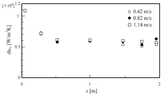
Figure 14 shows the change in the local heat transfer coefficient αWo in the horizontal direction of the test section on the outer wall surface, with the inner tube flow rate uFi calculated by the method above as a parameter. In this case, the measurement was performed under constant conditions of annulus flow rate uFo = 0.52 m/s and annulus inlet hot water temperature TFo_in = 293 K. As shown in Figure 14, even if the inner tube flow rate uFi was changed, similar values of local heat transfer coefficient αWo were obtained. From these results, the local heat transfer coefficient αWo, which can be calculated in the same manner, was considered to have provided valid results. Therefore, the local heat transfer coefficient αWi on the inner wall surface was calculated using the calculated local heat transfer coefficient αWo on the outer wall surface and the outer wall surface temperature TWo measured at the time of the heat transfer coefficient experiment.
The heat flux qWo on the outer wall can be expressed as follows:
| (6) |
Therefore, regarding the heat flux qWi on the inner wall, when we assume that heat flow is generated in the radial direction only, it can be obtained using Equation (7) and Equation (8).
| (7) |
when Equation (7) is reorganized to heat flux qWi on the inner wall surface, it can be expressed as Equation (8).
| (8) |
In addition, the inner wall surface temperature TWi can be calculated by Equation (9) as follows:
| (9) |
Here, kp is the heat transfer coefficient of the circular tube. From the equation above, the heat transfer coefficient αWi on the inner wall surface can be organized and represented as shown in Equation (10) and Equation (11) below.
| (10) |
Equation (10) can be arranged as Equation (11) to obtain the heat transfer coefficient αWi on the inner wall surface.
| (11) |
Herein, we consider only the calculation method of heat transfer coefficient αWi on the inner wall surface; for the actual experiment, a subsequent paper will provide the discussion and analysis of the results.
5. Conclusion
In this study, to develop a cool thermal storage material that can be used for actual air-conditioning system, we investigated the basic thermal properties and heat transfer characteristics of the developed cool thermal storage material. Furthermore, we verified the reliability of the experimental apparatus and the calculation method of the local heat transfer coefficient, which was devised in this study for examining the heat transfer characteristics of the material. The following conclusions were obtained in this study.
- (1) As a result of performing the solidification point experiment according to the TME concentration, the TME concentration was identified to be 20–30 wt % TME hydrates in the temperature range of 0–15 °C, a range applicable to actual air-conditioning systems.
- (2) Latent heat was measured using DSC, and because the data used for cool thermal storage was the latent heat of TME hydrates, the latent heat of fusion of ice was subtracted from the overall latent heat of fusion to yield the latent heat of fusion for TME hydrates.
- (3) By examining the relationship between shear torque and shear speed for measuring the viscosity of TME hydrates, it was determined that TME hydrates are a Newtonian fluid because the shear torque was proportional to shear speed at any temperature range.
- (4) A cool thermal storage system was developed to investigate the heat transfer characteristics of TME hydrates; to verify the reliability of the devised experimental apparatus, the relationship between Reynolds number and pipe friction factor was analyzed by measuring the pressure loss from flowing water at 5 °C in the test section. Consequently, it was confirmed that the difference from the theoretical equation was 1.5 % on average, and 3.8% on average with the Blasius empirical equation in water laminar flow, indicating that the results obtained demonstrated good agreement, thereby verifying the reliability of the experimental apparatus.
- (5) A heat transfer model was proposed for the calculation of the local heat transfer coefficient of the double tube heat exchanger, which was the test section of the experimental apparatus, and the method of calculating the local heat transfer coefficient at the inner and outer wall surfaces of the tube was presented. For the calculation of the local heat transfer coefficient on the outer wall surface, valid results were obtained through the analysis of experimental data. However, for the local heat transfer coefficient on the inner wall surface, as TME hydrates are currently in the development stage, the results obtained through actual experiments will be published in a subsequent paper.
References
-
M. Yamazaki, C. Sasaki, H. Kakiuchi, Y. T. Osano, and H. Suga, “Thermal and structural characterization of trimethylolethane trihydrate”, Thermochimica Acta, Vol. 387, no. 1, pp. 39-45, 2002.
[https://doi.org/10.1016/S0040-6031(01)00821-8]

-
R. Koyama, Y. Arai, Y. Yamauchi, S. Takeya, F. Endo, A. Hotta, and R. Ohmura, “Thermophysical properties of trimethylolethane(TME) hydrate as phase change material for cooling lithium-ion battery in electric vehicle,” Journal of Power Sources, Vol. 427, pp. 70-76, 2019.
[https://doi.org/10.1016/j.jpowsour.2019.04.055]

-
M. Darbouret, M. Cournil, and J. M. Herri, “Rheological study of TBAB hydrate slurries as secondary two-phase refrigerants,” International Journal of Refrigeration, vol. 28, no. 5, pp. 663-671, 2005
[https://doi.org/10.1016/j.ijrefrig.2005.01.002]

-
H. Kumano, T. Hirata, and T. Kudoh, “Experimental study on the flow and heat transfer characteristics of a tetra-n-butyl ammonium bromide hydrate slurry (first report: Flow characteristics),” International Journal of Refrigeration, vol. 34, no. 8, pp. 1953-1962, 2011
[https://doi.org/10.1016/j.ijrefrig.2011.06.002]

-
H. Kakiuchi, M. Yabe, and M. Yamazaki, “A study of trimethylolehane hydrate as a phase change material,” Journal of Chemical Engineering of Japan, vol. 36, no. 7, pp. 788-793, 2003
[https://doi.org/10.1252/jcej.36.788]

- Y. S. Indartono, A. Suwono, A. D. Pasek, and A. Christantho, “Application of phase change material to save air conditioning energy in building”, ASEAN Engineering Journal Part A, vol. 3, no. 2, pp. 46-53, 2013.


