Effect of reboiler layout on steam generation
1Ph.D Candidate, Department of Mechanical Engineering, Korea Maritime & Ocean University, Tel: 051-410-4953 mha1234@naver.com2Director, MMK Corporation, Tel: 051-256-5162 mmk5161@naver.com
Copyright ⓒ The Korean Society of Marine Engineering
This is an Open Access article distributed under the terms of the Creative Commons Attribution Non-Commercial License (http://creativecommons.org/licenses/by-nc/3.0), which permits unrestricted non-commercial use, distribution, and reproduction in any medium, provided the original work is properly cited.
Abstract
A steam boiler that supplies steam is generally made of steel, and a boiler compound is added to the working fluid to prevent surface corrosion. However, the added compound contaminates the steam. To solve this problem, a boiler constructed of a primary boiler comprising a boiler compound in a closed system and a reboiler that is formed of corrosion-resistant materials has been researched. The primary boiler transfers steam to a reboiler and generates clean steam from the received steam. Because the primary boiler is composed of a closed system, the internal material of the reboiler is relatively devoid of thermal stress; however, it has the disadvantage of requiring additional costs and reducing the efficiency, because the reboiler is separated from the primary boiler. In this study, the effects of the layout of a reboiler on the steam generation in an integral boiler system consisting of a primary boiler and the reboiler are analyzed. The effects of the steam inlet and outlet heights, tilt, and rotational angle on the performance of the reboiler are investigated. The steam generation performance is the best under the conditions of inlet and outlet heights 40–50 mm, tilt angle 15°, and rotation angle 0°.
Keywords:
Reboiler, Steam generation, In/outlet position1. Introduction
A boiler is a device for generating and supplying steam or hot water by placing water or fruit (special oils) in a closed container and heating it with a combustion gas. Boilers are primarily classified as steam and hot water boilers.
A typical steam boiler is composed of steel or galvanized steel. Thus, a boiler compound is added to prevent internal surface corrosion. Corrosion-resistant materials are not appropriate as boiler interior materials because they are susceptible to the thermal stress caused by the heat of combustion. The disadvantages of a boiler using a boiler compound include periodic replacement of the entire steam water to resolve the electrolyte concentration in the boiler compound and feed water due to the continuous steam generation. Other disadvantages are heat loss during the replacement, cost incurred by the continuous use of the boiler compound, and contamination of the steam by the boiler compound. To generate clean steam using the conventional boilers, a heat-exchanger-type reboiler formed of corrosionresistant materials is installed and employed. This reboiler serves as a heat exchanger, which generates clean steam by heat exchange between hot steam and water.
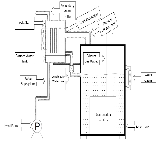
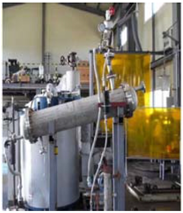
The reboiler considered in this study is formed of corrosionresistant materials and generates clean steam from the steam received from the primary boiler possessing a closed system (Figure 1). Although a boiler compound is added to the primary boiler supplying the steam, the electrolyte concentration caused by the steam generation does not occur, and the complete replacement of the steam water is not necessary. This is because the primary boiler possesses a closed system. The boiler system is cost-effective because there is neither steam water waste nor heat loss. Further, it is relatively devoid of the shortened service life and frequent failures caused by the thermal stress. This is because the reboiler, which is composed of corrosion-resistant materials, receives heat through steam. The boiler system is also economical because no cost is incurred by various factors in the additional installation.
There are different types of heat exchangers: plate, shell-andtube, and micro heat exchangers. In addition, research has been conducted on various heat exchangers [1]-[4]. Among them, shell-and-tube heat exchangers are the most suitable for a reboiler, because they have a structure appropriate for heat exchange with a high-pressure fluid [5]. Studies have been performed on several shell-and-tube heat exchangers [6]-[9].
For shell-and-tube heat exchangers, numerous factors have to be considered, including the head geometry, inlet and outlet positions of the heat-exchange fluid, baffle size, and spacing; therefore, it is difficult to understand their flow and heat transfer characteristics [7]. In addition, evaporative heat exchangers, which use the latent heat of vaporization, exhibit higher performances than typical practical heat exchangers; however, the research on them is not sufficient because it is difficult to analyze their heat transfer processes [10].
In this study, the effects of the inlet and outlet positions, tilt angle, and rotation angle of a reboiler filled with water on the steam generation performance were compared and analyzed to propose the optimal reboiler geometry and conditions.
2. Mathematical Models and Calculation Conditions
2.1 Mathematical models
The governing equations used for the flow calculation are as follows.
The continuity equation is given in Equation (1).
| (1) |
The momentum equations are given in Equation (2) and Equation (3).
| (2) |
| (3) |
The energy equation is expressed in Equation (4).
| (4) |
Above, U is the velocity vector, SM is the momentum source term, τ is the stress tensor, δ is the unit matrix, SE is the energy source term, and λ is the thermal conductivity.
A phase change model was employed to generate steam from water. The equation for the model is as follows.
The mass generation rate, Γ, is obtained from Equation (5) - Equation (10).
| (5) |
| (6) |
| (7) |
| (8) |
| (9) |
| (10) |
Above, is the mean radius of condensate, r is the Kelvin–Helmholtz critical radius, σ is the surface tension at temperature T, S is the supersaturation ratio, T0 is the condensate temperature, qc is the evaporation factor, Kb is the Boltzmann constant, Mm is the mass of the molecule, and θ is the non-isothermal correction factor.
2.2 Calculation conditions
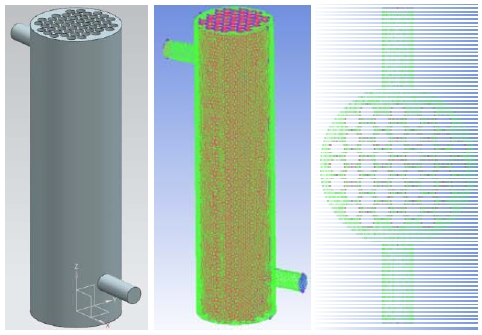
The reboiler used for the analysis was a shell-and-tube type. The shell had a 100-mm diameter and a 345-mm height, and the tube had a 9.8-mm diameter and an 11.3-mm pitch. The tube pattern was a 60° triangle. The inlet and outlet had a 20-mm diameter and a 100-mm height. Figure 3 presents the model and meshes used for the calculation. The meshes had tetrahedral structures, and the minimum number of meshes satisfying the minimum quality of 0.3 was 1.5 million. The SST (Shear Stress Transport) model was used as the turbulence model. y+ was less than 10, and it was less than 1 around the tube.
In a reboiler, steam flows on the tube side, and the water is maintained at a constant level on the shell side. To analyze this, the phase change model of Ansys CFX 13 was employed, and the tube side was set as a heat wall with a temperature of 175 ℃. To input the steam pressure condition, the initial value and the outlet pressure were set as 5 bar. Further, for the analysis, the volume fractions of air and water were set as 40% and 60% (note: the initial value was set based on an MMK corporation 1-ton boiler), respectively. Steam was generated only by a phase change. The inlet was under a load of 0.02 kg/s, at which the water was neither excessive nor disproportionate in all the cases, and the temperature was set as 30 ℃. All the cases were compared based on the steady-state analysis.
Table 1 lists all the cases. It is assumed that the height direction of both the inlet and outlet is the X-axis and that the shell height direction of the reboiler is the Z-axis. Then the inlet and outlet heights represent the distances from both ends of the Z-axis of each shell to the inlet and outlet, respectively. The tilt angle (°) is the angle rotated with respect to the X-axis direction. The rotation angle (°) is the angle rotated with respect to the Z-axis direction. In cases 1–4, the inlet/outlet heights are increased from 20 to 50 mm in 10-mm increments at tilt angle 90° and rotation angle 0°. The analysis was conducted from 20 mm onward because the inlet and outlet were in contact with both ends of the shell when the inlet/outlet height was 10 mm. In cases 4–9, the tilt angle is increased from 0° to 90° in 15°-increments at inlet/outlet height 50 mm and rotation angle 0°. The analysis was conducted from 15° onward because the outlet was submerged in water, which was continuously discharged when the tilt angle was 0°. In cases 9–15, the rotation angle is increased from 0° to 90° in 15°-increments when the inlet/outlet height is 50 mm and the tilt angle is 15°.
3. Results and Discussion
3.1 Effect of the inlet/outlet height
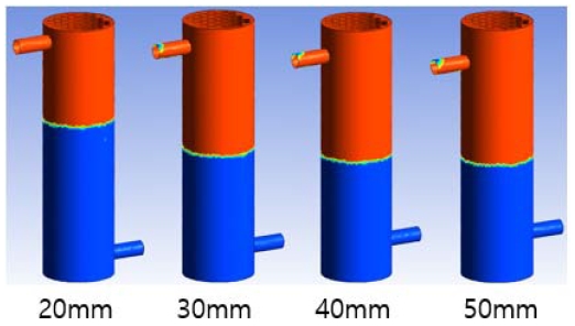
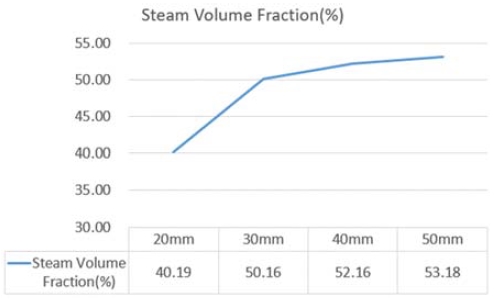
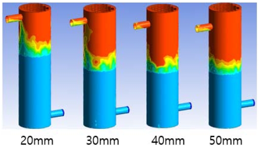
Figure 4 and Figure 5 present the steam area and steam volume fraction variation, respectively, with the inlet/outlet height. As the height increased, the steam area increased. The steam volume fraction was the highest (53.18%) when the height was 50 mm and lowest (40.19%) when it was 20 mm.
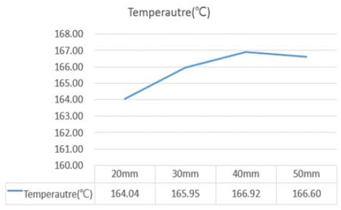
Figure 6 and Figure 7 display the temperature and average temperature distributions versus the inlet/outlet height, respectively. The area of the steam that reached the maximum temperature of 175 ℃ was the smallest and the largest when the height was 20 mm and the 40 mm, respectively. The average temperature was the highest (166.92 ℃) and the lowest (164.04 ℃) when the height was 40 mm and 20 mm, respectively.
When the steam occupies a large area in the steady state, it suggests that a large amount of steam is generated owing to the excellent heat exchange performance when water is supplied at a constant flow rate. Because the average temperature is also high when water is supplied at a constant flow rate, it indicates an active heat exchange. Therefore, it is expected that the steam generation performance will be the highest when the inlet/outlet height is 40 or 50 mm.
3.2 Effect of the heat exchanger tilt angle
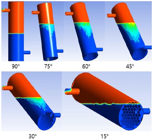
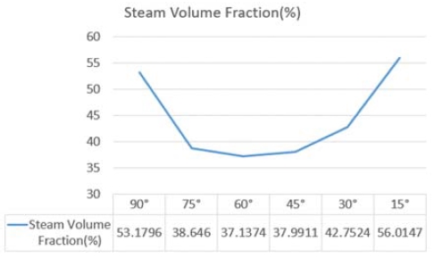
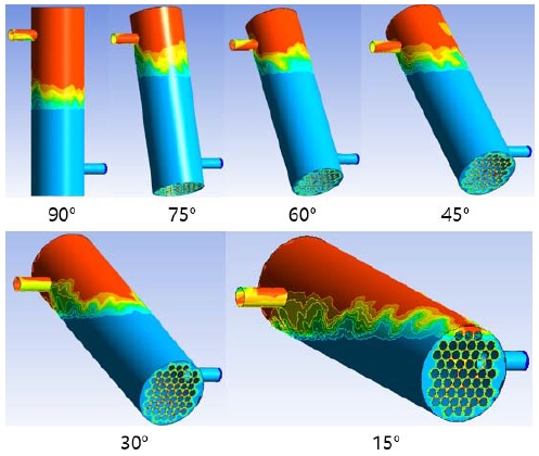
Figure 8 and Figure 9 present the steam area and the steam volume fraction variation with the tilt angle. As the tilt angle decreased, the steam area decreased and then increased again when the angle was smaller than 60°. The steam volume fractions were the highest (56.01% and 53.18%) when the tilt angles were 15° and 90°, respectively, and the lowest (37.14%) when the tilt angle was 60°.
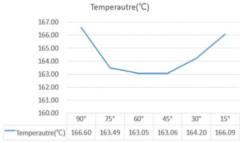
Figure 10 and Figure 11 show the temperature and average temperature distributions according to the tilt angle, respectively. As the tilt angle decreased to 60°, the area that reached the maximum temperature of 175 ℃ decreased and then again increased. The average temperature also exhibited the same trend. It was the highest (166.6 ℃) when the tilt angle was 90° and the lowest (163.05 ℃) when it was 60°. A slightly different average temperature (163.06 ℃) was observed when the tilt angle was 45°.
When water was continuously supplied, tilt angles of 90° and 15° led to superior steady-state temperatures and steam areas compared to those at other angles. It is expected that the amount of steam generated will be the largest at 15° because the steam area is large at 15° even though the average temperature is high, i.e. 90°.
3.3 Effect of the heat exchanger rotation angle
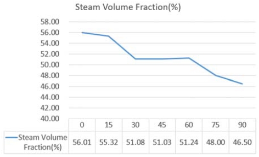
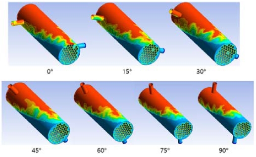
Figure 12 and Figure 13 exhibit the steam area and steam volume fraction according to the rotation angle, respectively. The steam area did not significantly change; however, it showed a tendency to decrease as the angle increased. The steam area was the largest (56.01%) when the angle was 0° and the smallest (46.50%) when it was 90°.
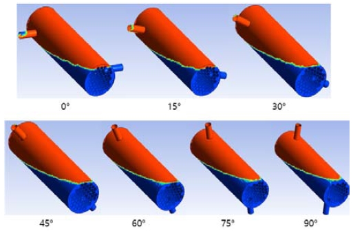
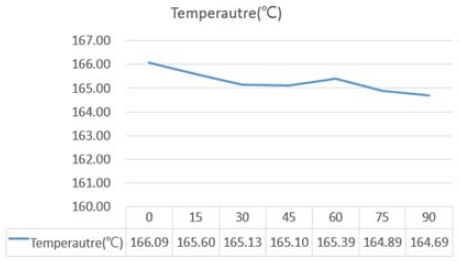
Figure 14 and Figure 15 present the temperature and average temperature distributions versus the rotation angle, respectively. The area that reached the maximum temperature of 175 ℃ decreased as the angle increased. The average temperature also continuously decreased, except at 60°. The temperature was the highest (166.09℃) at 0° and lowest (164.69℃) at 90°.
In regard to the influence of the heat exchanger rotation angle, the steam generation performance was the highest when the input and output positions were horizontal.
4. Conclusion
In this study, the effect of a reboiler layout on the steam generation performance was analyzed. The drawn results are summarized as follows:
- 1) As the steam inlet/outlet height of the reboiler increased, the steam area and temperature increased, and similar values were observed when the height exceeded 40 mm.
- 2) When the heat exchanger tilt angle was 90° or 15°, the steam area and temperature were the highest. They were the lowest when the angle was 45°.
- 3) Regarding the rotation of the inlet and outlet, the amount of steam generated was the largest when the directions of the inlet and outlet were horizontal and was the smallest when they were vertical.
Summarizing, the optimal steam generation performance was achieved when the inlet/outlet height was 40 – 50 mm, tilt angle was 15°, and inlet and outlet were horizontal.
Acknowledgments
This research was supported by the Technology Development Project funded by the Ministry of SMEs and Startups in 2018 [No. S2658345].
Author Contributions
Conceptualization, M. R. Ryu, K. H. Park and Y. J. Lee; methodology, M. R. Ryu; Software, M. R. Ryu; Formal Analysis, M. R. Ryu; Investigation, M. R. Ryu and Y. J. Lee; Resources, M. R. Ryu; Data curation M. R. Ryu; Writing-Original Draft Preparation, M. R. Ryu; Writing-Review & Editing, K. H. Park; Visualization, M. R. Ryu; Supervision, K. H. Park; Project Administration, K. H. Park; Funding Acquisition, K. H. Park.
References
-
J. H. Park, S. Y. Cho, J. S. Lee, S. R. Lee, S. H. Kim, G. H. Lim, J. W. Seo, and J. H. Kim, “An experimental study on performance evaluation for development of compact steam unit applied with hybrid plate heat exchanger,” Journal of the Korean Society of Marine Engineering, vol. 41, no. 4, pp. 296-301, 2017.
[https://doi.org/10.5916/jkosme.2017.41.4.296]

-
H. J. Kim, H. S. Lee, J. I. Yoon, C. H. Son, and Y. K. Jung, “A numerical study on heat transfer and pressure drop of plate heat exchanger using at seawater air conditioning with the variation of channel spaces,” Journal of the Korean Society of Marine Engineering, vol. 38, no. 6, pp. 704-709, 2014.
[https://doi.org/10.5916/jkosme.2014.38.6.704]

-
L. Zhao and J. K. Yoon, “A study on heat transfer and pressure drop characteristics of plain fin-tube heat exchanger using CFD analysis,” Journal of the Korean Society of Marine Engineering, vol. 38, no. 6, pp. 615-624, 2014.
[https://doi.org/10.5916/jkosme.2014.38.6.615]

- C. H. Baek, J. -S. Lee, S. -W. Kim, D. -W. Kim, K. -S. Song, and Y. -C. Kim, “Study on evaporation heat transfer characteristics of plate heat exchangers for 120 steam generation,” Proceedings of the Society Of Air-Conditioning And Refrigerating Engineers Of Korea Winter Annual conference, pp. 371-374, 2014.
- B. J. Kim, D. E. Kim, Y. S. Park, and J. H. Kim, “CFD analysis on characteristics of heat transfer in shell and tube heat exchanger,” Proceedings of the Korean Society of Mechanical Engineers(KSME) Spring and Autumn conference, pp. 2780-2781, 2012.
- T. W. Kang, J. R. Bae, W. J. Choi, M. K. Jeon, and Y. H. Yoon, “The evaluation of heat transfer performance in shell-and-tube evaporator using high-flux tubes,” Proceedings of the Society of Air-conditioning and Refrigerating Engineers of Korea(SAREK) Annual conference, pp. 1100-1103, 2011.
- S. I. Kim, K. H. Park, and W. P. Chun, “The performance in shell-and-tube heat exchangers with configuration and surface characteristics of tube,” Proceedings of the Korean Society of Mechanical Engineers (KSME) Spring and Autumn conference, pp. 2316-2321, 2008.
- B. S. Kim and G. W. Song, “A study on the temperature distribution of heat exchanger tube by the characteristic variation of boiler combustion gas”, Proceedings of the Korean Society of Mechanical Engineers (KSME) Spring and Autumn conference, pp. 33-34, 2012.
- J. J. Kwon, J. H. Park, I. K. Kim, and Y. S. Kim, “Study on heat transfer coefficient test of evaporator tube in shell and tube heat exchanger by shape”, Proceedings of the Society of Air-conditioning and Refrigerating Engineers of Korea (SAREK) Summer conference, pp. 1107-1112, 2006.
- C. H. Song, D. Y. Lee, and S. T. Ro, “Performance comparison between evaporative and sensible heat exchangers through theoretical analysis”, Proceedings of the Society of Air-conditioning and Refrigerating Engineers of Korea (SAREK) Annual conference, pp. 3-7, 2000.

