A new method to analyse the speed power performance of operating ships and its implementation
Copyright © The Korean Society of Marine Engineering
This is an Open Access article distributed under the terms of the Creative Commons Attribution Non-Commercial License (http://creativecommons.org/licenses/by-nc/3.0), which permits unrestricted non-commercial use, distribution, and reproduction in any medium, provided the original work is properly cited.
Abstract
Ship operators need means to analyse their fleet’s performance in order to maintain their competitiveness. Important decisions such as voyage planning and scheduled maintenance, are all made based on a ship’s performance. However, there is no reliable method to estimate a ship’s performance. ISO19030 provides a means to measure the changes in performance but is only applicable to data collected over a relatively long period of time and is unsuitable for comparing the performance of sister ships. In this study, we implemented a software to analyse a ship’s performance. To meet the ship operator’s requirements, a new speed power performance analysis method based on ISO15016:2015 is proposed. The proposed method first evaluates the added or decreased resistance due to the environmental changes including wind, waves and water density first. Then, the measured shaft power is corrected by direct power method and finally corrected to reference displacement for comparison. The results of its implementation, a software called SPA, and its application to two ships, a 176K bulk carrier and an 8600TEU container carrier, are described herein.
Keywords:
Ship performance analysis (SPA), ISO15016:2015, ISO19030, Speed power performance1. Introduction
Ship operators need a means to analyse their fleet’s performance in order to maintain their competitiveness. Important decisions such as voyage planning and scheduled maintenance are all based on the ship’s performance. However, there seems to be no reliable means to estimate a ship’s performance. The most widely used measurements to estimate a ship’s performance are fuel consumptions, but even with weather filtering, it is difficult to identify how much fuel consumption is due to environmental forces such as wind and waves, and how much is due to the ship’s performance itself.
In 2016, ISO19030 was developed in order to prescribe practical methods for measuring changes in ship specific hull and propeller performance [1]. The emphasis was laid on practical methods, and many analysis techniques, such as calculating added resistance due to waves, were not included in the standard, as there was no practical means of collecting the data necessary to apply such techniques at the time. Instead, filtering and averaging were introduced instead to deal with environmental effects that were not accounted for in the standard. The result was a practical method that measures a ship’s performance with the limitations that it can only be used to compare ship specific changes relatively and unsuitable for comparing different ships, with rather coarse time resolution (the averaging period should be at least 3 month or more and typically a year). However, ship operators need a means by which they can analyse their fleet’s performance for each leg of the journey and often day by day. Decisions to increase a ship’s efficiency are made day to day and three months averaged value of a ship’s performance is far too late and coarse to be useful in a decision-making process.
There have been some previous research on applying ISO19030 methods for the analysis of a ship’s performance. Researches outlined in [2]-[5] are notable examples. All authors commonly express concerns regarding filtering performance, and regret that the ISO19030 cannot provide means of comparing performance between ships or within shorter periods.
There has been other research that has tried to analyse a ship’s performance using different approaches. Notably, J. Park et al. [6] used machine learning to predict a decrease in performance due to fouling. D. Gundermann et al. [7] used a simple regression model to obtain speed and power relationship for cases where no reference data are available. M. Jeon et al. [8] used a meta-regression model to predict fuel consumption. However, all these attempts did not consider a physical model of the wind and waves, and were only based on previous data; therefore, they cannot reflect changes in the operational profile or environment well.
This paper implements a software to analyse a ship’s performance. To meet a ship operator’s requirements, a new analysis method based on ISO15016:2015 is proposed [9]. ISO15016:2015 is the amended standard of the ship speed trial analysis method. Its accuracy objective of 2% in shaft power and 0.1knots in speed was verified from many sources during its development process as it is being used in contracts and mandatory regulations such as the reference speed in EEDI calculations [10]. ISO15016:2015 was also considered during ISO19030 development and many parts of ISO19030, such as wind correction, were directly referenced. The results of its implementation and application to two ships, a 176K bulk carrier and 8600TEU container, are described herein.
2. Analysis method
2.1 Overall process
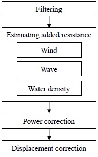
The overall process of the new proposed method is basically the same as ISO19030 and ISO15016:2015. First, unprocessable data, such as when the ship changes direction or moving in shallow water, are removed by filtering. Then increases in resistance due to environmental forces are estimated by the same method used in ISO15016:2015. Then, these resistance increases are used to correct power using the direct power method used in ISO15016:2015. For the purpose of comparison, the analysis results are further corrected to standard displacement. The overall analysis procedure is summarised in Figure 1, and Table 1 summarizes the difference between the proposed method and ISO9030.
2.2 Filtering
In ISO19030, filtering is used to remove outliers and only leave the part of the data when the ship is steadily cruising. However, as noted in B. J. Park et al. [11], the filtering in ISO19030 may have unwanted effects. In ISO15016:2015, unfiltered data is applied as the speed trial is only conducted in a very calm environment and few measurements are taken. The analysis method used in this paper employs very simple filters to avoid any unwanted effects:
- ① Remove when speeds are too low or high. Usually the speed range in the model test is used as a reference and any data with the speed outside the range is discarded.
- ② Remove data when rudder angle is larger than 5° to remove when changing direction.
- ③ Remove data when the ship is operating in shallow water.
2.3 Estimating added resistance
Resistance increase due to wind, waves and differences in water density are estimated with the same method as used in ISO15016:2015. For wind resistance, ISO19030 and ISO15016:2015 use the same method. A detailed method for calculating the resistance increase due to wind is presented in Annex C of ISO15016:2015.
Wave resistance, it was not included in ISO19030 as no practical means of measuring wave parameters were available. However, as noted in B. J. Park et al. [12] there exist publicly available wave data from sources such as the National Oceanic and Atmospheric Administration (NOAA). ISO15016:2015 in Annex D includes STAWAVE II and a theoretical method for wave resistance calculation, but because the theoretical method requires more detailed ship geometry data and requires more time for calculation, STAWAVE II, even with its limitation of only being able to calculate waves within ±45° of the ship’s heading, is a more practical method to use.
An increase in resistance due to differences in water density can be calculated as detailed in Annex E of ISO15016:2015 from the water temperature, which is also available from weather services even if the ship is not equipped to record such data.
2.4 Power correction
Once all resistance increases are estimated, they are used to correct the measured power value. The required correction for power is calculated using Equation (1).
| (1) |
where:
ΔP is the required correction for power in watts;
ΔR is the total resistance increase in newtons;
Vs is the ship’s speed through the water in metres per seconds;
PDm s is the measured delivered power in the operating condition in watts;
ηDm s is the propulsive efficiency coefficient in the operating condition;
ηDid is the propulsive efficiency coefficient in the ideal condition.
ISO15016:2015 uses a load variation test to identify the ratio between the propulsive efficiency coefficient in the operating condition and in the ideal condition as shown in Equation (2).
| (2) |
where:
ξP is derived considering the load variation effects as described in Annex J of ISO15016:2015;
Rid is the resistance in the ideal condition in newtons.
However, as most ships does not perform a load variation test during a model test, if the results of the load variation test are non-existent, then ratio can be set to 1.
The corrected power is calculated by Equation (3).
| (3) |
where:
PDid is the corrected delivered power in the ideal condition.
Current correction is not included in the new method. The current correction method in ISO15016:2015 assumes that the measurements are taken in the same geographical location and therefore current can be expressed as a periodic function dependent on time. However, for operating ships, geographical location and the current affecting the ship’s performance are always changing. Also, by using speed through water instead of speed over the ground, current effects are already partially considered in the speed measurements themselves.
2.5 Displacement correction
Each leg of the journey of an operating ship has different displacements, and to compare the analysis results, the differences in displacements has to be taken into account. This is achieved by first defining standard displacements for typical loading conditions such as laden and ballast for bulk carriers and 80% or 90% displacements for container carriers, and then using the displacement correction method in ISO15016:2015 to correct power for standard displacements. After displacement correction, analysis results can be compared with each other and even with the model test or sea trial results, if such data is available for the same loading conditions.
3. Implementation
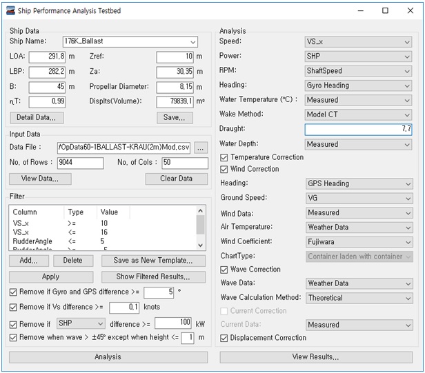
A software implementing the analysis method described in section 2 called SPA (Ship Performance Analysis Software) was developed. SPA implements all functions necessary to handle a large amount of data, which is collected during the operation of the ship. Particular care is given to its practical application and the key functions are listed as below:
- ① Fast processing of a large amount of data using an internal database.
- ② Define custom filters to be applied as per the user’s requirements.
- ③ Use of templates for ship definition, data column definition and filter definition, which will enable a user to reuse well-defined templates for subsequent analysis.
- ④ Custom select which measurements to use for speed, power, heading and environmental correction.
- ⑤ Review the results of applying filters, and the analysis results, in a table format inside the software.
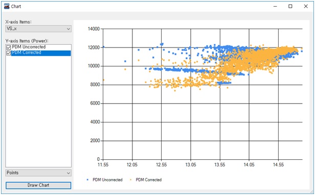
- ⑥ Show the speed power graph inside the software for a quick review of the analysis results.
- ⑦ Output detailed analysis results in csv format for further analysis when necessary.
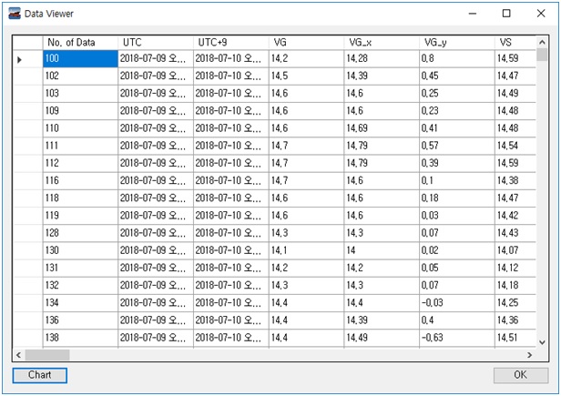
The main window of SPA is shown in Figure 2. The imported data, the results of applying filters, and the final analysis results can all be reviewed within the software as shown in Figure 3. It is also possible to quickly review the analysis results with a speed power graph as shown in Figure 4.
The data used in the SPA software have already been collected by the ship operators. Table 2 summarises the input data for the SPA software. The output from the SPA software after analysis includes full calculation results in .csv format, which can be used later by the user. Table 3 is a list of the output data.
4. Application
This section describes the application results of the SPA software to the operational data recorded onboard a 176K bulk carrier and an 8600TEU container carrier. Each analysis was performed over one leg of a journey, where the same loading conditions were maintained, and the duration was approximately two to three weeks for the bulk carrier, and several days to a week for the container carrier.
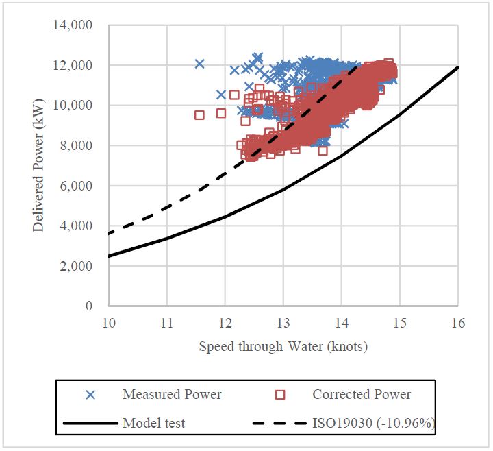
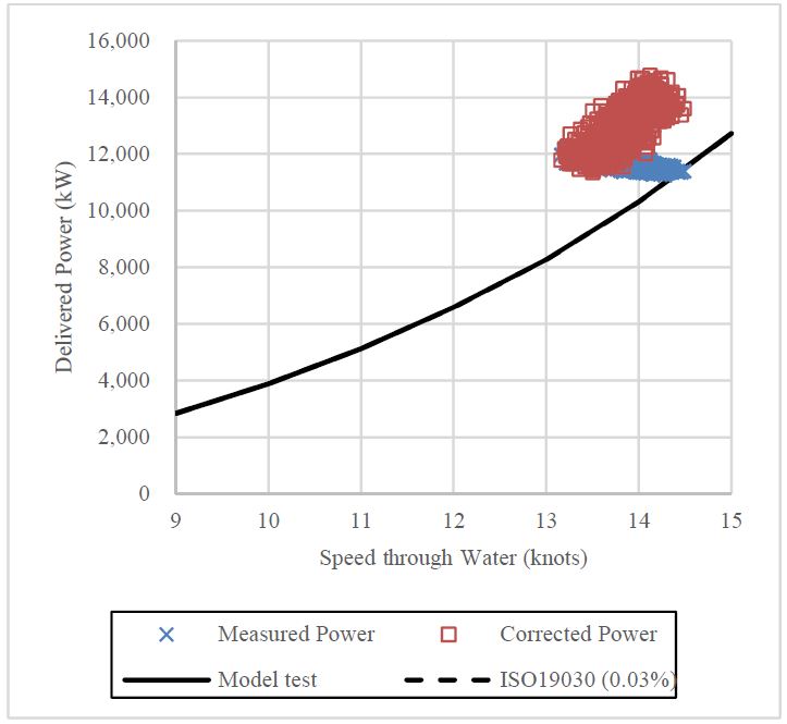
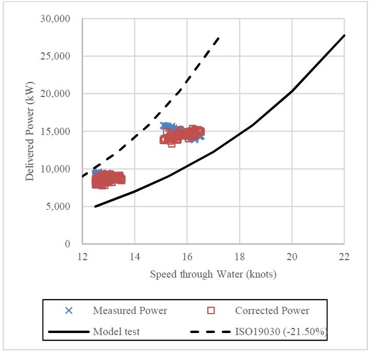
Figure 5 and Figure 6 show the analysis results of a 176K bulk carrier in ballast and laden loading conditions, respectively. The solid line in the charts represents the model test results. Since ISO19030 results are single values, which represent an averaged decrease in speed from the reference data that are usually the model test results, to make an intuitive visual representation of the results, a dashed line is drawn by shifting the model test curve along the direction of the speed (x) axis by the amount of the averaged Performance Value. In all analysis results, the measured power is corrected to form a line similar to the model test curve and the distance from the model test results to the corrected values, represented by red dots, are how much the performance of the ship has degraded from an as-new condition due to hull fouling, etc.
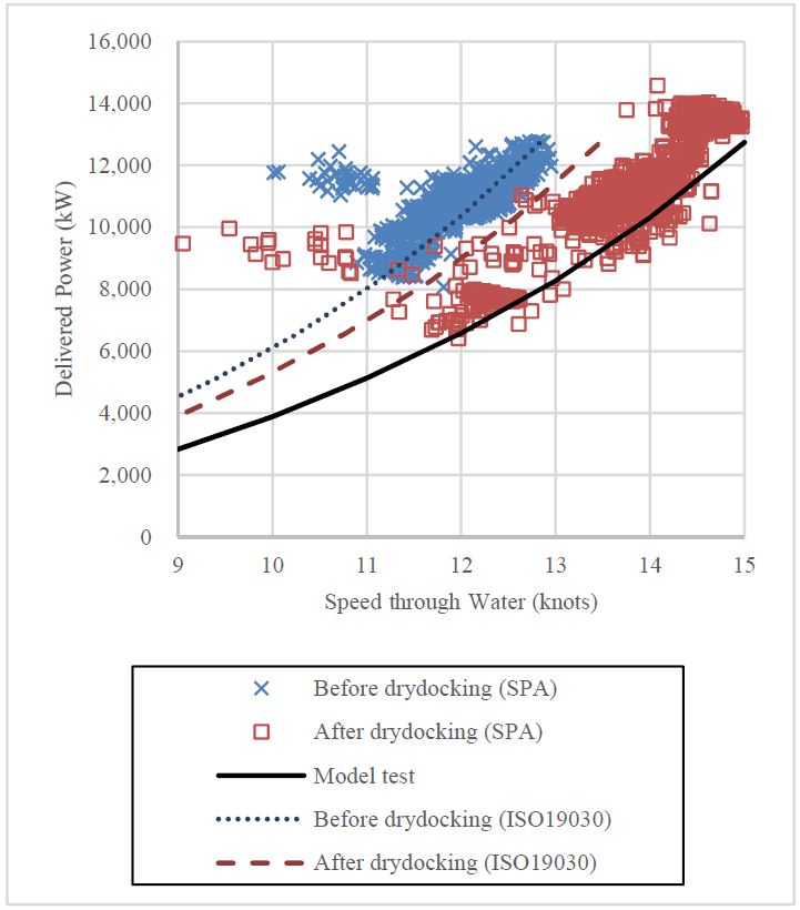
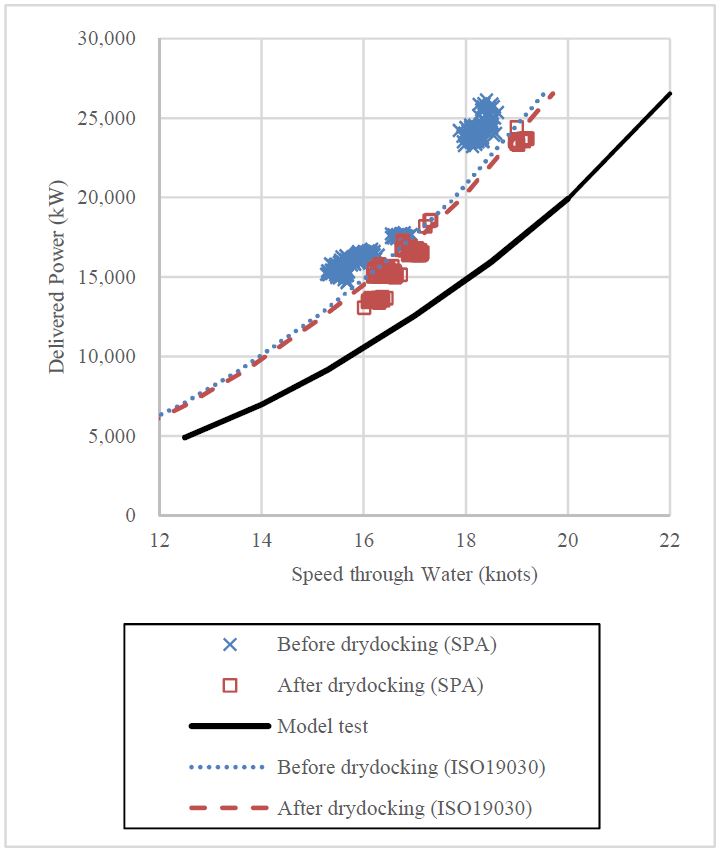
Figure 7 shows the difference in performance before and after dry-docking. The points represent the analysis results of the method proposed in this paper and the two types of dashed line represent the analysis results using ISO19030. Since ISO19030 relies on averaging out uncorrected environmental effects, at least three months of data is required. Therefore, only the method proposed in this paper can accurately show difference in performance before and after dry-docking with only one leg of a journey before and after. It is clearly shown in Figure 6 and Figure 7 where the performance analysis results of the method proposed in this paper significantly differ from those of ISO19030. Please note that ISO19030 analysis results in Figure 6 are not missing but overlap the model test results.
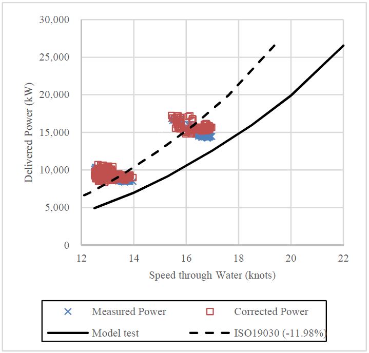
Figure 8 and Figure 9 shows similar results for the cases of an 8600TEU containers with 80% and 90% displacement conditions. In Figure 8, the analysis results using the proposed method and the results using ISO19030 are similar, however this is not the case in Figure 9. Thus, there is no guarantee that the proposed method will always give accurate and better analysis results than ISO19030. However the proposed results are more consistent and realistic than ISO19030, where the performance in some cases being only 0.03% different from the model test results (for the 176K bulk carrier laden condition results) or as low as -20% in speed in comparison with the model test results (for the 8600TEU container carrier 90% loading condition results).
Figure 10 shows the dry-docking effects of an 8600TEU container carrier, and the proposed method shows more realistic results than ISO19030, which shows dry-docking has almost no effects.
5. Conclusions
In this study, a new speed power analysis method based on ISO15016:2015 was proposed. The proposed method first evaluated the added or decreased resistance due to the environmental changes including wind, waves, and water density. Then, the measured shaft power was corrected using the direct power method, and finally, corrected to reference displacement for comparison. The proposed method was implemented in the SPA software, and applied to a 176K bulk carrier and an 8600TEU container carrier. The results show that the proposed method has the following advantages:
- ① Offers more information than just a value (averaged Performance Value) as in ISO19030.
- ② Able to provide a more realistic representation of performance than ISO19030, with only a small amount of data, typically with one leg of a journey.
- ③ Only uses data already collected by ship operators, so that no new data measurements are necessary.
The proposed method and the SPA software that was implemented in this study can be applied to estimate the powering performance of the operating ships used to verify the effects of energy saving devices and low friction paint, which will help decrease fuel consumption and reduce greenhouse gas emissions.
Acknowledgments
This research was sponsored by the Ministry of Trade, Industry & Energy (Korea Government) under the project “Development of advanced speed-power analysis technology to attain high energy efficiency and GHG reduction of operating ships under real sea condition (PNS3190)” and “Accuracy enhancement of model-ship correlation based on the ship performance measurement (PNS3370)”.
Author Contributions
Conceptualization, B. J. Park and M. S. Shin; Methodology, B. J. Park, M. S. Shin, and G. J. Lee; Software, B. J. Park and G. J. Lee; Formal Analysis, B. J. Park, M. S. Shin, G. J. Lee, and M. S. Ki; Resources, B. J. Park and M. S. Shin; Data Curation, M. S. Ki; Writing—Original Draft Preparation, B. J. Park; Writing—Review & Editing, B. J. Park; Visualization, B. J. Park; Supervision, M. S. Shin and G. J. Lee; Project Administration, M. S. Shin and M. S. Ki; Funding Acquisition, M. S. Shin;
References
- ISO, “ISO19030 ships and marine technology – Measurements of changes in hull and propeller performance,” ISO, Geneva, 2016.
- H. Goler and K. Bozkurt, “Speed loss analysis of high-speed Ro-Ro vessels coated with new antifoulıng technologies,” HullPIC 2017 (2nd Hull Performance & Insight Conference), Ulrichshusen, Germany, 27-29 March, 2017.
- B. Kidd, H. Chen, Y. Seah, W. X. Chue, and A. A. Finnie, “Practical experience with ISO 19030 at chevron shipping - part 2,” HullPIC 2018 (3rd Hull Performance & Insight Conference), Redworth, UK, 12-14 March, 2018.
- D. Schmode, O. Hympendahl, and D. Gundermann, “Hull performance prediction beyond ISO19030,” HullPIC 2018 (3rd Hull Performance & Insight Conference), Redworth, UK, 12-14 March, 2018.
- V. Tsarsitalidis and S. Rossopoulos, “ISO 19030 -The good, the bad and the ugly,” HullPIC 2018 (3rd Hull Performance & Insight Conference), Redworth, UK, 12-14 March, 2018.
- J. Park, B. Kim, H. Shim, K. Ahn, J. H. Park, D. Jeong, and S. Jeong, “Hull and propeller fouling decomposition and its prediction based on machine learning approach,” HullPIC 2018 (3rd Hull Performance & Insight Conference), Redworth, UK, 12-14 March, 2018.
- D. Gundermann and D. McLaughlin, “When ISO19030 fails: Utilizing basic machine learning/data fitting methods for performance analysis without reference data,” HullPIC 2019 (4th Hull Performance & Insight Conference), Gubio, Italy, 6-8 May, 2019.
- M. Jeon, Y. Noh, K. H. Jeo, S. B. Lee and I. Lee, “Real ship maritime big data analysis for prediction of fuel consumption,” HullPIC 2019 (4th Hull Performance & Insight Conference), Gubio, Italy, 6-8 May, 2019.
- ISO, “ISO15016 ships and marine technology – Guidelines for the assessment of speed and power performance by analysis of speed trial data,” ISO, Geneva, 2015.
- M. S. Shin, B. J. Park, G. J. Lee, and M. S. Ki, “Revision of the ISO15016 and analysis program (i-STAP) for the analysis of the standard EEDI speed,” Bulletin of the Naval Architects of Korea, vol. 53, no.1, March, 2016 (in Korean).
- B. J. Park, M. S. Shin, M. S. Ki, G. J. Lee, and S. B. Lee, “Experience in applying ISO19030 to field data,” HullPIC 2017 (2nd Hull Performance & Insight Conference), Ulrichshusen, Germany, 27-29 March, 2017.
- B. J. Park, M. S. Shin, M. S. Ki, G. J. Lee, and S. B. Lee, “Ideas on how to improve ISO19030 based on the results of applying to field data,” HullPIC 2018 (3rd Hull Performance & Insight Conference), Redworth, UK, 12-14 March, 2018.

