Experimental approach of tow behaviors in resin-impregnated glass fiber for GFRP manufacture
Copyright © The Korean Society of Marine Engineering
This is an Open Access article distributed under the terms of the Creative Commons Attribution Non-Commercial License (http://creativecommons.org/licenses/by-nc/3.0), which permits unrestricted non-commercial use, distribution, and reproduction in any medium, provided the original work is properly cited.
Abstract
Over the last decade, the demand for glass fiber and carbon fiber reinforced composites has been increasing in composite industries, such as aerospace, wind energy, automotive, and marine industries. This study focuses on composite-material based turbine blade manufacturing, especially for the glass fiber behavior in resin flow, which can be observed in the process of resin impregnation in fibers with different flow rate conditions. Tow deformation was observed for the two main tow behaviors—tow thickness and distance. The results confirmed that tow thickness decreased when positioned along the flow direction with increasing flow rate. Furthermore, the distance between the tows also decreased when positioned along the flow direction.
Keywords:
Wind turbine blade manufacturing, Glass fiber reinforced polymer (GFRP), Tow deformation1. Introduction
The consideration of environmental effects enables us to convert conventional energy sources and fossil fuels, such as petroleum and carbon energy, to environmentally friendly energy sources, such as solar, wind, hydro, and geothermal resources [1]. All of the latter energy forms are regarded as green, clean, and renewable, which aim to address the shortage in commodities and increasing energy demands. The rising consumption of fossil fuels is expected to the increase in greenhouse gas emissions and global temperatures, resulting in potentially catastrophic and irreversible climate change [2]. Therefore, seeking to adopt alternative energy sources can help to reduce CO2 emissions [3].
Meanwhile, over the last decade, the annual demand for glass fiber and carbon fiber reinforced composites has been increasing in composite industries. Specifically, the demands for carbon fiber reinforced composite materials are expected to reach 150 kton/year by 2020 [4][5]. Similarly, composites have been widely used across industries, such as the aerospace, wind energy, automotive, and marine industries. With these trends, there has been a need for a robust manufacturing process using advanced glass fiber reinforced polymer (GFRP) and carbon fiber reinforced polymer (CFRP) to obtain high quality composite materials. Various industries utilizing composite materials have been increasing rapidly with the increase in the demand for composite production parts. Among them, wind energy has developed rapidly throughout the world with increasing energy consumption, decreasing pollutants, and the increasing demand for environmentally friendly energy sources. The European Commission aims to reach the target of providing a high percentage of the overall primary energy consumption and approximately one-quarter of electricity by renewable energy sources in the EU [6].
One of the most adaptable renewable energy is wind power (wind turbine). A wind turbine utilizes wind energy by facing the turbine in the wind direction and converts the resulting mechanical rotation into electric power. The wind turbine components comprise a foundation, tower, wind orientation control, generator, rotor blade, etc. A robust design of wind turbine blades is crucial because the blades directly affect the efficiency of power produced.
This study focuses on turbine blade manufacturing using composite materials. The primary focus of this manufacturing is the process of resin ingress in glass fiber. In the turbine blade manufacturing, the glass fiber reinforcement was impregnated, and the shells were adhesively bonded together to the spars. This technology was used mainly to produce medium-sized blades (up to 35 and 55 m, respectively). For larger blades, the same technology was used, but the web was inserted and adhesively bonded between two sides and the plies using more fiber [7]. One of the common problems in blade manufacturing is resin impregnation in fibers. In the process of resin impregnation, investigation of tow behavior is crucial for the robust design of blade manufacturing of turbines. Therefore, tow behavior in glass fiber is investigated primarily in wind turbine blade manufacturing as part of the GFRP manufacturing.
Here, the glass fiber behavior in resin flow is primarily observed in the process of resin impregnation in fibers under different flow rate conditions.
2. Characteristics of Wind Turbine Blades Manufacturing
2.1 Rotor diameter of turbine blade
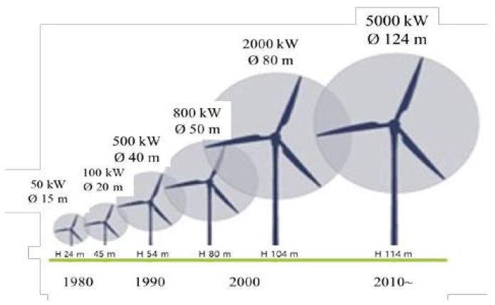
In the 1980s, during the initial period of wind power manufacturing, small 100–150 kW turbines were constructed. With the increasing growth of the industry throughout the onshore and offshore areas, 2–5 MW capacities of large wind power facilities have been constructed, as depicted in Figure 1 [8]. Lightweight material for the wind turbine blade is attributed to the integration of fiber-reinforced plastics (FRPs). These are efficient in demanding applications that require a high aspect ratio (length to width ratio). FRPs are commonly used in wind blades to increase their strength. With the increasing demand for a high aspect ratio and lightweight turbine blades, the primary goal of the manufacturing technology is to adopt the FRP process [8].
2.2 The process of GFRP for turbine blade manufacturing
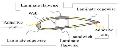
The composition of the wind turbine blade section is illustrated in Figure 2 and the materials required for the various wind turbine sizes are summarized in Table 1. Glass fiber reinforcement is chiefly adopted for manufacturing wind turbine blade. The glass fiber reinforcement is impregnated using paintbrushes and rollers. This technology is mainly used to produce small and medium-size blades (up to 35 and 55 m, respectively). The widely used method for manufacturing wind turbine blade is vacuum infusion, while prepreg technologies are used to improve the quality of the turbine blade.

Summary of various Megawatt wind turbines with defining characteristics and blade material choices [12]-[15]
The same technology is used for the longer blade; however, the web is inserted and adhesively bonded between two sides. Furthermore, plies with more fiber content are used. The most widely used technology to produce the wind blades is the resin infusion technology. This technology can be categorized into two groups: Resin Transfer Molding (RTM) and Vacuum Assisted Resin Transfer Molding (VARTM) [9]. Currently, VARTM is the most common manufacturing method for manufacturing wind turbine rotor blades. With various technologies, the primary issue is the resin impregnation in fiber tow. Therefore, investigation of tow behavior in resin flow is an important aspect in the manufacture of wind turbine blades [10].
3. Experimental conditions
3.1 Materials and apparatus
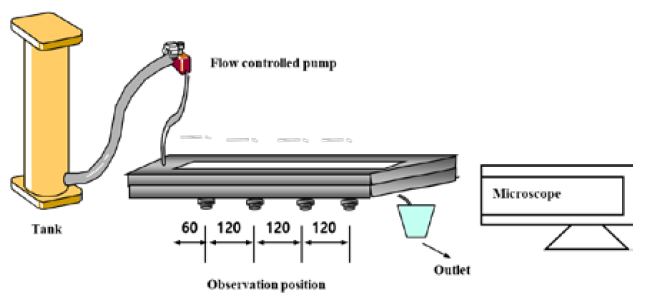
This study investigated the flow in a fiber medium when a fluid with constant flow rate was injected into an experimental test apparatus, as depicted in Figure 3. Non-crimped unidirectional fiber mat (3 K plain carbon fabric, Ownes Corning) was used as the base for the manufacture of the turbine blade. Characteristics of the fiber are presented in Table 2. One tow bundle was made of approximately 2000 single fibers. The width and thickness of the bundle were 2 mm and 0.43 mm, respectively. A knit yarn was used for maintaining the structure of the reinforcement that is made out of polyester. The knitting yarn weight was 1.3% of the total weight. Therefore, it does not affect the resin fluid flow.
The fluid used in this experiment was silicone oil (KF-96, Shin Etsu) because of its high chemical stability. Its fluid properties are listed in Table 3. Glass fibers were placed on the lower mold along the flow direction and the fluid was introduced into the mold cavity. The fluid was injected from a resin injection pump. The fluid was injected at two distinct constant flow rates by the pump. A uniform length of fiber (100 mm) was cut from a UD glass roving fiber with a cutter. The UD glass fiber was put into the mold, and the mold cavity was clamped with a hydraulic press enabled to maintain a constant closure condition. The fiber behavior was observed with a microscope.
3.2 Experimental conditions
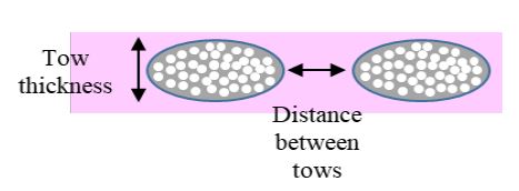
Tow behavior was observed to determine the effect of hydrodynamic pressure and fluid flow propagation. To observe the effect of hydrodynamic pressure, two different injection conditions were maintained at 50 mm3/s and 200 mm3/s. To observe the effect of fluid flow propagation, tow behavior in glass fiber was observed at four points along the fluid direction, 60, 180, 300, 420 mm, respectively, from the inlet and tow deformation with main tow behaviors as observed in Figure 4.
3.3 Image production
Various samples of the UD glass fiber were observed from the specimens cut through the glass fiber tow centerline along the flow direction. The specimens were examined under a video microscope. The entire unit cell was imaged in one low-resolution image during our initial attempts. Image splicing technique was adopted to obtain high-quality images to measure the tow geometry data with a reasonable accuracy, where a number of high-resolution images were obtained by covering a part of the weave unit cell for every image.
4. Experimental results
4.1 Observation of tow deformation
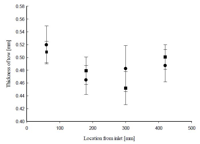
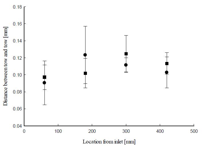
Tow behaviors with respect to flow rate were investigated. Tow deformation was observed for the two primary tow behaviors: tow thickness and distance between tows with respect to the effects of hydrodynamic pressure and fluid flow propagation, as shown in Figure 5 and Figure 6.
The results of the tow thickness behavior with respect to flow rate observed in Figure 5 indicated that the thickness decreased when the tow was positioned along the flow direction. Further, the thickness further decreased with a larger flow rate. This is due to the hydrodynamic force exerted by the fluid flow, which results in tow deformation. The hydrodynamic force compressed the tow along the flow direction. As the fluid was introduced near the inlet, the void in the fluid moved along the flow direction in the flow developing region. In the flow developed region (at the near 180 mm), most of the void moved past the tow to the outlet. In this case of the developed region, a hydrodynamic force was exerted to the tow with a relatively small void. Therefore, compressed behavior increased rapidly. After that point, pressure drop increased along the flow direction. Compressed relaxation behavior is when the compressed tows retain their original shape with decreased hydrodynamic fluid force. The thickness of tow then increased along the flow direction with decreased hydrodynamic force due to the pressure drop.
The distance between tows with respect to flow rate was investigated and the result was shown in Figure 6. The tow compressed due to the hydrodynamic force and the distance between the tows decreased when positioned along the flow direction.
With a small flow rate (50 mm3/s), a large variation in distance between tows was observed when compared with that of the large flow rate (200 mm3/s). For the 50 mm3/s flow rate tow compression was observed in the flow range location of 420 mm. In the flow developing and developed region, different tow thickness was observed with different compressed behavior with different hydrodynamic force. Increasing compressed and compressed relaxation of tow resulted in different distances between tows.
Generally, as the tow compressed, it was expected that the thickness of the tow would decrease. The experimental results were in sync with the expected results. However, a delay in response of the behavior of the distance between the tows was observed. At a flow rate of 50 mm3/s, a compressed tow indicating decreased tow thickness was observed with increasing distance between the tows (in the position of 180 mm). The expected decrease in the distance between the tows was observed after the 300 mm position. This tendency was more dominant at the flow rate of 200 mm3/s.
5. Conclusion
Tow deformation was observed for the two main tow behaviors—tow thickness and distance between tows in the flow rate range (50–200 mm3/s). The results confirmed that the thickness of the tow decreased when positioned along the flow direction with increasing flow rate. This decrease was due to the hydrodynamic force exerted by the fluid flow, resulting in tow deformation. Furthermore, the distance between the tows decreased when the tows were positioned along the flow direction. This is due to the increase in compressed relaxation of the tow showing a delayed response in the distance between the tows at a flow rate of 200 mm3/s.
Acknowledgments
This work was supported by the Korea Institute of Energy Technology Evaluation and Planning (KETEP) and the Ministry of Trade, Industry &Energy (MOTIE) of the Republic of Korea (No.20173010024970).
Author Contributions
Conceptualization, S. W. Choi and H. M. Yoo; Methodology, J. S. Kwon; Validation, J. H. Yang; Formal Analysis, H. S. Ryoo; Investigation, J. S. Kwon; Data Curation, J. H. Yang; Writing—Original Draft Preparation, H. S. Ryoo; Writing—Review & Editing, S. W. Choi and H. M. Yoo; Visualization, J. S. Kwon and J. H. Yang; Funding Acquisition, H. S. Ryoo;
References
-
O. Ellabban, H. Abu-Rub, and F. Blaabjerg, “Renewable energy resources: Current status, future prospects and their enabling technology,” Renewable and Sustainable Energy Reviews, vol. 39, pp. 748-764, 2014.
[https://doi.org/10.1016/j.rser.2014.07.113]

-
K. Menyah and Y. Wolde-Rufael, “CO2 emissions, nuclear energy, renewable energy and economic growth in the US,” vol. 38, no. 6, pp. 2911-2915, 2010.
[https://doi.org/10.1016/j.enpol.2010.01.024]

- Renewable Energy Embraces Graphene: Improved Wind Turbine Technology, http://www.azocleantech.com/article.aspx?ArticleID=455, , Accessed November 19, 2019.
- Toray’s Business Strategy for Carbon Fiber Composite Materials, http://www.toraycfa.com, Accessed November 19, 2019.
-
M. F. Akorede, H. Hizam, and E. Pouresmaeil, “Distributed energy resources and benefits to the environment,” Renewable and sustainable energy reviews, vol. 14, no. 2, pp. 724-734, 2010.
[https://doi.org/10.1016/j.rser.2009.10.025]

-
K. Kalkanis, C. S. Psomopoulos, S. Kaminaris, G. Ioannidis, and P. Pachos, “Wind turbine blade composite materials-End of life treatment methods,” Energy Procedia, vol. 157, pp. 1136-1143, 2019.
[https://doi.org/10.1016/j.egypro.2018.11.281]

-
L. A. Merugula, V. Khanna, and B. R. Bakshi, “Comparative life cycle assessment: Reinforcing wind turbine blades with carbon nanofibers,” Proceedings of the 2010 IEEE International Symposium on Sustainable Systems and Technology, pp. 1-6, 2010.
[https://doi.org/10.1109/ISSST.2010.5507724]

- Expoxy Resins–Polymers and Polymer Composites, https://www.cranfield.ac.uk/people/dr-sameer-rahatekar-15445392, , Accessed November 19, 2019.
-
D. A. Griffin and D. A. Thomas, “Alternative composite materials for megawatt-scale wind turbine blades: design considerations and recommended testing,” Journal of Solar Energy Engineering, vol. 125, no. 4, pp. 515-521, 2003.
[https://doi.org/10.1115/1.1629750]

- S. W. Beckwith, “Resin infusion technology—Part 3: A detailed overview of RTM and VIP infusion processing technologies,” SAMPE Journal, vol. 43, no. 4, 2007.
-
L. Mishnaevsky, K. Branner, H. N. Petersen, J. Beauson, M. McGugan, and B. F. Sørensen, “Materials for wind turbine blades: an overview,” Materials, vol. 10, no. 11, 2017.
[https://doi.org/10.3390/ma10111285]

- Vestas Wind Systems A/S, https://www.vestas.com/en/media/brochures.aspx, , Accessed November 19, 2019.
- Enercon GmbH. Enercon. https://www.enercon.de/en-en/66.htm, , Accessed November 19, 2019.
- Siemens Energy. https://www.energy.siemens.com/us/en/power-generation/renewables/wind-power/wind-turbines/swt-3-6-120.htm#content=Technical%20Specification, , Accessed November 19, 2019.
- Suzlon – Power a Greener Tomorrow. https://www.suzlon.com/products/l2.aspx?l1=2&l2=9, , Accessed November 19, 2019.

