Recent advances in natural gas hydrate carriers for gas transportation - A review and conceptual design
Natural gas hydrate (NGH) is emerging as a new eco-friendly source of energy to replace fossil fuels in the 21st century. It is well known that the Natural Gas Hydrate contains large amount of natural gas about 170 times as much as its volume and it is easy to be stored and transported safely at about –20℃ under atmospheric pressure due to so called “self-preservation effect”. The option of gas transport by gas hydrate pellets carrier has been investigated and developed in various industry and academy. The natural gas hydrate pellet carrier is on major link in a potential gas hydrate process chain, starting with the extraction of natural gas from the reservoir, followed by the production of hydrate pellets and the transportation to an onshore terminal for further processing or marketing.
In recent years, Korean project team supported by Korean Government has been working on the development of NGH total systems including novel NGH carrier since 2011. In order to increase the knowledge on the NGH pellet carrier developed and to understand the major hazards that could have significant impact on the safety of the vessel, this paper presents and evaluates the pros and cons of cargo holds, loading and unloading systems through the analysis of current patent technology. Based on the proven and well-known technologies as well as potential measures to mitigate sintering and minimize mechanical stress on the hydrate pellet in the self-preservation state, this study presents the conceptual and basic design for NGH carrier.
Keywords:
Natural Gas Hydrate, Gas Carrier, Pellet, Liquified Natural Gas, Loading/Unloading1. Introduction
With the steep rise in oil prices recently, shipping industry is increasingly looking for alternative fuel sources to operate its ships. The natural gas hydrate is regarded as the new eco-friendly energy resources to replace the fossil fuel. The NGH (Natural Gas Hydrate) has relatively low ship building costs compared to transporting the natural gas in the way of liquefying by cooling to -162 ℃. For such a reason, the NGHC has the advantage of being able to operate in small and medium-sized gas fields which are economically infeasible (Gudmundsson et al. [1], Kanda [2], Nogami et al. [3]). With regard to the economic feasibility of the gas hydrate approach for transporting natural gas from offshore reservoirs, the above mentioned studies commonly indicate that the hydrate technology has advantages over established technologies such as pipeline or liquefied natural gas (LNG) transportation or compressed natural gas (CNG) transportation, especially under the boundary conditions of small production capacities and small to medium transportation distances.
Mitsui Engineering & Shipbuilding Co., Ltd. (MES) has been continuously investigating the comprehensive NGH technology development to complete the gas transportation chain, such as NGH formation, dewatering, pelletizing, storage, sea transportation, loading/unloading system since 2001. In particular the NGH “pellet” system is superior in many points including high filling ratio in ship cargo tanks, good fluidity and enhanced self-preservation effect, and that is one of the best solutions to make NGH sea transportation more feasible (Ota et al. [4], Nakajima et al, [5]). The NGH pellet carrier is one major link in a potential gas hydrate process chain, starting with the extraction of natural gas from the reservoir, followed by the production of hydrate pellets and the transportation to an onshore terminal for further processing or marketing.
In 2008, the joint project “SUGAR” has been initiated in Germany to develop new technologies for the exploration and exploitation of submarine gas hydrate resources as well as concepts for the transport of gas, respectively, natural gas from hydrate reservoirs (SUGAR [7]). In their results, the potential of a gas hydrate transport chain has been re-investigated by a consortium of partners in total 30 partners from industry and scientific community. Furthermore, for the first time, an extensive assessment of the risk associated with the ship transport of natural gas hydrate pellets has been carried out.
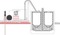
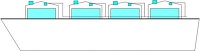
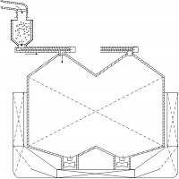
Figures 1 and 2 show the conceptual designs of the pellet carrier by MES and Germanischer Lloyd (Rehder et al. [6]), respectively.

Conceptual design of natural gas hydrate pellet carrier by MES(2001-2003)

Conceptual design of methane hydrate pellet carrier by Germanischer Lloyd (Rehder et al. [6])
NGH transport by ships is in development phase that has not been built and the international regulation has not been established in this regard. In the late 2000s, Japan proposed the development of safety requirements on the NGH transports to the International Maritime Organization (IMO). And Japan submitted the guideline on the NGH transports based on IGC Code in 2009, but due to the fact that natural gas transportation via methane hydrate pellets represents an innovative approach, no final codes for gas hydrate carriers are existent yet.
However, the systems which were suggested by Japan were mostly the way that unloaded the hydrate as solid-state (pellet) in the cargo hold. In the case of the hydrate pellets, they should be separated by mechanical force, because they could be matted under steady pressure. Moreover, the systems need to build the storage tank on the land to store the hydrate which is unloaded from the NGH transport vessel. For the transport to the storage tank, it has to install the long conveyor belt which has the equipment for preventing to leak the gas after the dissociation.
Meanwhile Korea research team, in recent years, is stepping up with development of technology for NGH transport under support of the government to develop the cargo storage tank, loading and unloading system, an assessment of the risk associated with the NGH carrier.
This paper deals with strength and weakness of each patent technology reported till now. Based on the overall previous results and appropriate application scenarios, also, it presents the direction of conceptual design of NGH transports of which this technical development tries to carry forward.
2. Evaluation of loading and unloading system
2.1 Loading system
Loading system can be divided into a solid type and slurry type depending on state of NGH cargo. As given in Table 1, the loading system as a gas state is fundamentally impossible because the NGH is a solid cargo. Also, the solid particle-type loading system can be divided into four types depending on transferring means of NGH for shipping: conveyor belt/screw type, high-pressure gas type, container type and direct-loading type.

Classification of loading and unloading system depending on state of NGH
Of all these loading system, all the types except for the direct-loading system have additional devices to set up the NGH carrier. As a result, the costs of ship building rise, the reliability and the transport efficiency for loading system go down because of inefficiency design of cargo hold. Due to previous stated problems, the direct loading system was analyzed as the most efficient type. This system has a similar function as a conventional bulk carrier and load NGH cargo directly from the upper cargo hold by using loading facilities. The loading facilities must be designed in closed type because flammable natural gas is continuously dissociated from NGH during loading.
And the loading system can be classified in detail again depending on kinds of NGH transporting as shown in Table 2.
Classification of loading systems depending on transporting method of NGH
2.2 Unloading system
Unloading system can be divided into solid, slurry and gas type depending on state of NGH as presented in Table 3. Solid- transferring type which is similar to above stated in section 2.1 can be sub-divided into conveyor belt/screw type, high-pressure gas type, container type and direct-unloading type after crushing. All the types except for the gas-unloading type and the direct-unloading type after crushing may be difficult to commercialize because they have a similar problem which described in the loading system. Hence, the transferring systems of the gas-unloading and direct-unloading type which can be simplified the most and a highly reliable were analyzed in the most efficient system for NGH pellet carrier.
Classification of unloading system depending on transporting type of NGH
The gas-unloading type is a mode of supplying only natural gas to end-user of land after dissociating NGH on vessels. At this time, the equipment such as pumps, heat exchangers and compressors for dissociation, compression and transferring of NGH are installed on land and when necessary, they may be used in connection with NGH carriers. However, the NGH carriers should be anchored at unloading dock for a certain period of time until all the loaded NGH cargo transported to the land gas-storage facility after dissociation.
2.3 Classification of loading/unloading system depending on transferring mode
The systems which are suggested by Japan are mostly the way that loaded and unloaded the hydrate as solid-state in the cargo hold. Most of the solid cargos such as hydrate are transported by conveyor belt or screw equipment. In case of the hydrate pellet, they should be separated by force, because they could be matted under steady pressure on it.
In addition, the systems need to build the storage tanks on the land for storing the hydrate which is unloaded from a NGH carrier. For the transferring to the storage tank, they have to install a long conveyor belt which has the equipment for preventing to leak the gas after the dissociating. Due to these factors, the transportation cost to the land and the storage facilities are significantly increased.
Table 4 shows the patent related to solid parparticle-type loading/unloading systems, and many of them have been applied in Japan. However, if we look into the patents related to loading/unloading systems, most of patents as solid-state has the merits, but it has too many limitation being a reality because they have many problems at present state of the technology.
Patented technologies related with solid loading and unloading system
This system is able to load and unload the hydrate pellet in slurry through pipelines. But this system makes fall of transferring efficiency because of transporting with slurry solution compared to the transferring system of hydrate only as presented in Table 5. This system is fundamentally impossible because it cannot discharge hydrates from the bottom of cargo hold in which hydrates could be matted under steady pressure. To apply this system, additional devices should be installed at the bottom of cargo hold to pull out the hydrate.
Patents related with slurry-type loading/unloading system
If hydrate gets heat, it separates the gas molecule from the water molecule and generates water and natural gas. Using this principle, the system can supply only natural gas to the land by supplying heat into the inside of cargo hold as shown in Table 6.
Patents related with gas loading/unloading system
In this case, additional devices are needed for supplying heat to the NGH carrier but they have advantage of reducing construction costs because large conveyor belt and storage tank for transferring hydrates to land are not necessary and only need to install gas transferring pipeline.
However, if the NGH vessel transports large quantities of hydrates, it could be inefficient because the carrier must be anchored from more than one week to for weeks at the unloading dock for gas dissociation.
2.4 Patented Technologies depending on loading/unloading system
Patented technologies mentioned above are classified with loading systems as presented in Table 7. Looking at the mentioned classification, we can see that the patent, falling type from outside to the top of cargo hold, is not so far investigated to apply. However, similar systems are expected to exist or prepare because most of bulk carriers which are similar in hydrate carriers will load or unload directly by using external loading and unloading devices in the future.
Patents related with transferring system in loading
Table 8 is classified with the mode of unloading system with solid particle. The direct unloading system like direct loading system is not investigated to apply related patent. As can be seen from the Table 7 and 8, the system that load and unload directly in hydrate pellet type was not investigated. However, compared to the LNG carrier, the system could be the most simple and effi cient system in terms of hydrate carrier in which it has less constraints and used in bulk carriers during loading/unloading. For such a reason, this study propose a direction of conceptual design for direct-type loading/unloading system.
Patents related with transferring system in unloading
3. Conceptual design of loading system for NGH pellet carrier
3.1 Selection of loading system
In Table 9, all types of design are examined and compared by considering stability in systems, installation costs, operation costs and maintenances costs, etc. As the result of examination about all possible loading system, it is identified that the most effective way is the direct-type loading system.
Comparison of pros and cons for loading system in NGH carrier
3.2 The concept of direct-type loading system
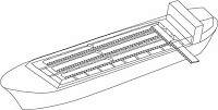
The system is loaded the hydrate by dropping directly from the upper part of cargo hold to the bottom by putting transfer device for loading hydrate into the entrance, where located at the upper part of carrier’s cargo hold. This system need not to install additional device on the carrier due to loading the hydrate directly into the interior of carrier’s cargo hold by using loading/unloading facilities of wharf as shown in Figure 3. Therefore, the cost of installation and maintenance can be decreased.

Conceptual design of direct loading system
Due to the cone-shaped design of cargo hold in a cross section, this system maximize the loading capacity when hydrates are loaded into the cargo hold. At this time, the loading device and cargo hold must be sealed completely in which the outside air should not pass into the inside of cargo hold or loading device. Moreover, 2 ~ 3 loading devices must be installed at loading station to make loading as quickly as possible, and redundant loading device must be able to resume the loading work immediately when loading device made breakdown.
4. Conceptual design of unloading system for NGH carrier
4.1 Selection of unloading system
In Table 10, the unloading system depending on the transferring system was analyzed, and two type of loading system, that is, the direct-type unloading system after crushing and the forced transferring system after dissociation were compared with each other. Here, they were proven to be the most effective methods in terms of stability in systems, installation costs, operation costs and maintenances costs, etc.
However, it is hard to say how good these systems are because of the two systems have complementary advantages. So, we investigated the direction of conceptual design for both two systems. Here, we will only discuss the most feasible unloading system to solve the technical problem at the stage of basic design in current situation.
Analysis of pros and cons of unloading system
4.2 The concept of unloading system
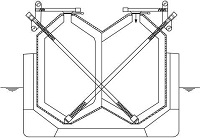
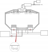
To pull out the loaded hydrate to outside of cargo tank or land, the hydrate lump must be smashed and taken out by bucket. However, a crusher is needed because it adhere to each other. If the bucket has enough strength and power to unload the matted hydrates after smashing, it would be possible to unload only for itself. Figure 4 shows the unloading concept using a crusher and bucket. This system has a passage at the inside of transfer tube that the bucket can move, and a crusher push the crushed hydrate towards the bucket. Unloading devices including a crusher and bucket must go through the gate of cargo tank to inflow inside of cargo tank. The gate of cargo tank performs a function not to leak natural gas outside when unloading devices insert or take out of cargo tank during unloading.

Conceptual design of pellet-type unloading system after crushing
When 1st shut-off gate-valve is open and the unloading devices move to 1st seal chamber, 1st seal chamber is supplied nitrogen for some time and filled with nitrogen (N2), then the chamber fundamentally cut off the possibility fire & explosion due to air ingress. And 2nd shut-off gate-valve is open, the unloading device goes into the cargo tank as shown in Figure 5. A number of sealing tube conducts a function to prevent the leakage of natural gas which generates in the cargo tank. Seal oil makes unloading devices and sealing tube well adhered and prevent the leakage of natural gas. Also, when the unloading device keeps going down, the sea oil makes well slid in unloading operation.

The up-and-down motion of bucket and crusher in seal chamber
The unloading device keeps going down, it crushes the matted NGH and transfers to outside of cargo tank. The device (unloading devices) has a one or more joints, and it can unload the NGH loaded in all section of cargo tank because of the rotational capacity itself.
All the NGH is unloaded inside of cargo tank in final loading step. After unloading is complete, the unloading device goes out in reverse order when it enters the gate of cargo tank. At this time, an air must not come into the cargo tank.
Forced transfer system after dissociation can be classified with water injection, heat coil and water circulation depending on a type of heat transfer to cargo tank. In this study, we reviewed above stated 3 systems, and selected the water circulation type after dissociation for unloading system.
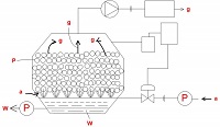
The water circulation system is the concept which continuously circulates fresh water for heating the cargo tank. And water storage tank is a tank to provide fresh water to the cargo tank in the initial heating process and not necessary to be placed in engine room. Fresh water injected to cargo tank is provided to the bottom of cargo tank as shown in Figure 6, contact with the NGH directly and dissociate the hydrate. Natural gas generated as the process is discharged to the upper part of cargo tank. At this time, fresh water of the cargo tank must be always circulated not to frozen and heated.

Conceptual design of the water circulation system
The circulation of fresh water in cargo tank is conducted by hot water circulating pump and the water goes through the buffer tank. The buffer tank performs a function not only to work well with the pump, but also to remove gas which might be existing in the fresh water.
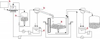
In order to supply a generated gas after dissociation to consumer (for example, power plant), blower or compressor is needed on the land. Figure 7 shows the concept of the forced transfer unloading system after dissociation using heating water from power plant. Fuel gas compressor can be added in order to use a natural gas generated from the cargo tank as a main or auxiliary power source.
Devices related to the loading system are roughly divided as follows.
- Cargo tank control system
- Dissociation gas unloading system
- Circulating water heating system
- Water discharge system
- Nitrogen (N2) purge system
- Fuel gas system for DF (Dual fuel) engine and boiler
- Gas detection system
- Propulsion

Schematic diagram of forced transfer unloading system after dissociation
5. Concluding Remarks
On the basis of fundamental knowledge about a gas hydrate carrier, a conceptual process design for loading and unloading system has been examined and developed through analyzing the current patented technologies. The design of the gas hydrate carrier, considering the current understanding for the properties of the cargo and foreseen mode of operation during loading and unloading, calls for a variety of new technological approaches.
In summary, the work presented in this communication has revealed that the most feasible loading/unloading systems to solve the technical problem at the stage of basic design in current situation are as follows.
1. Loading system : application of direct-type loading system
2. Unloading system : application of forced-type unloading system after dissociation
It should be mentioned, that the knowledge is needed to be enhanced and the process developments with a site-specific project are essential to verify respectively revise the results of the presented analysis.
Acknowledgments
This paper is extended and updated from the short version that appeared in the Proceedings of the International symposium on Marine Engineering and Technology (ISMT 2013), held at BEXCO, Busan, Korea on October 23-25, 2013.
References
- J. S. Gudmundsson, M. Mork, and O. F. Graff, “Hydrate non-pipeline technology”, Proceedings of the 4th International Conference on Gas Hydrate, p19-23, (2002).
- H. Kanda, “Economic study on natural gas transportation with natural gas hydrate (NGH) pellets”, Proceedings of the 23rd World Gas Conferences, p5-9, (2006).
- T. Nogami, N. Oya, H. Ishida, and H. Matsumoto, “Development of natural gas ocean transportation chain by means of natural gas hydrate (NGH)”, Proceedings of the 6th International Conference on Gas Hydrate, p6-10, (2008).
- S. Ota, H. Uetani, and H. Kawano, “Use of hydrate pellets for transportation of natural gas (III): Safety measures and conceptual design of natural gas hydrate pellet carrier”, Proceedings of the 4th International Conference on Gas Hydrate, p19-23, (2002).
- Y. Nakajima, T. Takaoki, K. Ohgaki, and S. Ota, “Use of hydrate pellets for transportation natural gas (II): Proposition of natural gas transportation in form of hydrate pellets,”, Proceedings of the 4th International Conference on Gas Hydrate, p19-23, (2002).
- G. Rehder, R. Eckl, M. Elfgen, A. Falenty, R. Hamann, N. Kahler, W. f. Kuhs, H. Osterkamp, and C. Windmeier, “Methane hydrate pellet transport using the self-preservation effect: A techno-economic analysis, energies”, 5, p2499-2523, (2012).
- SUGAR, http://www.ifm-geomar.de/ Accessed, 5), Nov, (2012.