Performance comparison of 10kW scale horizontal axis tidal turbines
Horizontal axis tidal turbines are machinery inherited from the principle of wind turbines to enable the application of utilizing ocean’s current energy. Its function does not differ from that of wind case, which is to convert fluid’s kinetics energy to mechanical torque, therefore generates electricity. Since the ocean has been an enormous source of untapped power, tidal turbines have been being investigated recently to meet human’s demand of energy with respect to environment friendly approach. This paper introduces a couple of turbine designs which are anticipated to have high performance. A comparison among recent works on the same topic is also made for validation.
Keywords:
Tidal turbine, Computational Fluid Dynamics, Tidal energy, Horizontal Axis TurbineNomenclature
A : Sweep area
CP: Power coefficient
r : Location along blade
R : Radius [m]
T : Torque [Nm]
V : Free stream velocity [m/s]
ρ : Fluid density [kg/m3]
ω : Rotational speed [rev/min]
λ : Tip speed ratio
1. Introduction
In this modern age, where renewable energy is being put in interest for the sake of global environment, ocean is a considerable resource that shows potential for developing such environmental friendly energy. Covering 70% of the earth surface, ocean is the largest solar collector that holds tremendous energies, a small portion of which would be able to cover the energy need of the entire world.
Tidal current is one type of water current that can be exploited for electricity. Tides are the rise and fall of sea levels caused by the combined effects of the rotation of the earth and the gravitational forces exerted by the moon and the sun. The tides occur at an interval of approximately 12 and half hours, so it is more predictable than wind, which highly depends on the weather. Currently, wind turbines with various sizes have become a familiar sight around the world. Their purpose is to collect energy from wind. Due to the cost reduction of installation and progressive government policies, wind power industry has become a key component of the power production industry in the world. A tidal turbine acts underwater in a very similar way to a wind turbine operates in the air. Instead of extracting energy from the air, a tidal turbine could collect kinetic energy from the water, which is thousand times denser than air, and so even slow moving tides can carry significantly larger energy than wind. Therefore, a tidal turbine has smaller diameter than a wind turbine of the same power output, resulting in lower cost of manufacture and transportation. Due to that, tidal turbine gradually attracts the interest of modern researchers and scientists for its potential. However, efficiency has been being a problem for this kind of machinery, which is not considered to be high. Maximum theoretical power coefficient is 0.593 according to Betz’s theory [1].
This paper brings about an analysis of tidal turbine’s performance using computational simulation. Two tidal turbine designs are introduced and predicted to have high performance. Of these two turbines, a compact design is proposed. The tidal device is 3-bladed horizontal axis turbine (HAT) and is rated at 10kW power output that is suitable for small application, designated to operate under the tidal current within 1-2m/s.
2. Turbine Design
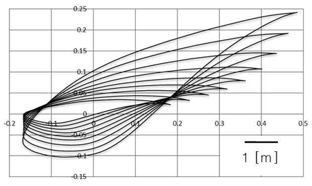
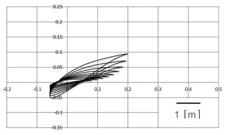
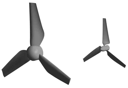
The major component of a turbine-like machine is the blade which directly affects the device’s performance. Basically, blade can be derived from hydrofoil profile by various methods. In this paper, blade elemental momentum theory (BEMT) is applied for the turbine design. Recently, several works put their interest on NREL S814 hydrofoil, i.e. the experiment of Barltrop et al. [2], or various works of Clarke et al. [3]. The major advantage of the S814 is its minimized sensitivity of maximum lift coefficient to roughness effects [4]. The S814 hydrofoil is also analyzed in this study for its popularity; full blade sections derived from this hydrofoil are illustrated in Figure 1. The figure shows shape and size of each hydrofoil section from blade root to the tip for 10kW scale tidal turbine. It is designed to operate at tip speed ratio (TSR) of 3 (rotational speed is about 20.4rpm); the modeling process results in rotor diameter of 4 meters in order for the turbine to operates efficiently. Additionally, another design of same power scale which is more compact is size, derived from Althaus’s AH-79-100B hydrofoil [5], is introduced in this paper. It is proved to have extremely high lift-to-drag ratio and much higher than that of the S814 (148.34 compared to 62.27 in this study). AH-79-100B HAT is only 2.4 meters in diameter, operates at the same TSR but has higher rotational speed (about 55.7rpm). The AH-79-100B blade hydrofoil sections are shown in Figure 2. Comparing Figure 1 and Figure 2, a significant difference in size between these two blades is clearly clarified.
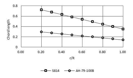
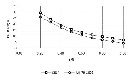
More detailed comparison is provided in Figure 3 and Figure 4. Completed rotor models of the two blades are shown in Figure 5. It is clearly seen that both S814 and AH-79-100B HATs have similar twist angle variation along the blade. Design parameters of both HATs are summarized in Table 1.
3. Numerical Method
Refering from various theories, aerodynamic researches and experiments, the turbo machinery like tidal turbine is either studied experimentally at varied scales or investigated computationally using methods that belong to the field of computational fluid dynamics (CFD). These two approaches are closely linked and have certain advantages as well as disadvantages. Experimental and computational research provide results for better understanding of the flow physics and enable investigation of energy exchange performance, a requirement in order to adjust the design of tidal turbines to the unique aerodynamic conditions in the environment. As with all methods of analysis, the CFD approach has limitations which are essentially related to turbulence modeling. But all in all, the cost of a CFD analysis that is highly comparable to that of an experiment. Comparison between CFD and experiment can be made for validation of the latter. Batten et al. performed an experimental study on a 3-blade horizontal tidal turbine in a cavitation tunnel and also in a towing tank [6], and the corresponding power and thrust coefficients were presented for a range of TSR. The experimental data provides very useful information for the design of tidal turbines and for the validation of numerical models. Several numerical methods were applied to analyze the performance of the same tidal turbine presented in the work of Bahaj et al. including blade element method [7][8]. Other numerical researches on HAT can be found, i.e. report of Lawson et al. at NREL [9] and panel method study of Baltazar et al. [10], which provide precise data to the numerical analysis of tidal turbine.
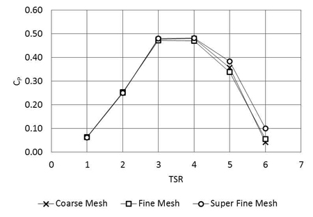
Based on built geometry, three dimensional model of blade and its flow-field are rendered in modeling commercial software, ICEM CFD. Hexa mesh is used for numerical discretization; it is structured mesh type that is convenient for meshing subjects with complex geometry like turbine blade. Mesh independency study was carried out. Figure 6 shows the sample from AH-79-100B calculation result, where three levels of mesh were examined including coarse mesh (about 2 million nodes), fine mesh (about 4 million nodes) and super fine mesh (up to 7 million nodes). Showing in Figure 6 are power coefficient (CP) versus TSR curves of AH-79-100B HAT at different mesh quality. According to this, there is no considerable difference between the three curves. Hence,the mesh size is limited up to 4 million nodes for both S814 and AH-79-100B in every simulations but guarantees to give accurate results.
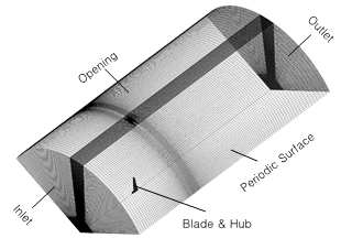
Normally, the turbine requires a cylindrical domain for CFD simulation. However, to reduce computational effort and because all three rotor blades are the same in all aspects, simulation is done on one-blade domain which is a one-third division of the full one (periodicity is 120o). The domain is set to rotating condition together with the blade and hub; its boundary conditions are indicated in Figure 7. Inlet boundary is normal speed, outlet boundary is static pressure, and opening boundary is set to “Opening Pressure and Direction”. The blades and hub are all no-slip wall boundaries. The rest of boundary conditions are the rotational periodic surfaces as shown in Figure 7. The fluid is sea water at 25oC, turbulence model is shear stress transport (SST) with turbulence intensity is set to 5% for the whole flow-field. All simulations are done in steady state by ANSYS CFX Solver.
In all simulation cases, both HATs are tested at TSR ranging from 1 to 6, corresponded to inflow tidal speed from high to low. The relationship between tidal free stream speed and blade’s rotational speed is described by TSR and given in following equation:
Hence, the input TSR and inflow tidal speed are set for six values as viewed in Table 2.
Turbine power efficiency is defined by power coefficient which is calculated from the output torque by the below equation:
4. Results and Discussions
4.1 Flow Patterns
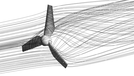
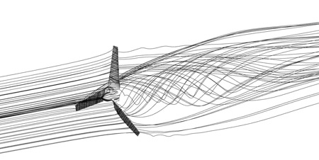
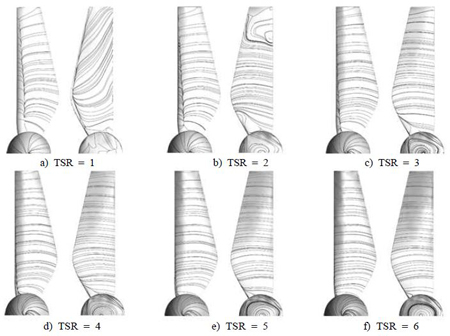
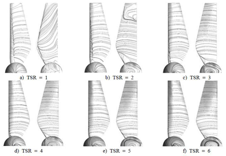
The two designed HATs both operate at TSR 3, Figure 8 and Figure 9. In turn show the visualizations of their wake and streamlines at rated TSR. The wakes of both HATs are similar with a clear appearance of big vortex region at the rear of rotor. The vortex is primarily formed at blade root, extends downstream and then ceases at the far wake region. No abnormal flow pattern is found at this operating point. Detailed flow patterns are illustrated thoroughly in Figure 10 and Figure 11. These figures show the blade surface streamlines of each HAT throughout the TSR range. In each sub-content of the figures, the pattern illustrated on the left is on blade’s pressure side, and the one on the right is its suction side.
For S814 blade (Figure 10), the patterns are well developed at all TSR except TSR 1 and 2, where there is the existent of radial flow and local turbulence.
Usually, fluid within turbine’s wake region should flow following the blade’s rotational movement. On blade’s pressure surface, the streamlines are distributed evenly and reasonably; in contrast, the stream lines on suction surface tends to move in radial direction from the root vortex toward tip (Figure 10a). Radial flow has no effect in transferring water’s kinetic energy into rotor’s torque due to the escape of water from the wake’s core region. The main reason for this is extremely high inflow tidal speed, the inflow speed up to around 5m/s is considered very high in terms of physical understanding. Thus, under such high speed flow, water is quickly detached from blades. At TSR 2 (Figure 10b), the radial flow effect ceases quickly but there is local turbulence of flow at tip region. At higher TSR (from 3 to 6), the streamlines are distributed evenly at both pressure and suction sides of the blade.
For AH-79-100B blade (Figure 11), the same phenomenon is found at TSR 1 and 2, where there is strong radial flow existent. The effect is much more considerable than that of S814 case but also disappears at TSR 3 (Figure 11c). At TSR 3 and 4, the blade has the steadiest and most laminar streamlines. However, the radial flow appears again and stronger at higher TSRs (Figure 11e and Figure 11f). At TSR 6, there is a tendency of local vortex formation. Those effects are unbeneficial for energy exchanging performance, thus power efficiency can be considerably influenced. But still, the patterns at operating TSR are agreeable.
4.2 Power output and efficiency
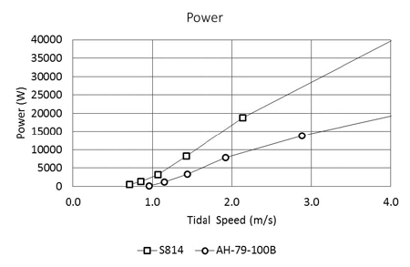
From the simulation results, power and efficiency data of all cases are extracted and input to graphs for comparison. Figure 12 presents the power output of the HATs under wide tidal speed range. Generally, the S814 HAT is able to produce more power than AH-79-100B HAT at the same tidal speed; the trend is more noticeable at high tidal speeds. Nonetheless, since the operating tidal range is 1-2m/s, both HATs are expected to meet the desired performance.
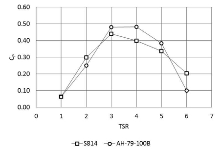
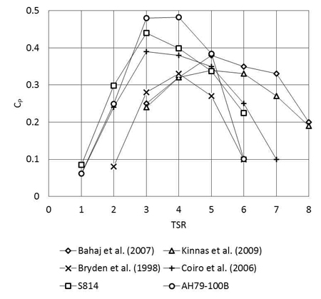
Figure 13 shows the efficiency curves (CP vs TSR) of the HATs introduced in this paper. From an overall perspective, AH-79-100B HAT has the highest efficiency, especially at operating TSR (CP is up to 0.48 at TSR3). This peak is maintained even at TSR 4 where CP is almost unchanged. The S814 has lower power efficiency but the variation of CP is less sloped than the AH-79-100B curve. Additional figure is provided to evaluate S814 and AH-79-100B HATs’performance among others’recent works (Figure 14). Figure 14 shows a series of performance curves of various researches and studies about tidal HAT. Among these, AH-79-100B HAT stays at the top for its most promising power efficiency; the second runner is the S814 HAT and followed by Coiro’s result [11]. The rest shows lower results where CP does not exceed 0.37. Kinnas [12] and Bahaj [7] have very similar curve characteristics; while Bryden’s pervious result [13] has the least performance. These results are varied by each author’s setup and conditions but provide useful information for reference and validation of S814 and AH-79-100B HATs’capabilities. In actual, most of the mentioned researches have experimental validated results, thus it is not a big inconsistency when numerical studies show higher performance; especially when various practical conditions and effects were not taken into account. Still, the results from S814 and AH-79-100B HATs are promising and prospective. Nevertheless, quantitative value of CP is only one aspect of tidal turbines; the compactness in size which is demonstrated in AH-79-100B design is a significant advantage and finding. However, high rotational speed in robust operational conditions demands additional studies for avoiding cavitations in rotor tip and reducing mechanical or electric losses.
5. Conclusions
This paper provides a numerical study on the performance of tidal turbines as a potential method of harnessing tidal current energy. The study not only introduces HATs that have high and comparative performance but also proposes a design that results in smaller size of turbine for the same power scale. That advantage together with promising performance is a useful finding that has high impact on the development of tidal turbines. To sum up, the following conclusions are made:
1) S814 HAT is more advantageous than AH-79-100B HAT for its high power output and better efficiency at wider TSR range. However, the AH-79-100B HAT is more efficient at rated TSR and significantly smaller in size.
2) Both designed HATs have high performance all in all. Maximum power coefficient is achieved at operating TSR and is close to 0.5 which is a high result among various researches and findings.
3) For 10kW scale in TSR 3~5, the AH-79-100B HAT is a reasonable choice for its all-round performance. However, high rotational speed for efficiency increment needs robust operational conditions.
References
- M. Ragheb, and A. M. Ragheb, Fundamental and Advanced Topics in Wind Power, InTech, (2011).
-
N. Barltrop, K. S. Varyani, A. Grant, D. Clelland, and X. P. Pham, “Investigation into wave-current interactions in marine current turbines”, Proceedings of Institution of Mechanical Engineers, 221(2), p233-242, (2007).
[https://doi.org/10.1243/09576509JPE315]

- J. A. Clarke, G. Connor, A. D. Grant, C. Johnstone, and D. Mackenzie, “Development of a contra-rotating tidal current turbine and analysis of performance”, Proceedings of the 7th European Wave and Tidal Energy Conference (EWTEC), p1-10, (2007).
- D. M. Somers, Design and Experimental Results for the S814 Airfoil, Technical Report NREL SR-440-6919, National Renewable Energy Laboratory, US, (1997).
- D. Althaus, “Aerodynamics at low Reynolds numbers Re greater than 10 to the 4th and less than 10 to the 6th”, Royal Aeronautical Society, London, 2(1), p181-1842, (1986).
-
W. M. J. Batten, A. S. Bahaj, A. F. Molland, and J. R. Chaplin, “Experimentally validated numerical method for the hydrodynamic design of horizontal axis tidal turbines”, Ocean Engineering, 34(7), p1013-1020, (2007).
[https://doi.org/10.1016/j.oceaneng.2006.04.008]

-
A. S. Bahaj, W. M. J. Batten, and G. McCann, “Experimental verifications of numerical predictions for the hydrodynamic performance of horizontal axis marine current turbines”, Renewable Energy, 32(15), p2479-2490, (2007).
[https://doi.org/10.1016/j.renene.2007.10.001]

- W. M. J. Batten, A. S. Bahaj, A. F. Molland, and J. R. Chaplin, “The prediction of the hydrodynamic performance of marine current turbines”, Renewable Energy, 33(5), p1085-1096, (2008).
-
M. J. Lawson, Y. Li, and D. C. Sale, “Development and verification of a computational fluid dynamics model of a horizontal-axis tidal current turbine”, Proceedings of the International Conference on Ocean, Offshore and Arctic Engineering, 5, p711-720, (2001).
[https://doi.org/10.1115/OMAE2011-49863]

- J. Baltazar, and J. A. C. Campos, “Unsteady analysis of a horizontal axis marine current turbine in yawed inflow conditions with a panel method”, Proceedings of the International Symposium on Marine Propulsors, p1-9, (2009).
- D. P. Coiro, U. Maisto, F. Scherillo, S. Melone, and F. Grasso, “Horizontal axis tidal current turbine: numerical and experimental investigations”, Proceeding of Offshore Wind and Other Marine Renewable Energies in Mediterranean and European Seas, p1-7, (2006).
- S. A. Kinnas, and W. Xu, “Performance prediction and design of marine current turbines”, Proceedings of the Society of Naval Architects & Marine Engineers, p1-10, (2010).
-
I. G. Bryden, S. Naik, P. Fraenkel, and C. R. Bullen, “Matching tidal current plants to local flow conditions”, Energy, 23(9), p699-709, (1998).
[https://doi.org/10.1016/S0360-5442(98)00021-8]

