Design and CFD analysis of screw centrifugal pump model
Copyright © The Korean Society of Marine Engineering
This is an Open Access article distributed under the terms of the Creative Commons Attribution Non-Commercial License (http://creativecommons.org/licenses/by-nc/3.0), which permits unrestricted non-commercial use, distribution, and reproduction in any medium, provided the original work is properly cited.
Abstract
As a new kind of sewage pump, the screw centrifugal pump combines the advantages of screw pump and centrifugal pump. Compared with the traditional sewage pump, this new type of screw centrifugal pump demonstrates a better performance, such as less abrasion, damage and higher efficiency. It is prospective to investigate more deeply on the screw centrifugal pump. In the past, the screw centrifugal pump usually was designed by the one-dimensional theory, the hydraulic design process is similar to a normal centrifugal pump. However, because of the long trap angle and blade rotation, it is easy to commit errors in the one-dimensional design process. In this study, the general blade screw lines of hub and shroud are analyzed. The profile equations of blade screw lines were established using polar coordinate. The entire design process was discussed in detail. Moreover, the computational fluid dynamics (CFD) method has been adopted to conduct numerical simulations to investigate the internal flow characteristics of the screw centrifugal pump model and validate the performance of the newly designed screw centrifugal pump model.
Keywords:
Screw centrifugal pump, Design process, Blade profile equations, Computational fluid dynamic (CFD) analysis, Performance and internal flow1. Introduction
Compared with the other general types of pump, the screw centrifugal pump is based on a combination of a positive displacement pump(screw pump) and a centrifugal pump. The impeller in the inlet suction part is similar to a Archimedes screw pump, the leading edge of blade guides the fluid into the impeller, and then uses the spiral action to push it along the axis, which produces a spiral propulsion. Another part of impeller near spiral casing works like a general centrifugal pump. So its special structure make the screw centrifugal pump have both spiral propelling effect and centrifugal effect. Compared with the traditional sewage pump, screw centrifugal pump shows several evidently superior features, such as no blockage, higher efficiency, greater high-efficiency area width, strong cavitation resistance etc [1][2].
In one-dimensional design method, the conformal mapping method usually is adopted to design screw centrifugal pump blade. However, the streamline segmentation dots are too dense on the impeller axial plane, and the streamline grids are very difficult to reflect the variation regulation of blade profiles. Therefore, the errors are quite easy to occur and accumulate.
Till now, there have been some investigations on the performance, pressure fluctuations and some other internal flow characteristics of screw centrifugal pump. Y. Tatebayashi et al. [3] had investigated the thrust in screw centrifugal pump. The numerical simulations and experiments were conducted, it showed the axial thrust became larger as the leading edge of impeller reached the tongue of volute casing. The influence of the meridional shape on the performance of screw centrifugal pump had been investigated [4]. It had been proven that the largest hub cone radius had the highest pump head. Y. Matsumoto et al. [5] investigated the impact of entrained air in a small screw centrifugal pump. The influences of the mean size of bubbles, tip clearances and flow patterns on pump performance were confirmed. The pump performance improvement by restraining back flow in screw centrifugal pump had been investigated by Y. Tatebayashi et al. [6] Ring-type walls and TE-type walls were applied in impeller outlet and the pump performance was improved significantly as indicated by both experiment and numerical validation.
In this study, the 3-D modeling of a screw centrifugal pump model was established. Moreover, a numerical CFD code of ANSYS CFX [7] is adopted to conduct numerical simulations. The screw centrifugal pump performance and internal flow characteristics were validated.
2. Screw centrifugal pump model 3-D modeling and numerical method
2.1. Three-dimensional modeling of screw centrifugal pump
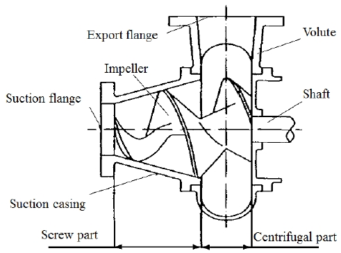
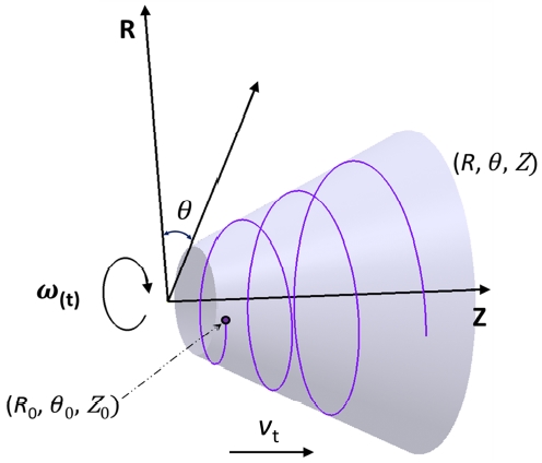
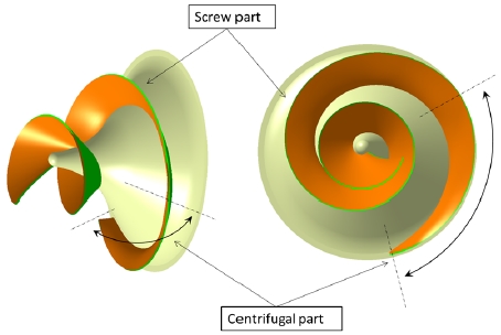
Figure 1 illustrates the 2-D view of a screw centrifugal pump model. This pump model includes two parts, one is screw part, the other one is centrifugal part. A spiral casing is connected with the discharge of impeller. The new design method for this pump model is based on the profile equations of blade. The design explanation is shown in Figure 2. Supposing a point starts from (R0, θ0, Z0), then rotates around the Z-axis at a fixed angular velocity(ωt), and moves along the positive direction of Z-axis at an axial velocity(vt) on the surface(R = f(z)). The result trajectory is a spiral line. Thus, it can be proven that for the determination of a spiral line the essential factors are the angular velocity( ωt), axial velocity(vt) and the generatrix equation(R = f(z)). Under normal condition, the angular velocity is usually a constant, if the axial velocity also is a constant, the spiral line is a equal pitch spiral. Otherwise, it is a variable pitch spiral.
The spiral line can be defined by the following Equation (1) ~ Equation (3) [8].
| (1) |
| (2) |
| (3) |
where ω(t) represents the angular velocity, v(t) is the axial velocity, θ0 is the starting rotation angle and Z0 is the distance of starting point in Z direction.
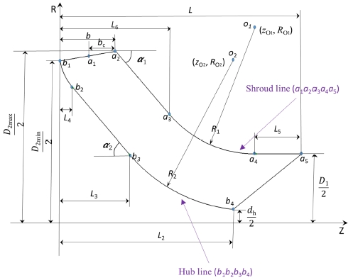
Table 1 shows the design specification of screw centrifugal pump. The capacity coefficient is 0.221 and head coefficient is 0.530, respectively. The meridional shape is illustrated in Figure 3. The main parameters are calculated by the following equations [8].
| (4) |
| (5) |
| (6) |
| (7) |
where Q is the flow rate, n is the rotational speed. ns is the specific speed of screw centrifugal pump. The trap angle of blade shroud line is 781.5˚and trap angle of hub line is 742.5˚, respectively. Moreover, the trap angle of centrifugal part is 112.5˚. The design parameters of meridional shape are listed in Table 2.
The meridional shape has a direct impact on the performance of pump model. The 2-D meridional shape of screw centrifugal pump model is illustrated in Figure 3. The shroud line (a1a2a3a4a5) consists of line-line-arc-line and the hub line (b1b2b3b4) consists of arc-line-arc.
After all the parameters have been determined, the profile spiral equations of blade can be calculated by the following process. In this study, v(t) was set as a constant speed.
| (8) |
| (9) |
where θ is the trap angle and n is the rotational speed. LAxial is the length at axial direction. The profile equations of shroud line are defined as follows:
| (10) |
| (11) |
| (12) |
The profile equations of hub line are defined as follows:
| (13) |
| (14) |
| (15) |
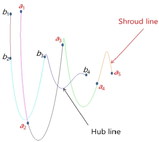
After all the blade profile equations were determined, the shroud and hub profile lines can be drawn using 3-D modeling softwares. In this study, the shroud and hub profile lines are illustrated in Figure 4 and the 3-D modeling of screw centrifugal pump is depicted in Figure 5. The spiral casing used for screw centrifugal pump is a normal centrifugal pump casing. Regarding the previous study [8], the cross section area was enlarged to match the screw centrifugal impeller.
2.2. Numerical method
The numerical simulations are required to further understand the performance and internal flow characteristics of the screw centrifugal pump. This study employs a commercial code of ANSYS CFX to conduct numerical simulations by solving three-dimensional (3D), steady-state, incompressible Reynolds-averaged Navier-Stokes (RANS) equations with a finite-volume solver.
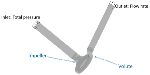
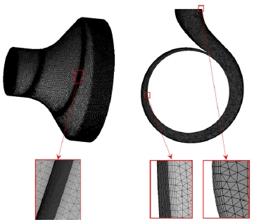
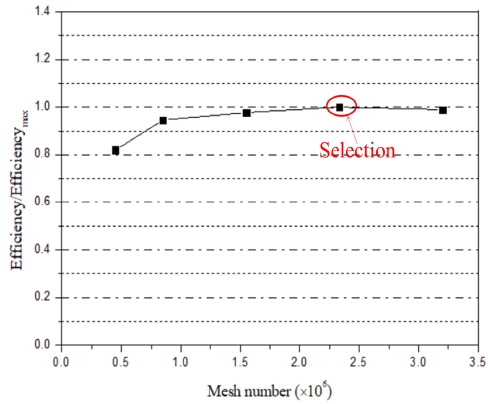
Figure 6 and Figure 7 depict the entire computational fluid domain and numerical grid of the screw centrifugal pump model. Because the blade of screw centrifugal pump model is unique, the hexahedral mesh is difficult to be generated. Therefore, in this study tetrahedral mesh is utilized and the boundary layers also are adopted. The mesh dependence test has been done as shown in Figure 8. Finally, a mesh number of 2.3 × 10⁶ was selected. The numerical methods and boundary conditions are listed in Table 3. The shear stress transport (SST) turbulence model has been well known to estimate both flow separation under an adverse pressure gradient and vortex occurrence on the wall of a complicated blade shape. Therefore, the SST turbulence model is adopted in this study. The total pressure and flow rate are set at the inlet and outlet of the screw centrifugal pump model, respectively. The general connection was set as frozen rotor between the rotational domain and fixed domain.
3. Results and discussion
3.1 performance curves
The screw centrifugal pump is a special type of pump. Considering the hydraulic loss, the efficiency of pump can be calculated by the following equation:
| (16) |
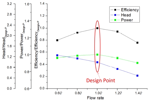
where η is the pump efficiency; T is the input torque; ω is the angular velocity; ρ is the water density; g is the gravity acceleration; Q is the flow rate and H is the head of the pump. Figure 9 shows the performance curve of the screw centrifugal pump model. At the design point, the pump model achieved the best efficiency. Pump head decreased with the increasement of flow rate. The input power increased at first, reached a maximum value, then decreased. The experimental test for validation will be continued after the test model is manufactured, and then the summarized experimental test results will be reported later.
3.2 Loss analysis
The loss analysis of impeller and volute has been conducted by various flow rates. The equations are defined as follows:
| (17) |
| (18) |
HLoss,impeller gives the total loss calculation method only for the impeller of pump. ΔpTotal is the total pressure difference between each component. Where the Hloss gives the total loss calculation method for the each components of pump except impeller. Pinl is the total pressure at the entrance of each component.
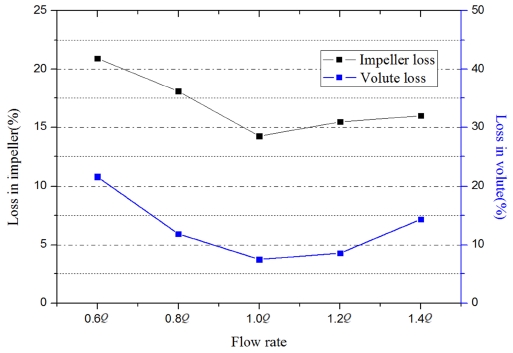
The loss analysis result of impeller and volute at various flow rates is illustrated in Figure 10. When the screw centrifugal pump operates at the design point, the result indicates the minimum loss in impeller and volute. If the volute and impeller do not match, the loss will increase. This indicates the design of impeller and volute achieved the design purpose. Thus, it can be concluded that a proper increase of volute cross section area is beneficial for the screw centrifugal pump.
3.3 Internal flow characteristics
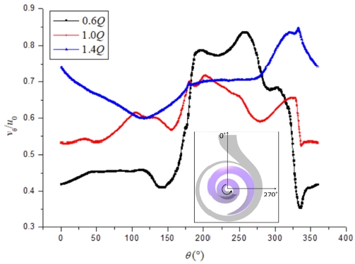
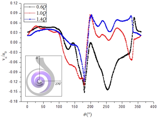
The water flow is discharged from the impeller outlet of the screw centrifugal pump blade, after which, it flows into the spiral casing. The flow uniformity and characteristics around the impeller outlet could be employed to estimate the hydraulic performance of pump impeller. Therefore, it is necessary to investigate the water flow characteristics in this area. Figure 11 presents the tangential velocity ratio distribution at three different flow rates around the impeller outlet as shown in Figure 12.
With the increase of flow rate, the main values of tangential velocity gradually increased. The Y axis is defined as tangential velocity ratio (vθ/u0), where vθ is the tangential flow velocity around the impeller and u0 is the tangential velocity in the periphery of impeller defined by the following equation:
| (19) |
where ω is the angular velocity, r is the radius of impeller.
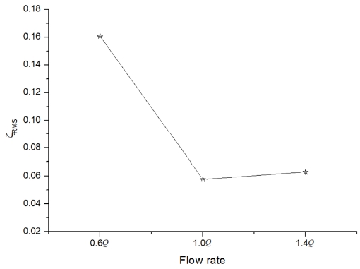
From the tangential velocity ratio distribution, the internal flow characteristics can be predicted. If the fluctuation of tangential velocity distribution is too large, it can be inferred that the axial force of screw centrifugal pump will be significantly large. Additionally, the root mean square (RMS) of normalized tangential velocity ratio fluctuation amplitude was selected to quantify the tangential fluctuation amplitude. The definition of the tangential fluctuation amplitude is as follows:
| (20) |
where the vθ is the tangential velocity, is the averaged tangential velocity, u0 is the tangential velocity in the periphery of impeller. The quantified results were shown in Figure 13. In design point, the tangential velocity fluctuation amplitude was smallest.
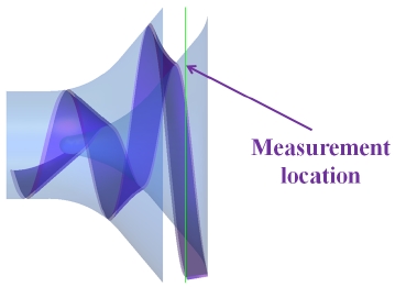
Figure 14 presents the axial velocity ratio distribution in the location as shown in Figure 12. The axial velocity was normalized by axial velocity ratio (vz/u0). If the value of axial velocity is below 0, it means that the flow direction is reversed and there are recirculation flows in this area. From the Figure 14, it was seen that main part of axial velocity distribution is below 0 at the flow rate of 0.6Q. With the increase of flow rate, the negative axial velocity distribution decreased which means that the flow uniformity increased around the pump model outlet. Additionally, there are always recirculation flows existing in the middle part (around 170°) at the three different flow rates.
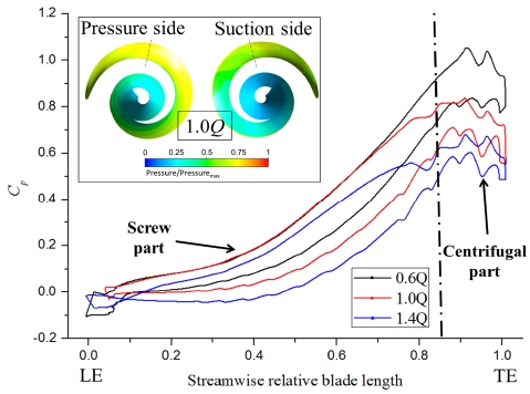
The pressure distribution around the blade of screw centrifugal pump model (0.5 Span) at three different flow rates is illustrated in Figure 15. From the result, it was seen that the pressure at smaller flow rate was higher. That was because the head of pump model increased with the decrease of flow rate, so the internal pressure showed higher value. Moreover, the pressure around the centrifugal part of blade did not change much. The pressure difference mainly occurs in the screw part as shown in the figure. This matches with the previous study [8]. The pressure contour at the design point (1.0Q) is attached in the figure.
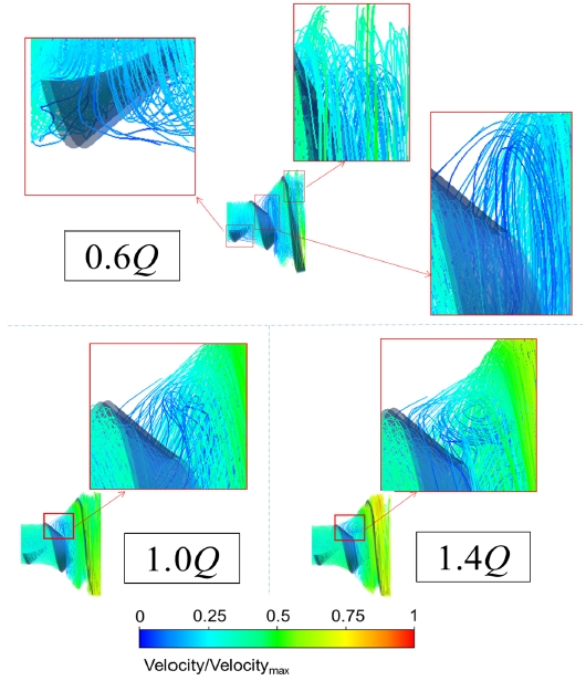
Figure 16 shows the streamline distribution in the impeller of screw centrifugal pump. The flow separation at the flow rate of 0.6Q is quite significant at various locations. With the increase of flow rate to 1.0Q, flow separation near the inlet and outlet disappears, and the strength of flow separation in the middle location of blade decreases. The 1.4Q contour indicates that, the flow separation in the middle is transformed to recirculation flow. It is well known that the flow separation has some negative impacts on the pump performance. The recirculation flows are much more significant and it can substantially decreases the pump performance.
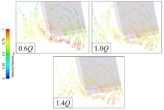
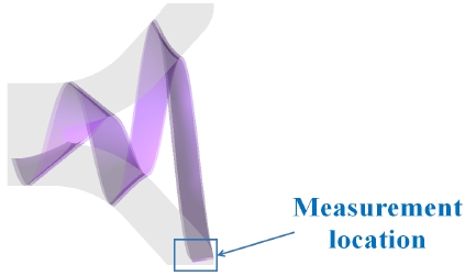
Figure 17 illustrates the vector distribution around the trailing edge of blade at a cross section as illustrated in Figure 18. The trailing edge of the screw centrifugal pump blade could guide the water flow into the spiral casing. The swirling flow usually exists in this area, which could decrease the performance of screw centrifugal pump. Therefore, it is necessary to investigate the water flow characteristics in this area. From the vector distribution, It was seen that there were recirculation flows around the exit position of blade at three various flow rates, which matched with the previous study by Y. Tatebayashi et al. [6].
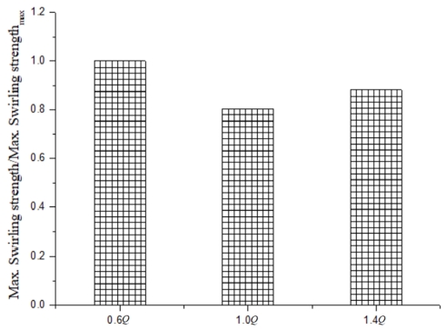
To quantitatively investigate the strength of recirculation flow, the swirling strength values of recirculation flows shown in Figure 17 at three various flow rates are presented in Figure 19. The swirling strength at design point was relatively smaller than those at the flow rate of 0.6Q and 1.4Q.
4. Conclusions
In this study, the profile equations of a screw centrifugal pump model (shroud line and hub line) were derived and three-dimensional modeling was established.
CFD analysis also were performed to check the performance and internal flow characteristics of screw centrifugal pump. The performance and loss analysis result showed that the best efficiency was achieved at the design point. Meanwhile, both of impeller and volute demonstrated minimum loss at design point.
The tangential velocity ratio distribution was studied and the quantified tangential fluctuating amplitude of design point showed a lowest value. From the axial velocity ratio distribution, it can be inferred that the flow uniformity around the pump outlet was improved with the increase of the flow rate.
From the pressure distribution, it was observed that the pressure difference mainly occurred in the screw part. The streamline indicated the internal flow patterns of the pump model. The vector distribution indicated that there were recirculation flows around the exit position of blade at three different flow rates and the swirling strength was weakest at the design point.
Acknowledgments
Author Contributions
Conceptualization, M. Guo, Z. Chen and Y. D. Choi; Methodology, M. Guo; Software, M. Guo and Z. Chen; Validation, M. Guo; Formal Analysis, M. Guo; Investigation, M. Guo; Resources, M. Guo and Z. Chen; Data Curation, M. Guo and Z. Chen; Writing-Original Draft Preparation, M. Guo; Writing-Reviewing & Editing, Y. D. Choi; Supervision, Y. D. Choi; Funding Acquisition, Y. D. Choi.
References
- C. Liu and R. Li, “Experimental investigation of exterior performances and numerical analysis of flow field in a helix centrifugal pump,” Journal of Rocket Propulsion, vol. 3, no. 5, pp. 18-24, 2005 (in Chinese).
- R. Li, B. Li, and W. Han, “Analysis on working characteristics of screw centrifugal pump,” Transaction of the Chinese for agricultural machinery, vol. 12, no. 6, pp. 51-53, 2005 (in Chinese).
-
Y. Tatebayashi, K. Tanaka, and T. Kobayashi, “Thrust prediction in screw-type centrifugal pump,” Proceeding of 4th ASME_JSME Joint Fluid Engineering Conference, Hawaii, USA, 2003.
[https://doi.org/10.1115/FEDSM2003-45105]

-
Y. Tatebayashi and K. Tanaka, “Influence of meridional shape on screw-type centrifugal pump performance,” Proceeding of ASME Fluids Engineering Summer Meeting, Quebec, Canada, 2002.
[https://doi.org/10.1115/FEDSM2002-31183]

- Y. Kim, K. Tanaka, Y. Lee, and Y. Matsumoto, “Effects of entrained air on the characteristics of a small screw-type centrifugal pump,” Jounal of Korean Society for Fluid Machinery, vol. 2, no. 3 pp. 37-44, 1999 (in Korean).
- Y. Tatebayashi, K. Tanaka, and T. Kobayashi, “Thrust prediction in screw-type centrifugal pump,” Proceeding of ASME Fluids Engineering Division Summer Meeting and Exhibition, Houston, USA, 2005.
- ANSYS Inc, ANSYS CFX Documentation, Ver. 18.1, http://www.ansys.com, , Accessed December 6, 2018.
- X. F. Guan, Modern Pump Theory and Design, Beijing, China Astronautic Publishing House, 2011 (in Chinese).

