Effect of J-Groove design parameter on suppression of swirl flow in draft tube of francis hydro turbine
Copyright © The Korean Society of Marine Engineering
This is an Open Access article distributed under the terms of the Creative Commons Attribution Non-Commercial License (http://creativecommons.org/licenses/by-nc/3.0), which permits unrestricted non-commercial use, distribution, and reproduction in any medium, provided the original work is properly cited.
Abstract
Hydropower is the most versatile source of electricity. Francis hydro turbine is a major turbine in contribution to the hydropower sector. Francis hydro turbine operates in a wide operating range from deep partial load to full load condition. While operating in partial load condition, Francis turbine suffers from the unwanted swirl flow. Swirl flow will distort the flow in the draft tube to cause unsteady pressure fluctuation and vortex rope. This pressure fluctuation and vortex rope are the main reason for the vortex-induced vibration in the draft tube. The vibration is an unwanted phenomenon in the hydro turbine and cause of structured failure. Due to this reason, many techniques have implemented in the draft tube for suppression of swirl flow and vortex-induce vibration. J-groove is one of the methods for the suppression of swirl flow in the draft tube of Francis hydro turbine. J-Groove is the simple groove that mounted on the draft tube wall. The major design criteria for J-Groove are the length, depth, and number. The numerical analysis was performed to determine the effect of the J-Groove in the suppression of swirl flow in the draft tube. The performance results from the experiment and CFD analysis have compared for validation of the numerical method. Furthermore, the influence of the design parameter of the J-Groove on the suppression of swirl flow and loss in the draft tube has been studied. Moreover, the proper design criteria for the J-Groove has been set for the suppression of swirl flow in the draft tube.
Keywords:
Francis hydro turbine, J-Groove, Swirl flow, Flow angle, Draft tube1. Introduction
Hydropower is one of the major renewable sources of energy. The stability of the electricity supply from hydropower plant is stable than another renewable source of energy. The turbine needs to operate in various operating conditions to maintain a constant supply of electricity. While operations in different operating conditions like partial flow rate, start-stop, and emergency shutdown are the cause of unsteady pressure fluctuation and viscous wake generation in a draft tube of the turbine [1]. When Francis turbine operates below the normal operating flow condition, the vortex breakdown arises at the outlet of the runner. This breakdown of vortex causes pressure fluctuation and complex flow in the draft tube of the turbine [2]. Goyal et al. [3] experimented with high head Francis turbines. Goyal et al. concluded that the low-velocity region at the center of the draft tube is the cause of the formation of vortex rope and swirl flow [3].
The presence of swirl flow often results in instability flow in the draft tube of hydraulic reaction turbines. At the design point, water turbines generally operate with minimum swirl flow and no flow separations. However, at off-design, the flow leaving the turbine has a large swirling component, which leads to serious one-dimensional pressure pulsations and ultimately leads to draft tube surge [4]. Similarly, the breakdown of spiral vortex causes severe pressure pulsation in the draft tube [5]. Casanova has studied the failure of the bolts that fasten the draft tube of Francis Hydro Turbine [6]. He concluded that the reason for the failure of the bolt is vortex-induced vibration and severe pressure fluctuation in the draft tube. The viscous wake has detected in the draft tube due to rotor-stator interaction from a runner [7]. The rotor-stator interaction between runner and draft tube generates unnecessary pressure pulsation and non-uniform flow [8]. Susan-Resiga et al. [9] have suggested the supply of high-pressure water jet from the crown tip for suppression of pressure fluctuation in the draft tube. Susan-Resiga et al. [10] have evaluated this method numerically. The water jet injection is successful in the suppression of vortex breakdown in the draft tube, but the structure of the jet flow is complex.
Kurokawa et al. [11] proposed shallow grooves mounted on the wall of turbo-machinery for the suppression of the swirl flow. From previous works, it has clarified that J-Groove can suppress swirl flow that occurs in the draft tube. Choi et al. implemented the J-Groove in inducer for the suppression of cavitation [12]. Chen et al. [13]showed that the installation of J-Groove on the wall of the draft tube has an insignificant effect on the performance of the turbine. J-Groove installation has a significant effect on the suppression of swirl flow in Francis turbine [14]. The design parameter of J-Groove has not clarified properly in previous studies. Thus, the effect of different design parameters has been observed in this study.
2. Turbine Model and Numerical Method
2.1 Turbine Model
3 kW-class Francis hydro turbine model operates under design condit effective pressure head H = 15.5 m, flow rate passing through the turbine Q = 0.032 m3/s, rotational speed ω = 188.5 rad/s. The turbine model consists of 9 runner blades, 12 guide vanes, and 12 stay vanes. The inlet and outlet diameters for the runner are 146 mm and 112 mm, respectively. The specific speed (ν) of the Francis turbine model is 0.26.
| (1) |
| (2) |
| (3) |
where φ is flow coefficient, ψ is head coefficient and Rref is outlet radius of runner.
2.2 J-Groove Design
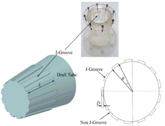
J-Groove is the rectangular groove created on the inner surface of the draft tube. The main parameters for the J-Groove design are the angle (α ), depth (D), length (L), and number (N). The definition and parameters of J-Groove have shown in Figure 1. The relation between the design parameter of J-Groove has still unknown. The design of J-Groove has adapted from Chen [13]. The initial design of J-Groove has L = 120 mm, θ = 15°, D = 4 mm, and N = 12. The list of samples of J-Groove with a variation of design parameters is listed in Table 1. The effect of the individual design parameter of J-Groove has been studied in Francis turbine of specific speed (v) is 0.26. The length of the J-Groove is varied from 90 mm to 140 mm. The depth of J-Groove is varied from 3 mm to 7 mm. The J-Groove angle is varied from 10° to 40°. The number of J-Groove is varied from 4 to 20. The length and depth of J-Groove are normalized by the outlet diameter of the runner (2Rref).
2.3 Experimental Setup
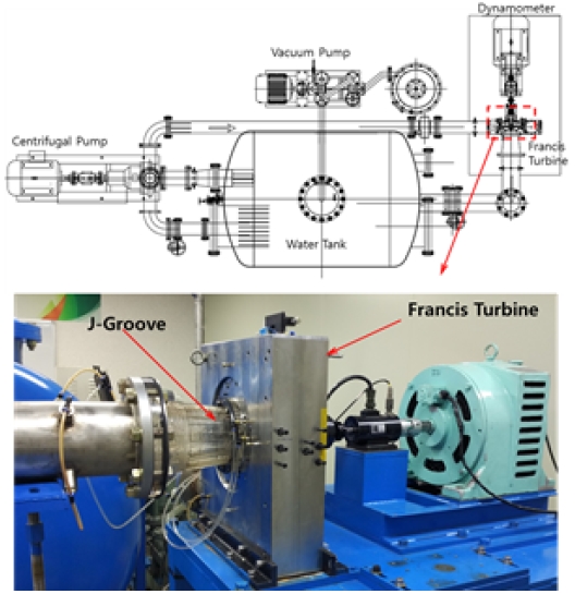
The experiment was performed in the closed system, as shown in Figure 2. The constant head of 15 m has maintained. The flow is circulated in the closed-loop by a centrifugal pump. The performance and pressure fluctuation analysis for the initial J-Groove design has conducted. The experimental results have been used for the validation of CFD analysis results.
2.4 Numerical Method
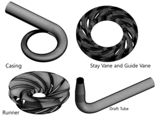
A numerical method for the analysis was adopted from the previous study [15]. The numerical grids for the analysis have generated from ICEM 18.1 [16]. Structured numerical grids are used for CFD analysis. Figure 3 shows the numerical mesh for computational analysis.
Computational Fluid Dynamics (CFD) analysis is an efficient method for investigating the swirl flow characteristics in a hydro turbine. The present study used the commercial CFD code of ANSYS CFX 18.1 [17] to solve the Reynolds averaged Navier-Stokes equations. The mesh of full fluid domains was generated in ANSYS ICEM 18.1 [16]. Table 2 indicates the boundary condition for the flow field.
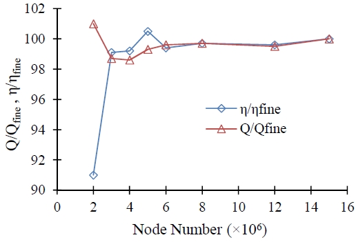
The numerical analysis results depend upon numerical grids. The grids independence test was carried out to determine the optimum number of nodes for the analysis. The result of the grid independence test has shown in Figure 4. The mesh number of 8 million nodes has shown stable results, and thus, the 8 million nodes were selected for further CFD analysis.
3. Results and Discussion
3.1 Performance Analysis of Francis Turbine Model
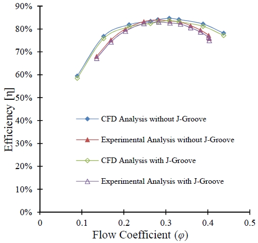
The performance results from the experiment and CFD analysis have been compared for the validation of the numerical analysis. Figure 5 indicates the comparison between experiment and CFD analysis results. The deviation between the experiment and the CFD analysis results is 1.5%. The maximum efficiency for the turbine has achieved at the flow coefficient of 0.308. The performance curves in Figure 5 shows the same tendency between experimental and CFD analysis results. There is a slight deviation in partial and high flow rates between experimental and CFD analysis due to the incompetence of the turbulence model. The installation of J-Groove has slightly improved in the performance of the Francis hydro turbine because the installation of J-Groove improves instantaneous pressure distribution in the draft tube.
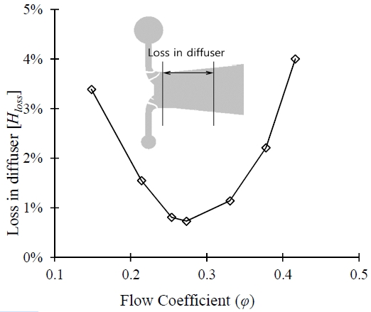
The head loss in the draft tube is used to characterizes the performance of the draft tube. Wilhelm et al. [18] have explained the loss phenomena in the draft tube. The loss in the draft tube is occurred by diffusion and viscous dissipation of mean kinetic energy. Head loss in the diffuser is calculated by using Equation (4) [19]. Figure 6 indicates that the head loss in the diffuser at different flow coefficient. Head loss in diffuser is minimum from φ = 0.25 to φ = 0.32 in a diffuser. Therefore, this is the best operating condition for the turbine.
| (4) |
where, Δpdiffuser is the difference between the pressure at inlet and outlet of the diffuser, ρ is the density of water used as working fluid, g is the acceleration due to gravity.
The head loss in the diffuser is considerably high at the off-design operating condition because of the highly intermittent turbulent flow in the draft tube at off-design conditions. The turbulent flow occurs due to vortex formation in the central and near-wall region.
3.2 Swirl Number Distribution
The main purpose of installing the J-Groove on the wall of the draft tube is to reduce the unsteady pressure fluctuation in the draft tube. And the unsteady pressure fluctuation is related to the swirl flow occurring in the draft tube. The swirl number (γ) is a useful mathematical equation to determine the intensity of swirl flow in a draft tube [20][21].
| (5) |
where, the nomenclatures of vθ, vz, r and R are tangential velocity, axial velocity, the radial distance from the axis, and radius at the outer wall of the diffuser, respectively.
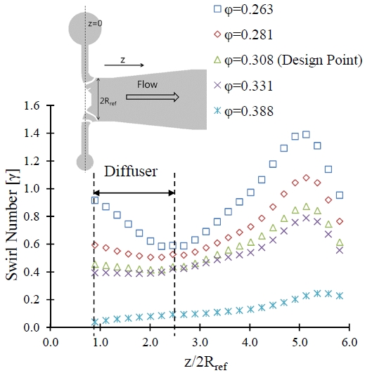
The swirl flow directly depends upon the tangential and axial velocity. The swirl number evaluates the intensity of swirl in the flow. Chigier and Beer [22] explained that the swirl number is an important criterion for determining the swirl intensity in the diffuser. Swirl number is the ratio of angular momentum of tangential velocity to linear momentum of axial velocity. The tangential and axial velocity is dependent on operating conditions. Figure 7 shows the swirl number variation at different flow rate conditions. The swirl number is high at the partial flow condition. When the flow coefficient is increased, the swirl flow in the draft tube has been decreased. The swirl number is minimum in the diffuser, but the intensity of the swirl increases as the flow passes along the draft tube. The swirl number reaches a maximum value of 1.4 at φ = 0.263 at the region downstream of the draft tube.
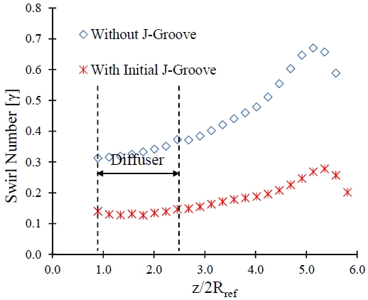
The installation of J-Groove in the Francis hydro turbine does no influence on the performance. The installation of J-Groove helps to suppress the swirl flow in the draft tube. Figure 8 shows that the J-Groove installation drastically improves the swirl flow in the draft tube. The swirl number is distributed uniformly from the exit of the runner to the outlet of a draft tube with the installation of J-Groove. The maximum swirl number has reduced from 0.7 to 0.2 in the draft tube. It implies that the flow in the draft tube is smoother and uniform.
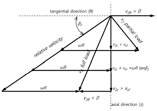
Figure 9 indicates the velocity triangle of Francis hydro turbine at the region downstream of the draft tube. The best operating condition for Francis turbine is swirl-free velocity equals the axial velocity at the downstream of the runner.
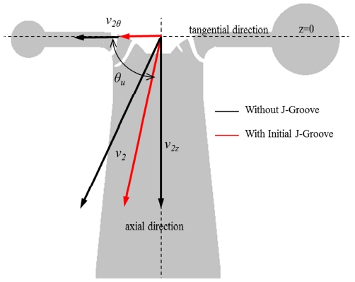
The swirl flow will be low when runner outlet velocity is perpendicular to the tangential direction. The flow angle represents the angle between runner outlet velocity and tangential velocity at runner outlet, as shown in Figure 10.
| (6) |
where θu is the flow angle, v2θ is the tangential velocity at downstream, v2z is the axial velocity in the draft tube
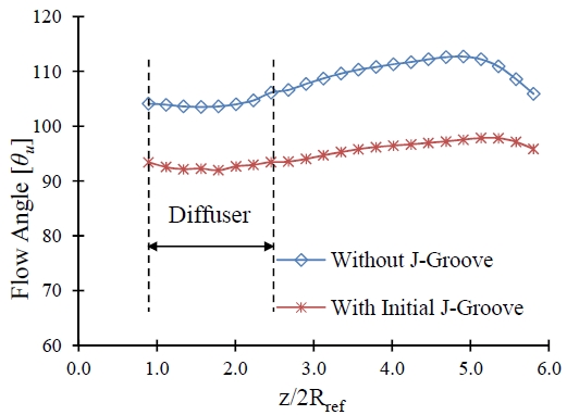
Figure 11 indicates the flow angle distribution in the draft tube. The flow angle should 90° for smother flow in the draft tube. With the installation of the J-Groove, the flow angle is closer to 90º. It indicates that the installation of J-Groove is a good measure to suppress the swirl flow in the draft tube. The flow angle and swirl number are correlated with each other. With a decrease in swirl number, the flow angle gets closer to 90º. With the installation of J-Groove, the flow angle distribution is much smoother than the case without J-Groove installation.
3.3 Effect of J-Groove Length on Swirl Intensity
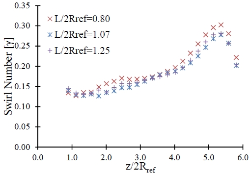
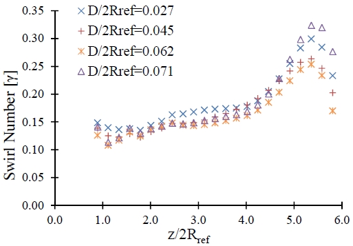
The length of J-Groove has been investigated on the effect of swirl intensity by considering depth (D) is 4 mm, angle (θ) is 15°, and number (N) is 12. The length of J-Groove has normalized with the outlet diameter of the runner. Figure 12 shows the influence of the J-Groove length on the suppression of swirl flow in the draft tube. When the length increases, the swirl number decreases to a certain extent. After the swirl number decrease to its minimum value, then the increase in the length of J-Groove does no influence in suppressing swirl flow.
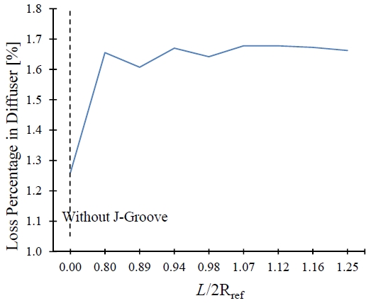
The loss in diffuser has evaluated to determine the suitable length for the J-Groove. Figure 13 shows the head loss in a diffuser. The loss in diffuser remains constant at L/2Rref >1.00. When the L/2Rref < 0.80, J- Groove effect in the suppression of swirl flow is minimum. The analysis of J-Groove has shown that the length of J-Groove should lie in between 0.80 < L/2Rref < 1.00 for maximizing the suppression of swirl flow and minimum head loss.
3.4 Effect of J-Groove Depth on Swirl Intensity
The depth of J-Groove is another important parameter for design. Generally, the swallow J-Groove is preferred. The effect of depth has been studied by considering length (L) is 120 mm, angle (θ) is 15°, and number (N) is 12. Figure 14 indicates the effect of J-Groove depth on the suppression of swirl number. The increase in depth of J-Groove has a positive effect on the suppression of swirl flow.
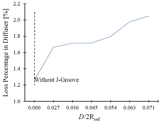
The comparison of head loss with different head has done in Figure 15. Further analysis shows that the increase in depth of J-Groove causes more head loss in a diffuser. When D/2Rref > 0.7, it will increase the head loss drastically from 1.2% to 2.2%. The depth of the J-Groove should be considered in the ranges between 0.030 < D/2Rref < 0.040, which accounts for the suppression of swirl flow and head loss.
3.5 Effect of J-Groove Number on Swirl Intensity
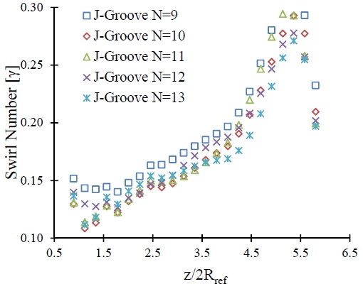
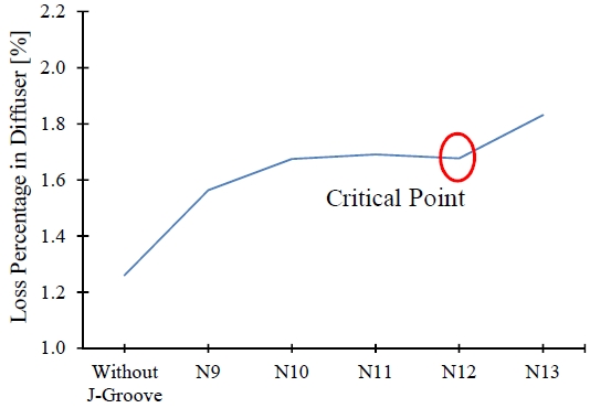
The number is another design constraint for J-Groove. The number of J-Groove is useful to predict the angle and width of J-Groove. J-Groove needs to install circumferentially in a diffuser because the number and the angle of J-Groove are dependent on each other. Figure 16 shows the effect of the J-Groove number in the swirl number, while other parameters are constant. The number of J-Groove has no significant effect on the suppression of swirl number. However, there is a critical number of J-Groove with each J-Groove angle. The critical number is determined by evaluating head loss in the diffuser.
| (7) |
where, α is the J-Groove angle and Ncritical is the critical value of the number of J-Groove for given α.
The critical number of J-Groove maintains an equal distance between two adjacent J-Groove. Figure 17 indicates, when the J-Groove number is beyond the critical value, the head loss increases drastically. The larger width of the J-Groove creates the vortex rope at a wall of the diffuser.
4. Conclusion
The effect of J-Groove design parameters has been studied on the suppression of swirl flow. The internal flow analysis showed that J-Groove installation in the draft tube has a positive effect on the suppression of swirl flow. J-Groove installation helps to decrease the tangential velocity in the draft tube to reduce angular momentum in the tangential direction. The implementation of J-Groove has mitigated the swirl flow in the draft tube. In this study, the influence of J-Groove design parameters of J-Groove on swirl number and head loss were studied. The main aim of J-Groove is to minimize the swirl number and head loss in the draft tube. The improper selection of the design parameter might increase the head loss in the draft tube.
According to internal flow analysis and loss analysis, J-Groove’s effectiveness was determined with a change in design parameters. The major parameters for the J-Groove are the length, depth, and angle of J-Groove. The range of the length and depth for J-Groove should be from 0.80 < L/2Rref < 1.00 and 0.030 < D/2Rref < 0.040 for the proper functioning of J-Groove. The angle of J-groove determines the width and number of J-Groove. There is a critical value for the J-Groove number, which can be determined from the J-Groove angle. The loss analysis indicated that the J-Groove number should be less than the critical value. The proper design of J-Groove can maintain a proper flow angle in different operating conditions in the draft tube. In this study, the J-Groove design parameter has been determined concerning the outlet diameter of the runner. The normalization of the J-Groove design with the specific speed of the turbine will be conducted in the future.
Acknowledgments
This research was supported by New and renewable energy of the Korea Institute of Energy Technology Evaluation and Planning (KETEP) grant funded by Korea Government Ministry of Trade, Industry and Energy (No. 20163010060350).
Author Contributions
Conceptualization, U. Shrestha; Methodology, U Shrestha; Software, Y. D. Choi; Validation, U. Shrestha; Formal analysis, U. Shrestha; Investigation, U. Shrestha; Resources, U. Shrestha; Data Curation, U. Shrestha; Writing-original draft preparation, U. Shrestha; Writing-review and editing, U. Shrestha; Supervision, Y. D. Choi, Funding acquisition, Y. D. Choi.
References
-
C. Trivedi, M. J. Cervantes, B. K. Gandhi, and O. G. Dhalhaug, “Pressure measurements on a high-head Francis turbine during load acceptance and rejection,” Journal of Hydraulic Research, vol. 57, no. 2, pp. 283-297, 2014.
[https://doi.org/10.1080/00221686.2013.854846]

-
A. Favrel, a. Muller, C. Landry, K. Yamamoto, and F. Avellan, “Study of the vortex-induced pressure excitation source in a Francis turbine draft tube by particle image velocimetry,” Experiment Fluids, vol. 56, no. 12, pp. 215-230, 2015.
[https://doi.org/10.1007/s00348-015-2085-5]

-
R. Goyal, M. J. Cervantes, and B. K. Gandhi, “Vortex rope formation in a high head model Francis turbine,” Journal of Fluids Engineering, vol. 139, no. 4, pp. 1-14, 2017.
[https://doi.org/10.1115/1.4035224]

-
P. Dorfler, M. Sick, and A. Coutu, Flow-Induced Pulsation and Vibration in HydroElectric Machinery, London: Springer, 2013.
[https://doi.org/10.1007/978-1-4471-4252-2]

- A. I. Bosioc, C. Tanasa, R. Susan-Resiga, and S. Muntean “Numerical analysis of a swirling flow generated at lower runner speeds,” Conference on Modelling Fluid Flow (CMFF’12), Budapest, 2012.
-
F. Casanova, “Failure analysis of draft tube connecting bolts of a Francis-type hydroelectric power plant,” Engineering Failure Analysis, vol. 16, no. 7, pp. 2202-2208, 2009.
[https://doi.org/10.1016/j.engfailanal.2009.03.003]

-
X. Escaler, J. V. Ekanger, H. H. Francke, and M. Kjeldsen, “Detection of draft tube surge and erosive blade cavitation in a full-scale Francis turbine,” Journal of Fluids Engineering, vol. 137, no. 1, pp. 9, 2015.
[https://doi.org/10.1115/1.4027541]

-
U. Seidel, B. Hubner, J. Lofflad, and P Faigle, “Evaluation of RSI-induced stresses in Francis runners,” IOP Conference Series: Earth and Environmental Science, p. 14, 2012.
[https://doi.org/10.1088/1755-1315/15/5/052010]

- R. Susan-Resiga, T. C. Vu, A. Muntean, and G. D. Ciocan, “Jet control of the draft tube vortex rope in Francis turbines at partial discharge,” Proceedings of the 23rd IAHR Symposium on hydraulic machinery and systems, Yokohama, pp. 17-21, 2006.
- R. Susan-Resiga, S. Muntane, A.L. Bosioc, and A. Stuparu, “Swirling flow apparatus and a test rig for flow control in hydraulic turbines discharge cone,” Proceedings of the 2nd IAHR International Meeting of the Workgroup in Cavitation and Dynamic Problems in Hydraulic Machinery and Systems, Timisoara, pp. 203-216, 2007.
-
J. Kurokawa, S. L. Saha, J. Matsui, and T. Kitahora, “Passive control of rotating stall in a parallel wall vaneless diffuser by radial grooves,” Journal of Fluid of Engineering, vol. 122, no. 1, pp. 90-96, 2000.
[https://doi.org/10.1115/1.483230]

-
Y. D. Choi, J. Kurokawa, and H. Imamura, “Suppression of cavitation in inducers by J-Grooves,” Journal of Fluids Engineering, vol. 129, no. 1, pp. 15-22, 2007.
[https://doi.org/10.1115/1.2375126]

-
Z. Chen, P. M. Singh, and Y. D. Choi, “Suppression of unsteady swirl flow in the draft tube of a Francis hydro turbine model using J-Groove,” Journal of Mechanical Science and Technology, vol. 31, no. 12, pp. 5813-5820, 2017.
[https://doi.org/10.1007/s12206-017-1123-z]

-
Z. Chen and Y. D. Choi, “Suppression of cavitation in the draft tube of Francis turbine model by J-Groove,” Institute of Mechanical Engineers, vol. 233, no. 9, pp. 3100-3110, 2018.
[https://doi.org/10.1177/0954406218802310]

-
Z. Chen, P. M. Singh, and Y. D. Choi, “Francis turbine blade design on the basis of port area and loss analysis,” Energies, vol. 9, no. 3, pp. 164-176, 2016.
[https://doi.org/10.3390/en9030164]

- ANSYS, ANSYS CFX Documentation, ANSYS.Inc, Pennsylvania, 2017.
- ANSYS Inc., ANSYS Customer Portal, [Online]. Available: https://support.ansys.com/AnsysCustomerPortal, ., September 25, 2018.
-
S. Wihelm, G. Balarac, O. Metais, and C. Segoufin “Analysis of head losses in a turbine draft tube by means of 3D unsteady simulations,” Flow Turbulence Combust, vol. 97, no. 4, pp. 1255-1280, 2016.
[https://doi.org/10.1007/s10494-016-9767-9]

-
P. M. Singh, Z. Chen, and Y. D Choi, “Hydraulic design and performance analysis on a small pump-turbine system for ocean renewable energy storage system,” Journal of Mechanical Science and Technology, vol. 31, no. 11, pp. 5089-5097, 2017.
[https://doi.org/10.1007/s12206-017-1002-7]

-
H. J. Sheen, W. J. Chen, S. Y. Jeng, and T. L. Huang, “Correlation of swirl number for a radial-type swirl generator,” Experimental Thermal and Fluid Science, vol. 12, no. 4, pp. 444-451, 1996.
[https://doi.org/10.1016/0894-1777(95)00135-2]

-
R. Susan-Resiga, G. D. Ciocan, I. Anton, and F. Avellan, “Analysis of the swirling flow downstream a Francis turbine runner,” Journal of Fluids Engineering, vol. 128, no. 1, pp. 177-189, 2006.
[https://doi.org/10.1115/1.2137341]

-
N. A. Chigier and J. M. Beer, “Velocity and static-pressure distributions in swirling air jets issuing from annular and divergent nozzles,” Journal of Fluids Engineering, vol. 86, no. 4, pp. 788-796, 1964.
[https://doi.org/10.1115/1.3655954]


