Parametric study of separation control over hemisphere using local wall suction in a circulating water channel
Copyright © The Korean Society of Marine Engineering
This is an Open Access article distributed under the terms of the Creative Commons Attribution Non-Commercial License (http://creativecommons.org/licenses/by-nc/3.0), which permits unrestricted non-commercial use, distribution, and reproduction in any medium, provided the original work is properly cited.
Abstract
An experimental study on separation control in front of a hemisphere by local wall suction was performed in a circulating water channel. A vortical system engirdling a bluff body was targeted to mitigate its effect on the wake region where hairpin vortices shed. Local wall suction caused a change in the static pressure distribution over the hemisphere surface, moving the flow separation point upstream. As the flow detached early from the hemisphere surface, the size of the wake region increased indicating that it took longer to generate the vortices. Flow visualization using a dye system indicated that the frequency of hairpin vortices in the wake region was reduced by 21 ~ 33 % depending on the hemisphere size when suction ratio was 2.2. The reduction in the vortex shedding frequency was attributed to the weakening of the standing vortices by local wall suction, which resulted in a reduction in the inrush in the wake region.
Keywords:
Separation, Hairpin vortex, Standing vortex, Wall suction, Hemisphere1. Introduction
The vortical system is considered as a main feature that sustains turbulence in a boundary layer through interactions with each other. Such turbulent structures result in engineering challenges such as frictional drag, erosion, or vibration in industrial applications. Therefore, several researches for controlling a turbulent flow have been widely conducted.
When fluid particles cannot overcome the adverse pressure gradient created due to the skin friction, the flow near the wall is eventually reversed. Further, the presence of the vortex body accelerates the vortex generation process by creating an unfavorable pressure field around the intersection between the surface and the body. This creates a complex three-dimensional wake around the obstacle that leads to separated flows rolling under the existence of shear flow to form spanwise vortices. Several researches have been conducted to investigate this vortical system through computational modeling and experimental visualization using various shapes of bluff bodies such as tear-drop, wing junction, and cylinders [1]-[6].
To demonstrate the effect of the vortical system on turbulent flow, the mechanism by which the turbulent energy is cascaded to initiate and maintain vortices needs to be verified. However, directly showing how the energy deals with the vortex generation process in the turbulent flow is difficult. Therefore, it is convenient to test and visualize the phenomenon in a laminar boundary layer. In this study, a hemisphere was placed on a flat plate in a laminar flow and dye was supplied to visualize a wake region behind it along with hairpin vortices. Moreover, a standing vortex, known as a necklace vortex or a horseshoe vortex surrounding a hemisphere, was also emerged upstream of a hemisphere due to a strong adverse pressure distribution and brought high momentum fluid into the wake region, thereby actively regenerating hairpin vortices [7].
The purpose of this study was to verify how standing vortices play an important role in providing energy into the wake region to enhance the generation of hairpin vortices. To decrease this activity of standing vortices, a hole was drilled in front of a hemisphere to apply local wall suction. The mechanism behind the vortical system phenomenon was revealed qualitatively through flow visualization and recorded for quantitative analysis of the flow behavior using local suction control.
2. Experimental Setup
2.1 Circulating Water Channel
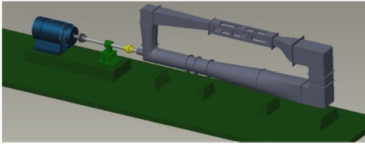
A flow visualization study similar to that by M. S. Acarlar et al. [8] and Y. D. Kang et al. [9] was conducted in a circulating water channel as shown in Figure 1 with 12.5 m, 2.2 m, and 5.8 m as its length, width, and height, respectively. The circulating water channel could run up to 2.0 m/s with ±2 % of the velocity distribution at 1.0 m/s. The cross- section of the channel was 1.8 m wide and 0.4 m deep where a test plate with an elliptical leading edge of 1.2 m in length was placed horizontally. This test plate was suspended at a distance of 0.14 m from the bottom. A 0.6 m long flap was connected to the end of the flat plate and its angle was adjusted to prevent flow separation at the leading edge, which was set to 10°.
The Reynolds number (Re) was 3.6 × 10⁴ with the free stream velocity (U∞) of 0.12 m/s to ensure that the flow could be kept as laminar flow at the test section.
| (1) |
Here, x is the streamwise distance from the leading edge and ν is the kinematic viscosity of water, which is 1.01 × 10⁻⁶ m2/s. The origin of the coordinate system is at the center of the hemisphere.
In addition, Re, based on the diameter of the hemisphere (d), was 2.4 × 10³ when d = 24 mm, 4.8 × 10³ when d = 44 mm, 5.9 × 10³ when d = 54 mm, and 1.2 × 10⁴ when d = 94 mm. A pitot tube system was used to measure a free stream velocity.
2.2 Hemisphere and Dye Supply System
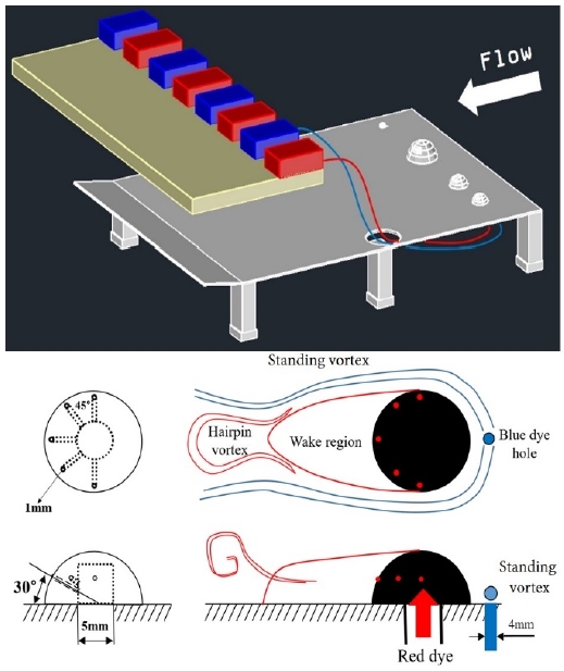
The configuration of a dye supply system at a test section is shown in Figure 2. Each hemisphere was connected to a red tank controlling flow rate with peacock valve. The dye was supplied through a 5.0 mm hole inside the hemisphere and, then, passed through five small holes having 1.0 mm diameter drilled at intervals of 45° on the surface. Thus, the wake region and the hairpin vortex street were visualized using the red color dye. The extreme right-hand side of Figure 2 also shows a hole of 4.0 mm in diameter located at 3.0 mm upstream of the hemisphere’s front, which was used to visualize the standing vortex using a blue color dye. For the control case, this hole was also used to weaken the strength of the standing vortex.
3. Flow Visualization Results
As shown by several researchers, vortices constantly interact with each other and cascade the energy inside the turbulent boundary layer to sustain. In other words, the vortical system forming around obstacles enhances the initiation of vortices and causes mechanical issues in several engineering applications. With respect to the control of standing vortices, a passive control, like a streamline shape, is a suitable way to eliminate the vortical system with a favorable pressure gradient around the obstruction. Alternatively, an active control, such as the suction used in this study, can also reduce their effects on the interaction in shedding vortices.
M. S. Acarlar et al. [10] and H. A. Zondag [11] suppressed the standing vortex generation by using a teardrop shape. They concluded that the standing vortex plays a key role in supplying high momentum into the wake region along with destabilizing the separation point over the obstacle. Their report indicated that the presence of the standing vortex enhances the shedding frequency of hairpin vortices from the wake region. However, W. J. Devenport et al. [12] reported that a passive control methodology could not effectively modify the flow behind a wing-body junction. They proposed that an active control device would be more efficient in changing separation at the leading edge instead of a fillet shape. Therefore, localized surface suction [13] was applied to the turbulent junction flow. It targeted necklace vortices to decrease their maximum diameter and vorticity.
3.1 Qualitative Characteristics of the Wake Region
A visualization experiment with dye injection in circulating water channel was performed to understand the development of shedding vortices behind the hemisphere in the laminar boundary layer. A spanwise vortex was initially developed by the adverse pressure gradient and then by engirdling the flanks of the hemisphere. Depending on the shape of the bluff bodies and Re, the vortical system formed in different ways [6]. After the incoming flow separated from both the flanks, flow reversal occurred at the back of the hemisphere that went up to the separation point. While encountering the cross-flow, a spanwise vortex transformed into a hairpin vortex from the wake region. In addition, two standing vortices were identified in this study.
Local wall suction was directly applied to the standing vortices to carefully study the behavior of the vortex street from the wake region. Two dye colors were used to visualize the flow field around the hemisphere. Blue color dye was emitted from the hole upstream of the hemisphere, while red color dye was fed through the five holes of the hemisphere surface.
The interaction between the standing vortex surrounding the hemisphere and the shedding vortex from the wake region is shown in Figure 3 (a). The flow visualization image was recorded using an iPad Pro with 3840 × 2160 pixels at 30 fps from which the hairpin vortex shedding frequency was estimated. Figure 3 also shows the outline of the flow phenomena around the hemisphere compared to images without and with the control case.
3.2 Control Mechanism
The outline of the control mechanism by local wall suction is presented in Figure 4. It shows the streamwise area of the wake region and the standing vortices surrounding the hemisphere. The left column is for the base case and the right column is with local wall suction. In Figure 4, the upper part shows the plan view and lower part shows the side and the end views.
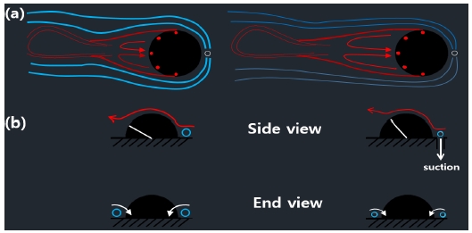
Outline of control mechanism for base case in the left column and for local wall suction upstream of the hemisphere in the right column. (a) Plan view and (b) Side and end views.
There are inner and outer standing vortices as depicted in Figure 4 (a). Apparently, the inner vortex strongly interacted with the wake region and continuously supplied the high-speed fluid due to the vorticity direction. Therefore, these vortices were the source of shedding hairpin vortices behind the hemisphere. In the side view of Figure 4 (b), it can be seen that the separation point has moved upstream and the size of the standing vortex has shrunk in the end view. This occurred because local wall suction weakened a circulation of standing vortices [14]-[17]. This situation is similar to uniformly flowing over a circular cylinder at low Re, where the shedding frequency from the cylinder reduces when the separation point has moved upstream with a reduction in Re. As a result of flow stabilization due to local wall suction, the shedding frequency decreased. As local wall suction suppressed standing vortices and stabilized flow field around the hemisphere, the reduction of the shedding frequency can be expected [8].
3.3 Shedding Frequency
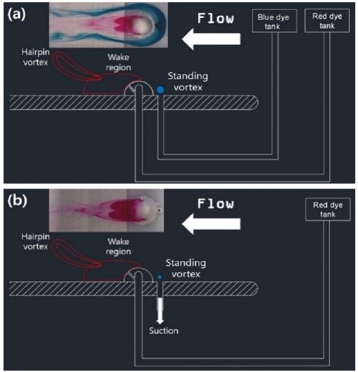
The visualization results with dye are depicted in Figure 5. A base case without suction is depicted in Figure 5 (a), while Figure 5 (b) is for a control case. During control, the front dye injection hole was used to suck so that only red colored dye was supplied. Local wall suction was intrigued by the gravity of water through a tube, whose velocity VSUCK = 0.27 m/s was calculated after measuring the time required to fill a 140 ml beaker. The suction profile in time continued to be rectangular as long as the water level did not noticeably change as the flow was constantly discharged by gravity through the tube connected at the outside of the water tunnel. The strength of suction defined as the suction ratio (SR) was set to 2.2 during the entire experiment.
| (2) |
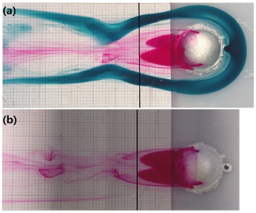
Flow visualization around a hemisphere (d = 44 mm) for (a) base case and (b) control case with a local wall suction
Here, U∞ is the free stream velocity and VSUCK is the velocity of local wall suction. The constant suction rate was ensured by the gravity of the water mass through the front hole of the hemisphere.
Local wall suction further extended the wake area of the hemisphere downstream, although it is difficult to observe the change in the width. When SR = 2.2, the length increased to 2.5 mm with 44 mm diameter as indicated by the black line in Figure 5 (b). The suction control appeared to reduce the velocity of the incoming flow and move the separation point upstream, thereby increasing the length of the wake region. This is consistent with the experimental results of Zondag [11], who proved that a droplet shape (a streamlined obstacle) has a wider wake region because of the absence of standing vortices.
The recorded video was visually analyzed to compute the shedding frequency from the wake region. It was calculated using the total number of hairpin vortices within 30 s. Local wall suction was applied to reduce the effect of standing vortices by mitigating the adverse pressure distribution, leading to an early start to flow separation. Therefore, the reversal flow took more time to develop from the longer wake region.
According to flow visualization analysis, the frequency of hairpin vortex shedding was reduced from 21 % to 33 % depending on the hemisphere size for the suction ratio of 2.2. As a result of targeting the inner standing vortex, the backflow into the formation area of the hairpin vortex at the edge of the wake area was clearly retarded, thereby decreasing the shedding frequency.
The Strouhal number (Sr) is a dimensionless number that expresses the vibration phenomenon of the natural flow and had a value of 0.23 for our study. The suction ratios were more or less the same regardless of the hemisphere diameters. The above data are summarized in Table 1.
| (3) |
In Equation (3), f is the shedding frequency of the hairpin vortices and R is the hemisphere radius.
4. Conclusions
Flow visualization was conducted in the circulating water channel to study the effect of the standing vortex on the shedding frequency behind the hemisphere in a laminar flow. Throughout the experiment, red-colored dye was used for visualizing the hairpin vortices and wake region, while blue-color was used to expose the standing vortices. In the visualization results, , which describes the flow oscillation frequency, was found to be approximately 0.2, irrespective of the size of hemispheres.
For active control on standing vortices, local wall suction was directly applied under them through a test plate in front of hemispheres. It mitigated their vorticity that led to pressure distribution changes, thereby resulting in early occurrence of the separation process. Therefore, the length of the reversal flow further increased downstream. This indicated that the hairpin vortex frequency in the wake region increased up to 33 % when the suction ratio was 2.2. It is speculated that the inner standing vortex could not bring high momentum into the wake region. Experiments by M.S. Acarlar et al. [8] and H. A. Zondag [11] used a teardrop shape to show that standing vortices were not generated and had a lower frequency than the hemisphere because of the weak adverse pressure gradient. The reason behind frequency reduction due to local wall suction was the stabilization of the vortical system around the obstacle and a decrease in the interaction between the wake region and standing vortices.
The effects of suction control can be summarized as follows:
1) An unfavorable pressure distribution over the hemisphere was created, causing the separation to occur early.
2) The length of the wake region was increased such that the reversal flow took longer to shed.
3) The strength of standing vortices near the wake region was reduced so that they could not actively supply high-speed velocity to the inside.
Acknowledgments
This research was supported by Changwon National University in 2019~2020.
Author Contributions
Conceptualization, B. Koo and Y. D. Kang; Methodology, B. Koo; Software, B. Koo; Validation, B. Koo and Y. D. Kang; Formal Analysis, B. Koo; Investigation, B. Koo; Resources, B. Koo; Data Curation, B. Koo; Writing— Original Draft Preparation, B. Koo; Writing—Review & Editing, Y. D. Kang; Visualization, B. Koo; Supervision, Y. D. Kang; Project Administration, Y. D. Kang; Funding Acquisition, Y. D. Kang.
References
-
C. J. Baker, “The position of points of maximum and minimum shear stress upstream of cylinders mounted normal to flat plates,” Journal of Wind Engineering and Industrial Aerodynamics, vol. 18, no. 3, pp. 263-274, 1985.
[https://doi.org/10.1016/0167-6105(85)90085-6]

- J. J. Greco, The Flow Structure in the Vicinity of a Cylinder-Flat Plate Junction : Flow Regimes, Periodicity, and Vortex Interactions, MS Dissertation, Mechanical engineering and mechanics, Lehigh University, USA, 1990.
-
C. M. Hung, C. H. Sung, and C. L. Chen, “Computation of Saddle Point of Attachment,” AIAA Journal, vol. 30, no. 6, pp. 1561-1569, 1992.
[https://doi.org/10.2514/3.11101]

-
J. Y. Hwang and K. S. Yang, “Numerical study of vortical structures around a wall-mounted cubic obstacle in channel flow,” Physics of Fluids, vol. 16, no. 7, pp. 2382-2394, 2004.
[https://doi.org/10.1063/1.1736675]

-
A. S. W. Thomas, “The unsteady characteristics of laminar juncture flow,” Physics of Fluids, vol. 30, no. 2, pp. 283-285, 1987.
[https://doi.org/10.1063/1.866374]

-
M. R. Visbal, “Structure of laminar juncture flows,” AIAA Journal, vol. 29, no. 8, pp. 1273-1282, 1991.
[https://doi.org/10.2514/3.10732]

- Y. D. Kang, Direct Intervention of Hairpin Vortices in a Boundary Layer to Reduce Friction Drag, Ph.D. Dissertation, Department of Mechanical, Materials and Manufacturing Engineering, University of Nottingham, UK, 2009.
- M. S. Acarlar and C. R. Smith, Report FM-5, Department of Mechanical Engineering & Mechanics, Lehigh University, USA, 1984.
-
Y. D. Kang and N. H. An, “A study on separation control by local suction in front of a hemisphere in laminar flow,” Journal of the Korean Society of Marine Environment & Safety, vol. 24, no. 1, pp. 92-100, 2018.
[https://doi.org/10.7837/kosomes.2018.24.1.092]

-
M. S. Acarlar and C. R. Smith, “A study of hairpin vortices in a laminar boundary layer. Part 1. Hairpin vortices generated by a hemisphere protuberance,” Journal of Fluid Mechanics, vol. 175, pp. 1-41, 1987.
[https://doi.org/10.1017/S0022112087000272]

- H. A. Zondag, The Dynamics of Hairpin Vortices in a Laminar Boundary Layer, Ph.D. Dissertation, Department of Applied Physics, University of Eindhoven, Netherlands, 1997.
-
W. J. Devenport, N. K. Agarwal, M. B. Dewitz, R. L. Simpson, and K. Poddar, “Effects of a fillet on the flow past a wing-body junction,” AIAA Journal, vol. 28, no. 12, pp. 2017-2024, 1990.
[https://doi.org/10.2514/3.10517]

-
C. V. Seal and C. R. Smith, “The control of turbulent end-wall boundary layers using surface suction,” Experiment in Fluids, vol. 27, pp. 484-96, 1999.
[https://doi.org/10.1007/s003480050373]

-
A. K. Gupta, “Hydrodynamic modification of the horseshoe vortex at a vertical pier junction with ground,” Physics of Fluids, vol. 30, no. 4, pp. 1213-1215, 1987.
[https://doi.org/10.1063/1.866270]

-
T. L. Doligalski, C. R. Smith, and J. D. A. Walker, “Vortex interactions with walls,” Annual Review of Fluid Mechanics, vol. 26, pp. 573-616, 1994.
[https://doi.org/10.1146/annurev.fluid.26.1.573]

-
D. P. Rizzetta, “Numerical simulation of turbulent cylinder junction flowfields,” AIAA Journal, vol. 32, no. 6, pp. 1113-1119, 1994.
[https://doi.org/10.2514/3.12109]

-
C. V. Seal, C. R. Smith, and D. Rockwell, “Dynamics of the vorticity distribution in endwall junctions,” AIAA Journal, vol. 35, no. 6, pp. 1041-1047, 1997.
[https://doi.org/10.2514/2.192]


