Characteristics of natural convective heat transfer in a vertical minichannel with two grooves
Copyright © The Korean Society of Marine Engineering
This is an Open Access article distributed under the terms of the Creative Commons Attribution Non-Commercial License (http://creativecommons.org/licenses/by-nc/3.0), which permits unrestricted non-commercial use, distribution, and reproduction in any medium, provided the original work is properly cited.
Abstract
The heat transfer characteristics were investigated in a vertical minichannel with two grooves. The wall geometry of the minichannel possessed grooves with several modified groove ratios. To determine the effects of natural convective heat transfer, the finite volume numerical method was used. The results showed that when d/D = 0.1 and d/D = 0.25, there was no flow separation. When d/D = 0.4, however, there was flow separations at both walls. For the left wall, the local Nusselt number decreased dramatically starting at the leading edge. For the case of two grooves, there were four flow separations at d/D = 0.5. The heat transfer patterns were similar to the single-groove case. However, at the end-section of the first groove, the temperatures dispersed downstream. These heat transfer characteristics corresponded to the flow field. When there was a 1-mm distance between the grooves, the Nusselt number showed a larger variation compared to the other cases. When the channel pitch was 3 mm, the distance between the grooves was not a large factor after a 2-mm groove distance was reached.
Keywords:
Natural convection heat transfer, Finite volume scheme, Groove, Minichannel1. Introduction
Plain-fin type heat exchangers have seen industrial use for many decades; however, recently the demand for higher-performing heat exchangers has been increasing. In order to account for this demand, a more compact area between the two vertical materials of a heat exchanger is required to maximize the heat transfer area while confining the volume. The pitches between the vertical plain-fins may be closely positioned so that the flow characteristics approach a microchannel regime. This type of heat exchanger is called a micro heat exchanger or a micro-scale heat exchanger. Before the pitch between the plain-fins is considered to represent a microchannel, the channel pitch becomes a minichannel. Although this is not as compact as a microchannel, it is still more compact than conventional heat exchangers. A minichannel is not a newly emerging technology. However, it is highly recommended to obtain a high heat transfer without requiring an active thermal method. According to Ghobadi and Muzychka [1], the definition of a minichannel ranges between 200 μm to 3 mm based on the hydrodynamic diameter.
Hejcik and Jicha [2] gave a detailed description of the single-phase heat transfer in minichannels. They suggested an evaluation model for circular minichannels and proposed the minimization of the longitudinal thermal conductivity and increase of the accuracy of measurements. Ghasemi, Ranjbar, and Hosseini [3] showed the thermal and hydrodynamic characteristics of water-based suspensions in a novel minichannel heat sink. They showed the heat sink performance in terms of the Nusselt number, friction factor, thermal resistance, and pumping power.
Conder and Solovitz [4] presented a computational optimization of a groove-enhanced minichannel. They obtained an improved performance via surface modification and determined the optimal geometry and Reynolds numbers to achieve an improved thermal performance. They also showed that the modified geometry enhanced the overall heat transfer coefficient by 20%. Ijam, Saidur, and Ganesan [5] researched the cooling of a minichannel heat sink using nanofluids. They anticipated the excellent heat dissipation of these systems for use in next generation electronic devices and used nanofluids as the working fluid in the minichannel. The authors of the current paper have also performed several works on natural convection heat transfer [6][7].
2. Mathematical Modeling
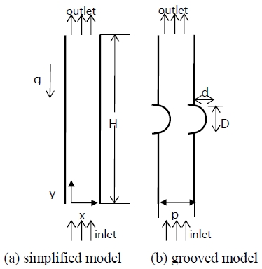
The numerical analysis simulated a portion of a plain-fin tube heat exchanger, which has a stack of minichannels aligned in vertical plain plates [6]. When the distance between the vertical plain-fins is reduced, the confined geometry can permit the incorporation of more fins, and the total heat transfer area will therefore increase. The flow characteristics will also change as different pitches between the vertical plates are used. When the distance between these plates is small, slight rarefaction effects will occur. In this kind of slip-flow regime, the Navier–Stokes equations can be used in conjunction with the velocity-slip and temperature-jump conditions. In this study, the channel pitch is confined to a minichannel. A parametric view of the simplified geometry used in the present study was determined, as shown in Figure 1 (a). The geometry of a grooved model is shown in Figure 1 (b). The groove diameter is indicated by D and the groove depth by d.
Two-dimensional governing equations, including the conservation of mass, the conservation of momentum, and the conservation of energy for steady, laminar, and impressible flow with the property of variable density, are used. Considering the variable density, which is a function of temperature only, the Bossinique approximation model is applied. The governing equations are as follows [7]:
Conservation of mass:
| (1) |
Conservation of momentum:
| (2) |
| (3) |
Conservation of energy:
| (4) |
where
The velocity boundary conditions for the computational domain are as follows:
At the inlet
| (5) |
At the inlet
| (6) |
At the wall, no-slip boundary conditions are applied. The two vertical walls are subjected to constant heat flux conditions.
In heat transfer, the Rayleigh number characterizes a fluid’s flow by showing the ratio of the strengths of thermal transports due to buoyancy in relation to thermal conduction. When the heat flux (q) is specified as a given boundary condition, the temperature difference (ΔT) is not determined. To determine the heat transfer coefficient (h ≡ q / ΔT), ΔT must first be specified. Thus, the Rayleigh number is more complicated in this instance than when a constant temperature condition is used. To avoid iterating, ΔT must be eliminated from the Rayleigh number calculation. A modified Rayleigh number, Ra, is therefore used and is defined as Ra = GrPrNu, where Gr is the Grashof number and Pr is the Prandtl number. The Grashof number represents the ratio of the strengths of the buoyant and viscous forces, and the Prandtl number represents the ratio of the strengths of the momentum diffusion to the thermal diffusion.
Finally, for the constant heat flux boundary condition, the modified Rayleigh number is defined as:
| (7) |
To calculate the heat transfer performance, the average Nusselt number with the characteristic length, Lc, is evaluated using the following equation:
| (8) |
where h is the average heat transfer coefficient, Lc is the characteristic length, and k is the thermal conductivity.
This Nusselt number is the ratio between the time required for thermal transport via diffusion and the time required for thermal transport via flow at the axial speed. The Nusselt number is expected to depend on a number of factors, such as the thermal conductivity, heat capacitance, and viscosity.
Considering the computational method, the finite volume method is used to calculate the numerical solution of the system of governing equations. For the velocity and temperature calculations, a PISO algorithm is used. For the pressure, the body-force weighted algorithm is used to obtain better convergence when a variable density is used. For the present computation, the commercial software ANSYS Fluent [8] is used. For the fluid domain calculation, the user defined function written in the C language is used.
To determine the thermal characteristics of the vertical minichannel plates, the computational domain is selected as a vertical channel, as displayed in Figure 1 (a). The inlet and outlet boundaries are assumed to be fully developed flow, and the thermal boundary at the walls is assumed to be at a constant temperature.
To ensure the reliability of the numerical results, the following formulations suggested by Churchill and Chu [9] and Bayley [10] are compared to obtain the average heat transfer coefficients. Churchill and Chu [9] suggested the following equation based on experimental data:
| (9) |
Bayley [10] proposed a differing the experimental equation:
| (10) |
The results of Equation (9) and Equation (10) were compared using a 3-mm pitch as the minichannel limit. The results of this comparison showed over a 20% discrepancy.
Table 1 shows the grid dependence of the numerical simulation. The total heat transfer rate was calculated at the left wall. The results show that once the node number exceeds 25925, the different grid node cases only differ in terms of the thousandths of the calculated heat transfer rate values.
3. Results and discussion
This study investigated the effects of using grooves in a vertical minichannel on the fluid flow and heat transfer characteristics via laminar free convection. First, to determine the effects of the vertical channel characteristics, simulations were carried out using 1- to 4-mm pitches. Following this, the channel height was varied from 20 to 35 mm.
Table 2 shows the heat transfer rates with the variation of the channel pitches. For these simulations, the channel pitch is relatively small compared to the convectional channel width. The heat transfer rates were calculated at the left wall of the channel. The results showed a linear increase in the heat transfer rate as the channel pitches increased. This is because when the channel pitch increases, so does the flow rate. The thermal transport phenomena will therefore occur more actively, corresponding to the Reynolds analogy.
Table 3 shows the heat transfer rate with varying channel heights. The lower portion of the channel has a large thermal gradient, indicating a large heat transfer, while the upper portion of the channel does not demonstrate further heat transfer. After a 30-mm channel height was reached, no further heat transfer enhancement was observed.
A grooved channel was simulated using groove diameter to groove depth ratios (d/D) of 0.1, 0.25, and 0.4.
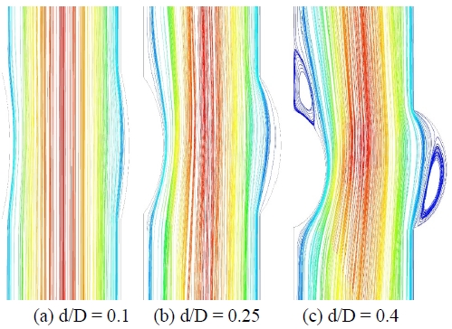
Figure 2 shows the flow streamlines near the grooved sections, which are located in the middle of a vertical minichannel with p/H = 0.1. For the first case of d/D = 0.1, the streamlines showed no separation of flow. For the second case of d/D = 0.25, the flow pattern was similar to that of the first case. At the grooved area, the streamlines began to separate from the wall surface. At d/D = 0.4, flow separation occurred on both sides of the grooved section. This means that the left section has a flow separation, and at the upper left part of the grooved section there is another separation. This kind of flow mixing improves the heat transfer characteristics of the channel.
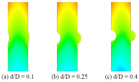
Figure 3 shows the temperature contours for the different groove geometries. In Figure 3, the temperature contours differ starting from the leading edge. Near the left wall, an area of higher temperature is shown in Figure 3 (c) in comparison to that shown in Figure 3 (a). The total heat transfer rate for each case (d/D = 0.1, 0.25, and 0.4) was 10.03 W, 10.16 W, and 10.39 W, respectively. For all cases, Ra = 1000 was used, and the heat transfer was slightly improved as the d/D ratio increased.
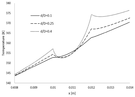
Figure 4 shows the temperature variation in the axial direction along the left-hand wall near the grooved section. At d/D = 0.1, the temperature variation was not very large. However, when the d/D ratio was increased, the temperature variation increased. When d/D = 0.4, indicating a deeper groove, the temperature difference was large. This phenomenon corresponds to the results obtained for the flow characteristics.
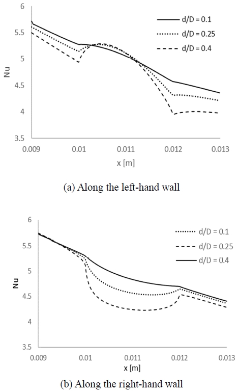
Figure 5 shows the local Nusselt numbers around the groove. For d/D = 0.1 in Figure 5a, the heat transfer coefficient increased as the flow velocity increased along the left-hand wall. At the same height, similar flow patterns and thermal behaviors were observed at the right-hand wall. In this case, as the flow velocity was reduced, the heat transfer decreased. When d/D = 0.4, the flow showed a separation pattern. The Nusselt number showed a significant decrease just after the leading edge of the groove in Figure 5a. However, in Figure 5b, the heat transfer was reduced throughout the separated flow region in the groove. When the flow velocity was reduced in the grooved section, the local Nusselt number decreased.
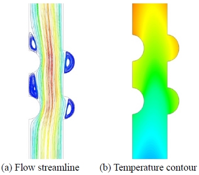
Figure 6 shows the flow streamlines and temperature contours for two grooves with d/D = 0.5 and p/H = 0.1. Flow separation occurred at four locations. At the leading edge of the first groove the flow velocity increased, thereby increasing the heat transfer. However, from the ending edge of the first groove to the leading edge of the second groove, the flow velocity decreased, resulting in a reduction of the heat transfer. At the leading edge of the first groove along the right-hand wall the flow velocity increased, and the heat transfer increased correspondingly. At the upper section of the second groove, the temperature increased.
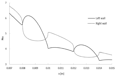
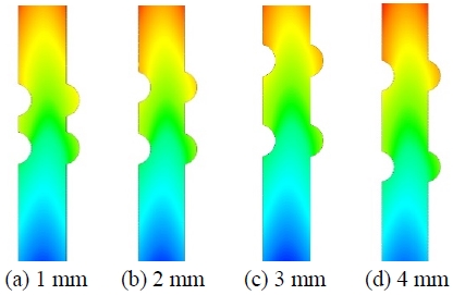
Figure 7 shows the local Nusselt numbers around the two grooves. At the first leading edge of the left-hand wall, the Nusselt number rapidly increased. After the first groove along the left-hand wall, the local Nusselt number continued to increase, and the second largest increase occurred at the second groove. Along the right-hand wall, the local Nusselt number changed dramatically around the first groove and a similar pattern occurred at the second groove. Figure 8 shows the temperature contours with varying distances between the two grooves. The distances in Figure 8 were varied from (a) 1 mm to (d) 4 mm by 1-mm increments. Around the first groove, the temperature profiles showed similar patterns for all four cases. However, at the second groove along the right-hand wall, the temperature increased noticeably as the distance between grooves was increased.
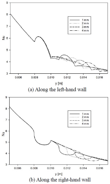
Figure 9 shows the local Nusselt number variations around the two grooves with different groove distances along the (a) left-hand and (b) right-hand walls. For all four cases, the Nusselt numbers varied similarly from the leading edge to the ending edge of the first groove. After this point, the Nusselt numbers varied according to the flow directions. This can be assumed to be a result of the Reynolds analogy. For the 1-mm distance, the Nusselt number showed a larger variation compared to the other cases. When the channel pitch was 3 mm, the distance between the grooves was not a large factor when it was greater than 2 mm. It is also notable that the Nusselt number variation at the right-hand wall was not large compared to that at the left-hand wall.
4. Conclusions
The natural convention heat transfer in a two-dimensional channel with grooves of differing geometries was analyzed using a finite volume method. The grooves were located in the middle section of the channel. The results showed that when d/D = 0.1 and d/D = 0.25, there was no flow separation. However, when d/D = 0.4, flow separations were observed on both sides of the channel. For the left-hand wall, the local Nusselt number decreased at the leading edge. Additionally, the difference between the leading edge and ending edge increased when d/D increased. Considering d/D = 0.4 and p/H = 0.1 with two grooves, four flow separations were observed around the grooves. At the ending section of the first groove, the temperature was varied. At a 3-mm channel pitch, the groove distance was determined to not be a large factor in the Nusselt number variation if it is greater than 2 mm.
Nomenclature
| L : | Total vertical length |
| Nu : | Nusselt number |
| P : | Pressure |
| Pr : | Prandtl number |
| Ra : | Rayleigh number |
| T : | Fluid temperature |
| X : | Cartesian coordinate (horizontal) |
| y : | Cartesian coordinate (vertical) |
| ui : | Velocity components |
| β : | Volumetric thermal expansion coefficient |
| ρ : | Density |
| μ : | Dynamic viscosity |
| cp : | Specific heat at constant pressure |
| k : | Thermal conductivity of a fluid |
Subscripts
| fd : | Fully developed |
| c : | Characteristic length |
Acknowledgments
“This work was supported by a Research Grant of Pukyong National University (2017 year)”
Author Contributions
Conceptualization, E. Kim; Methodology, E. Kim; Software, E. Kim; Validation, E. Kim; Formal analysis, E. Kim; Investigation, E. Kim; Resources, E. Kim; Data Curation, E. Kim; Writing-original draft preparation, E. Kim; Writing-review and editing, E. Kim; Funding acquisition, E. Kim.
References
-
M. Ghobadi and Y. S. Muzychka, “Heat transfer and pressure drop in mini channel heat sinks,” Heat Transfer Engineering, vol. 36, no. 10, pp. 902-911, 2015.
[https://doi.org/10.1080/01457632.2015.965097]

-
J. Hejcik and M. Jicha, “Single phase heat transfer in minichannels,” EPJ Web of Conferences, vol. 67, pp. 1-4, 2014.
[https://doi.org/10.1051/epjconf/20146702034]

-
S. E. Ghasemi, A. A. Ranjbar, and M. J. Hosseini, “Thermal and hydrodynamic characteristics of water-based suspensions of Al2O3 nanoparticles in a novel minichannel heat sink,” Journal of Molecular Liquids, vol. 230, pp. 550-556, 2017.
[https://doi.org/10.1016/j.molliq.2017.01.070]

-
T. E. Corder and S. A. Solovitz, “Computational optimization of a groove-enhanced minichannel,” Heat Transfer Engineering, vol. 32, no. 10, pp. 876-890, 2011.
[https://doi.org/10.1080/01457632.2011.548632]

-
A. Ijam, R. Saiddur, and P. Ganesan, “Cooling of minichannel heat sink using nanofluids,” International Communication in Heat and Mass Transfer, vol. 39, no. 8, pp. 1188-1194, 2012.
[https://doi.org/10.1016/j.icheatmasstransfer.2012.06.022]

-
E. Kim, “Numerical analysis of a channel flow with two tubes in a vertical plain-fin type heat exchanger”, Journal of the Korean Society of Marine Engineering, vol. 41, no. 5, pp. 383-388, 2017.
[https://doi.org/10.5916/jkosme.2017.41.5.383]

-
E. Kim, “Natural convection characteristics in a vertical open channel with partially heated surfaces,” Journal of the Korean Society of Marine Engineering, vol. 42, no. 8, pp. 635-640, 2018 .
[https://doi.org/10.5916/jkosme.2018.42.8.635]

- ANSYS Inc. Ver. 16, www.ansys.com, , Accessed July 18, 2019.
-
S. W. Churchill and H. S. Chu, “Correlating equations for lamina and turbulent free convection from horizontal cylinder,” International Journal of Heat and Mass Transfer, vol. 18, no. 9, pp. 1049-1053, 1975.
[https://doi.org/10.1016/0017-9310(75)90222-7]

-
F. J. Bayley, “An analysis of turbulent free-convection heat transfer,” Proceedings of the Institution of Mechanical Engineers, vol. 169, no. 1, pp. 361-370, 1955.
[https://doi.org/10.1243/PIME_PROC_1955_169_049_02]


