Effect on the ICCP system from types and arrangement of anodes in reinforced concrete specimens
Copyright © The Korean Society of Marine Engineering
This is an Open Access article distributed under the terms of the Creative Commons Attribution Non-Commercial License (http://creativecommons.org/licenses/by-nc/3.0), which permits unrestricted non-commercial use, distribution, and reproduction in any medium, provided the original work is properly cited.
Abstract
Cathodic protection is of two types, namely, sacrificial anode cathodic protection (SACP) and impressed current cathodic protection (ICCP), depending on the method of supply of the protection current. The ICCP method with external DC current is invariably used in an inhomogeneous environment with high resistivity such as reinforced concrete structures. In this method, various factors such as the conditions of reinforcement; mixing ratio of concrete; moisture content; environment-exposed concrete structure; and types, arrangement, usage, and method of installation of the insoluble anode must be taken into account in order to achieve uniform protection throughout the concrete structure. However, the SACP method involves a simple electrical connection between the anode and rebar. The characteristics of the various types of anodes in the cathodic protection methods must be identified precisely. In this study, the performance of the ICCP system was investigated by installing Ti-Mesh, Ti-Ribbon, and Ti-Rod anodes on reinforced concrete specimens. The cathodic protection potentials and depolarization behaviors were measured to confirm the effectiveness of the ICCP system. It was shown that the performance of the ICCP system depended on the arrangement and not the type of anode in the reinforced concrete specimen.
Keywords:
Cathodic protection, Anode, Concrete, Chloride ion, SACP and ICCP system1. Introduction
Cathodic protection is one of the most widely applied electrochemical repairing methods and is of two types, the sacrificial anode cathodic protection (SACP) method and impressed current cathodic protection (ICCP) method, depending on the mode of supply of the protection current [1]. The SACP method is suitable in seawater environment where sufficient corrosion current can be supplied. There are some advantages as well as drawbacks of using the SACP method [2]. In an environment of high resistivity such as concrete, the surface of the sacrificial anodes changes to a passive state. In addition, as the anode is oxidized it must be replaced periodically. The ICCP method can be applied only when power supply is available. There are a few disadvantages owing to the occurrence of current leakage, hydrogen embrittlement caused by overprotection current, and continuous management of the entire power supply system [3]. However, this method is invariably chosen between the two, with external DC current supplied in an inhomogeneous environment with high resistivity such as reinforced concrete structures [4]. A passive layer is formed on the surface of the sacrificial anode in conditions of high resistivity; hence, the SACP method is suitable in an environment of low resistivity such as sea water [5]. In the design of cathodic protection to reinforce concrete structures, a suitable method is chosen considering the environment, characteristics, convenience of maintenance, and economic feasibility. Various studies were undertaken and considerable developments made in the SACP and ICCP methods of cathodic protection in concrete structures. However, further investigation is required to overcome the drawbacks in each of the methods. In the SACP method, it is reduced the anti-corrosion effects in a cement environment with a high degree of alkalinity that causes the passive state. In the ICCP method, it is occurred the interference caused by leakage currents and short circuit problems in the overall operation [6]. In a heterogeneous environment of high resistivity such as concrete, the ICCP method must be used with supply of external direct current, despite the difficulty in maintenance [7]. In this method, various factors such as the conditions of reinforcement, mixing ratio of concrete, moisture content, environment-exposed concrete structure, types, arrangement, usage, and method of installation of the insoluble anode must be taken into account in order to achieve uniform protection throughout the concrete structure, unlike in the SACP which is a simple method of electrically connecting the anode and rebar. The anode characteristics of the various types of anodes in the cathodic protection methods must be identified precisely [8]. Accurate identification of the types of anodes and construction of a cathodic protection system considering the shape and environment of the composite concrete structure can solve the problems and minimize economic losses [9]. The purpose of this study is to make it easier to install an insoluble anode in complicated concrete structures where the space is insufficient. To solve this problem, a slot is dug in which a ribbon type anode is installed or a hole is drilled in which a rod type anode is installed. To measure the effect of each insoluble anode, concrete specimens with Ti-Mesh, Ti-Ribbon, and Ti-Rod anodes [10] were prepared. The ICCP method was applied to reinforced concrete structures to investigate the cathodic protection characteristics and obtain basic experimental data. We also attempted to develop an optimal cathodic protection system by considering the types of anodes and arrangement of the anodes for supply of uniform protection current.
2. Experimental Procedure
2.1 Reinforced concrete specimens
The reinforced concrete specimens with typical insoluble anodes (Ti-Mesh, Ti-Ribbon, and Ti-Rod) were fabricated to identify the cathodic protection characteristics according to the type of anode. We altered the existing cathodic protection patterns that used only one kind of anode. Two types of specimens, beam-type and slab-type, were prepared to install the insoluble anode easily and improve the cathodic protection effect.
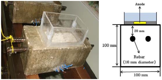
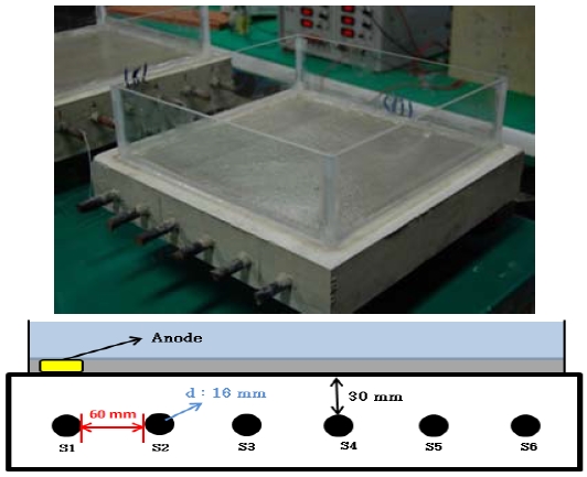
The specimen was cured for 28 days in air, and then removed from the mold. The mixed design of the specimens is given in Table 1. The rebar used was KS D16 (ASTM #5). Each beam-type specimen included 35 cm × 2 pieces of the rebar. The specimen was made following the ASTM G109 format (H: 10 cm, W: 10 cm, L: 25 cm) [11]. Figure 1 shows the beam-type specimen installed on the upper part of a water tank after removing the mold. The water tank was filled with 3% salt water, which was melted with salt in tap water, up to a height of 5 cm above the specimen, and the water was changed every week. Each slab-type specimen included 70 cm × 6 pieces of the rebar placed 6 cm apart. The size of each slab-type specimen was as follows: H: 7 cm, W: 40 cm, L: 40 cm.
Figure 2 shows the slab-type specimen installed on the upper part of a water tank after removing the mold.
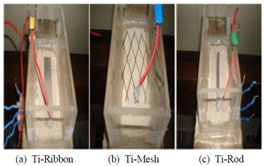
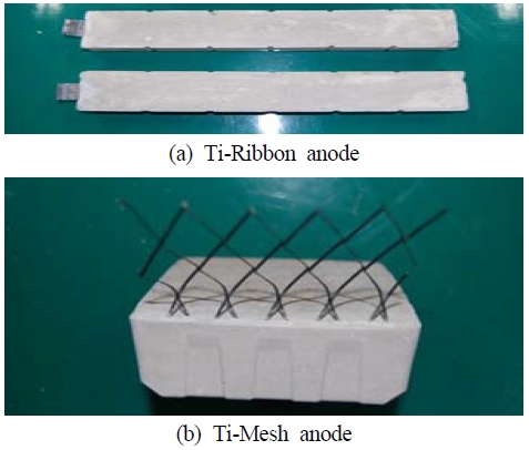
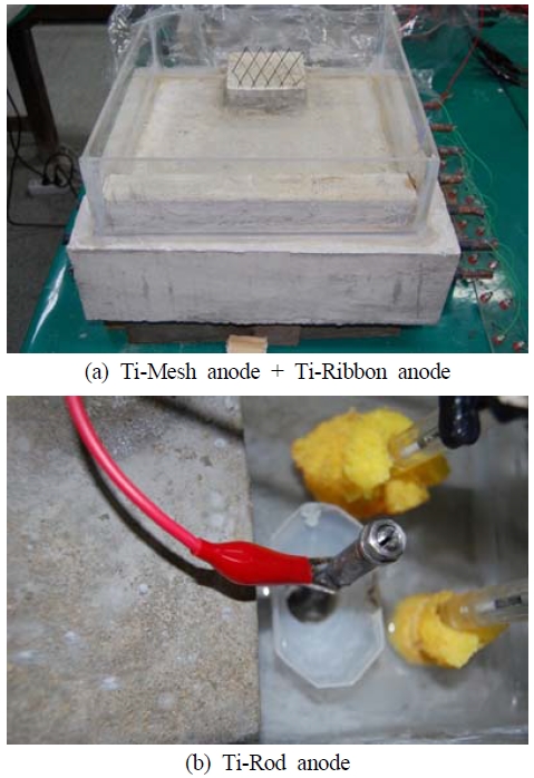
Figure 3 shows the installation of the three types of anodes for the beam-type concrete specimens. The sizes of the insoluble anodes were as follows: Ti-Ribbon: 10.0 cm × 2.0 cm, Ti-Rod: 9.0 cm × 10 Ø, Ti-Mesh: 9.0 cm × 6.5 cm. Figure 4 shows two types of anodes (Ti-Ribbon: 30.0 cm × 2.0 cm, Ti-Mesh: 10.0 cm × 10.0 cm) that were grouted by mortar for application in cathodic protection.
Figure 5 (a) shows the preparation of grouting by mortar above the slab-type specimen. The Ti-Ribbon anodes were installed on top of the first rebar parallel to it, and the Ti-Mesh anodes were installed on top of the fifth and sixth rebars. Figure 5 (b) shows the 20 mm hole made between the fifth and sixth rebars with the Ti-Rod (9.0 cm × 10 Ø) inserted into it, after which grouting with mortar was carried out. Both sides of the beam-type and slab-type specimens were drilled to the ends of the rebar and screws were used to fix the wires for measuring the potential and connecting with the cathodic protection system. The anode was connected to each end by wires and soldered to minimize the electrical contact resistance. The connection area was sealed with epoxy to prevent the flow of leakage current from the connection of cathodic protection current. The outer sides of the specimens, except the water tank, were coated with enamel to prevent evaporation and absorb water only from below.
2.2 Experimental method
The potential was measured by a silver-silver chloride reference electrode (SSCE). A CR-1212 multichannel power supply unit from CorRel Technology Inc. was used [12] to maintain the protection potential.
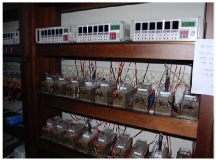
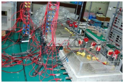
Figure 6 and Figure 7 illustrate the cathodic protection system with the power supply unit and connection between the rebars in the specimen, anode, and reference electrode. Six SSCEs were clamped to the upper part of each rebar in the specimen. To minimize the resistivity of the concrete between the concrete surface and reference electrode, a porous sponge was applied to the end of the reference electrode. In the case of the beam-type specimen, the protection potential was based on -900 mV/SSCE for cathodic protection, whereas in the case of the slab-type specimen, it was based on -600 mv/SSCE. The values of the potential for cathodic protection of each type of specimen were determined to prevent excessive depolarization, excluding the IR drop. While measuring the potential of a specimen exposed to air, a sponge was attached to the end of the reference electrode to provide an electrolytic path between the specimen and reference electrode. While measuring the potential of a specimen with sea water or tap water in the water tank, the reference electrode was soaked in the water. The protection potentials and depolarization of the types of anodes and exposed environment of the specimens were compared. The measurements were made automatically and at intervals of 1 min and all the data were monitored in real time and stored automatically on the computer by communication cables. In the case of the slab-type specimen, to investigate the dependence of the protection effect on the arrangement of the anodes, we conducted complex experiments such as using only the Ti-Ribbon anode, Ti-Ribbon together with Ti-Mesh anode, and Ti-Ribbon with Ti-rod anode and compared the protection characteristics by measuring the protection potentials and depolarization of each of the six rebars [13].
3. Experimental Results
3.1 Test results of beam-type specimens
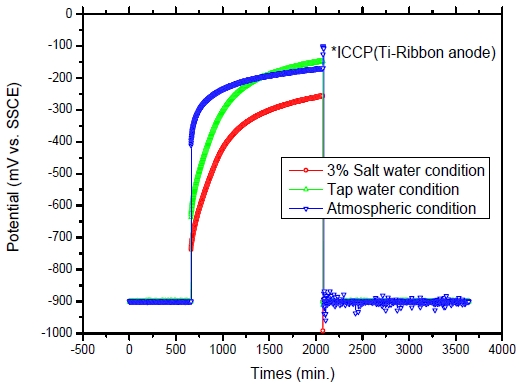
Figure 8, Figure 9 and Figure 10 show the depolarization behavior as a function of time, after switching off the power supply of the ICCP system in the beam-type specimens. Figure 8 presents the variation in potential of the beam-type specimens with the Ti-Ribbon anode, Figure 9 shows that with the Ti-Rod anode, and Figure 10 indicates that with the Ti-Mesh anode.
Variation in potential of beam-type specimen with Ti-Ribbon anode during an instant-off measurement of ohmic interference
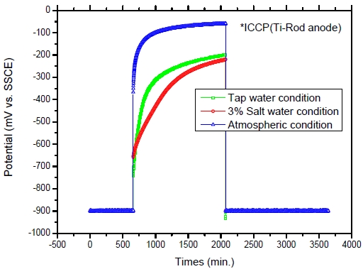
Variation in potential of beam-type specimen with Ti-Rod anode during an instant-off measurement of ohmic interference
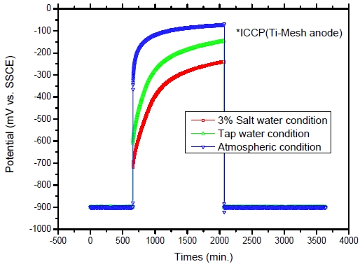
Variation in potential of beam-type specimen with Ti-Mesh anode during an instant-off measurement of ohmic interference
The deviation in the cathodic protection potential of the beam-type specimens with the three types of anode was measured when exposed to different conditions of corrosion.
The ohmic resistance measured instantly after switching off the power supply of the ICCP system was highest in the specimen exposed to atmospheric conditions, decreased as highly corrosive environments, and that exposed to 3 % salt water conditions was the lowest; however, the degree of depolarization, excluding ohmic resistance, was approximately 490–500 mV in 3 % salt water conditions, 450–490 mV in tap water conditions, 210–220 mV in atmospheric conditions, i.e., it increased in a highly corrosive environment.
As shown by these results, the polarization of the rebar in the beam-type specimen in atmospheric conditions progressed a little due to the high resistivity of concrete.
Results in different corrosive conditions for different types of insoluble anodes were obtained in the experiments. It was confirmed that a similar cathodic protection effect in reinforced concrete environment was shown by using any type of anode in the experiment. It was found that the results satisfied the standard of cathodic protection potential by NACE (100 mV depolarization criteria, except for IR drop) depending on the corrosive conditions and types of anodes used in the ICCP system [14].
Consequently, any method of installation of the anode in the ICCP system protects the reinforced concrete structure appropriately.
3.2 Test results of slab-type specimens
Figure 11 shows the results of variation in the cathodic protection potential at a setting of -600 mV/SSCE in constant potential mode of the CR-1212 power supply unit.
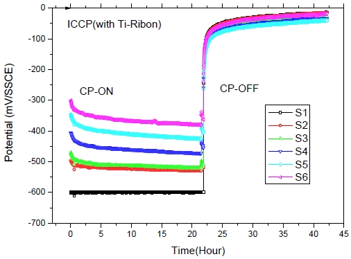
Variation in potential of slab-type specimen with Ti-Ribbon anode during an instant-off measurement of ohmic interference in 3% salt water condition
An insoluble Ti-Ribbon anode was installed on the rebar S1 at the side of the specimen, and 6 reference electrodes of silver/silver chloride were fixed on the surface of the specimen directly above the rebar.
The potential of rebar S1 was maintained at -600 mV/SSCE at the beginning of the measurement due to the vicinal distance of the anode after applying the ICCP system. The cathodic protection potentials of rebars S2 and S3, which were near S1, were approximately -520 mV/SSCE, that of S4 was -470 mV/SSCE, that of S5 was -420 mV/SSCE, and that of S6 indicated -370 mV/SSCE. The potentials of the rebars gradually shifted by 50 mV as a function of 6 cm distance from the anode to the rebar, and the degree of depolarization after switching off the power supply also indicated a gradual decrease as the distance from the anode to the rebar increased.
The cathodic protection potential showed an improvement due to addition of the Ti-Rod anode on the S6 rebar of the specimen as shown in Figure 12.
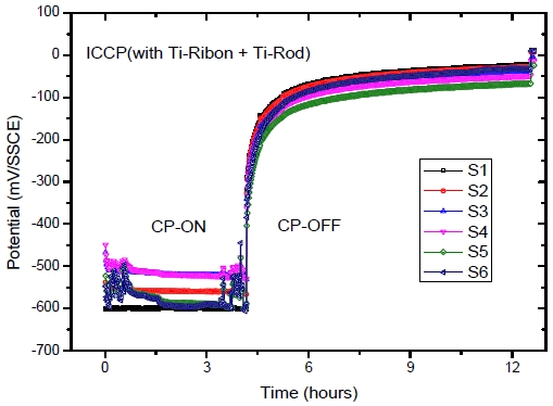
Variation in potential of slab-type specimen with Ti-Ribbon together with Ti-Rod anode during an instant-off measurement of ohmic interference in 3% salt water condition
The cathodic protection potential of the slab-type specimen changed for the S4, S5, as well as S6 rebars and was low at -530 mV/SSCE, and the degree of depolarization indicated was above 500 mV, which signified a satisfactory condition of cathodic protection.
The behavior of the cathodic protection potential of the slab-type specimen with two types of anodes, Ti-Ribbon and Ti-Mesh, is depicted in Figure 13. The difference between the potentials was approximately 10–50 mV, and all the values ranged from -540 to -600 mV/SSCE. The degree of depolarization indicated was above 500 mV signifying a satisfactory condition of cathodic protection.
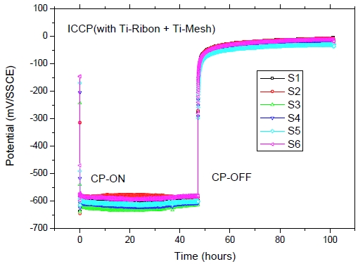
Variation in potential of slab-type specimen with Ti-Ribbon with Ti-Mesh anode during an instant-off measurement of ohmic interference in 3% salt water condition
From the experiment, it was confirmed that the use of different types of insoluble anodes in the ICCP system had no difference in the effect on the protection of reinforced concrete structure, and under-protected areas may occur as the distance from the anode to rebar increased, due to the resistivity of concrete.
Therefore, it should be protected thoroughly and homogeneously without any under-protected area with the distance between the anodes designed to be 30 cm as the maximum reachable space of cathodic protection current from the anode to the rebar was 15 cm as observed in the experiment. The anode that is structurally easy to install must be appropriately selected, if it is not possible to install a particular anode in a complex structure. It was found that the results satisfied the standard of cathodic protection potential by NACE. In addition, although anodes of different types were used for the reinforced concrete structure, similar cathodic protection effects were evident. Thus, if it is not possible to install a certain anode in the complicated concrete structure, an anode that can be installed easily can be used to carry out the corrosion protection suitably.
4. Conclusions
The results of the experiments on the cathodic protection effects to confirm the characteristics of the ICCP system according to the types and arrangements of anodes are as follows:
- (1) From the cathodic protection test of the beam-type specimens, it was confirmed that the ohmic resistance of the specimen exposed to atmospheric conditions was the highest and that of the specimens exposed to 3% salt water conditions was the lowest; however, the degree of depolarization, excluding ohmic resistance, increased in a highly corrosive environment.
- (2) From the cathodic protection test of the slab-type specimens, the cathodic protection potential increased as the distance from the rebar to anode increased; the increase was by 50 mV for a distance of 6 cm and the degree of depolarization, excluding ohmic resistance, decreased as the distance from the rebar to anode increased.
- (3) From the cathodic protection test of the beam-type and slab-type specimens, it was confirmed that the effect of cathodic protection had no relation with the types of ICCP anodes. It should be protected thoroughly and homogeneously without any under-protected area with the distance between the anodes designed to be 30 cm as the maximum reachable space of cathodic protection current from the anode to the rebar was 15 cm as observed in the experiment.
Author Contributions
Conceptualization, J. A. Jeong and M. Kim; Methodology, J. A. Jeong; Software, J. A. Jeong; Validation, J. A. Jeong and M. Kim; Formal Analysis, J. A. Jeong; Investigation, J. A. Jeong; Resources, J. A. Jeong; Data Curation, J. A. Jeong; Writing-Original Draft Preparation, J. A. Jeong; Writing-Review & Editing, M. Kim; Visualization, J. A. Jeong; Supervision, M. Kim; Project Administration, M. Kim; Funding Acquisition, M. Kim.
References
-
P. V. Bahekar, and S. S. Gadve, “Impressed current cathodic protection of rebar in concrete using Carbon FRP laminate”, Construction and Building Materials, 156, p242-251, (2017).
[https://doi.org/10.1016/j.conbuildmat.2017.08.145]

-
M. S. Anwar, B. Sujitha, and R. Vedalakshmi, “Light-weight cementitious conductive anode for impressed current cathodic protection of steel reinforced concrete application”, Construction and Building Materials, 71, p167-180, (2014).
[https://doi.org/10.1016/j.conbuildmat.2014.08.032]

-
G. Qiao, B. Guo, J. Ou, F. Xu, and Z. Li, “Numerical optimization of an impressed current cathodic protection system for reinforced concrete structures”, Construction and Building Materials, 119, p260-267, (2016).
[https://doi.org/10.1016/j.conbuildmat.2016.05.012]

-
J. A. Jeong, Y. K. Choo, C. K. Jin, and K. W. Park, “Numerical analysis results of the cathodic protection for the underground steel pipe by anode installation method”, Journal of the Korean Society of Marine Engineering, 38(10), p1212-1216, (2014).
[https://doi.org/10.5916/jkosme.2014.38.10.1212]

-
X. Xi, and S. Yang, “Time to surface cracking and crack width of reinforced concrete structures under corrosion of multiple rebars”, Construction and Building Materials, 155, p114-125, (2017).
[https://doi.org/10.1016/j.conbuildmat.2017.08.051]

-
J. A Jeong, M. S Kim, S. D Yang, C. H Hong, N. K Lee, and D. H Lee, “Study of the electrochemical polarization test of carbon steel in natural seawater”, Journal of the Korean Society of Marine Engineering, 42(4), p274-279, (2018), (in Korean).
[https://doi.org/10.5916/jkosme.2018.42.4.274]

- M. C. Garcia-Alonso, J. A. Gonzalez, J. Miranda, M. L. Escudero, M. J. Correia, M. Salta, and A. Bennari, “Corrosion behaviour of innovative stainless steels in mortar”, Cement and Concrete Research, 37(11), p1562-1569, (2007).
-
S. H. Xing, Y. Li, H. Q. Song, Y. G. Yan, and M. X. Sun, “Optimization the quantity, locations and output currents of anodes to improve cathodic protection effect of semi-submersible crane vessel”, Ocean Engineering, 113, p144-150, (2016).
[https://doi.org/10.1016/j.oceaneng.2015.12.047]

-
K. Wilson, M. Jawed, and V. Ngala, “The selection and use of cathodic protection systems for the repair of reinforced concrete structures”, Construction and Building Materials, 39, p19-25, (2013).
[https://doi.org/10.1016/j.conbuildmat.2012.05.037]

-
J. A. Jeong, M. S Kim, S. D. Yang, C. H. Hong, N. K. Lee, and D. H. Lee, “Cathodic protection using insoluble anodes by delivering protection currents to the inner surfaces of carbon steel seawater pipes”, Journal of the Korean Society of Marine Engineering, 42(4), p280-286, (2018), (in Korean).
[https://doi.org/10.5916/jkosme.2018.42.4.280]

-
E. Redaelli, F. Lollini, and L. Bertolini, “Throwing power of localized anodes for the cathodic protection of slender carbonated concrete elements in atmospheric conditions”, Construction and Building Materials, 39, p95-104, (2013).
[https://doi.org/10.1016/j.conbuildmat.2012.05.014]

-
J. Xu, and W. Yao, “Current distribution in reinforced concrete cathodic protection system with conductive mortar overlay anode”, Construction and Building Materials, 23, p2220-2226, (2009).
[https://doi.org/10.1016/j.conbuildmat.2008.12.002]

-
L. Bertolini, and E. Redaelli, “Throwing power of cathodic prevention applied by means of sacrificial anodes to partially submerged marine reinforced concrete piles : Results of numerical simulations”, Corrosion Science, 51, p2218-2230, (2009).
[https://doi.org/10.1016/j.corsci.2009.06.012]

-
C. Christodoulou, G. Glass, J. Webb, S. Austin, and C. Goodier, “Assessing the long term benefits of impressed current cathodic protection”, Corrosion Science, 52(8), p2671-2679, (2010).
[https://doi.org/10.1016/j.corsci.2010.04.018]


