2.2 L 직접분사 디젤 엔진에서 LNT 흡장률이 NOx 정화 효율에 미치는 영향
Copyright © The Korean Society of Marine Engineering
This is an Open Access article distributed under the terms of the Creative Commons Attribution Non-Commercial License (http://creativecommons.org/licenses/by-nc/3.0), which permits unrestricted non-commercial use, distribution, and reproduction in any medium, provided the original work is properly cited.
초록
디젤엔진은 가솔린엔진 대비 우수한 열효율 및 적은 CO2 배출과 더불어 우수한 토크 성능을 지닌다. 그러나 디젤엔진은 국부적인 고온 반응에 의해 발생하는 질소산화물(NOx) 및 확산연소에 의한 입자상물질의 배출이 높다. 이러한 NOx배출 저감을 위하여 흡장형 NOx 촉매(lean NOx trap, LNT)는 실차 장착의 용이성으로 배기가스재순환 기술 및 선택적 환원 촉매와 같이 사용할 경우 디젤엔진의 NOx 저감 성능을 극대화할 수 있다. 본 연구에서는 2.2 L 직접분사 커먼레일 디젤 엔진에서 NOx 흡장률에 따라 재생을 실시하여 LNT 촉매의 NOx 정화 효율을 분석하였다. LNT 재생 시의 촉매 전단 공기과잉률은 0.92 ~ 0.97의 범위를 갖으며, CO 농도는 약 1.6 ~ 2.6 %, O2 농도는 1.1 ~ 1.4 % 수준이었다. 엔진 운전 조건에 관계없이 NOx 흡장률이 높을수록 NOx 정화 효율이 감소하였다. 또한 NOx 흡장률 50 % 이하로 흡장 후 재생 하였을 때 운전조건에 관계없이 NOx 전환 효율은 60 % 이상이었다. 흡장률이 낮은 영역에서의 촉매 재생은 연료소모율이 증가하므로, 연료소모율의 최소화 및 NOx 정화 효율의 극대화를 동시에 고려하여 LNT 재생제어를 실시하여야한다.
Abstract
Diesel engines have higher thermal efficiency and lower CO2 emissions than gasoline engines, as well excellent low-to-medium speed torque characteristics. However, diesel engines produce higher levels of nitrogen oxides owing to the local high temperature reactions and the higher amount of particulate matter produced by diffusive combustion. To reduce NOx emissions, a lean NOx trap (LNT) maximizes its effectiveness to minimize NOx emissions from the diesel engine when used with exhaust gas recirculation and selective catalytic reaction technologies owing to its ease to mount on the actual vehicle. In this study, NOx conversion efficiency of an LNT catalyst was analyzed via the LNT regeneration according to the NOx adsorption fraction in a 2.2 L direct-injection common-rail diesel engine. The lambda values of the exhaust gas during the regeneration of the LNT were within the range of 0.92 ~ 0.97, the CO concentration was approximately 1.6 ~ 2.6%, and the O2 concentration was approximately 1.1 ~ 1.4%. Regardless of the engine operating conditions, the NOx conversion efficiency decreased as the NOx adsorption fraction increased. When the LNT was regenerated at less than 50% of the NOx adsorption fraction, the NOx conversion efficiency was observed to be more than 60%, regardless of the operating conditions. Because the LNT regeneration at the lower NOx adsorption fraction leads to an increase in the fuel consumption, the LNT regeneration strategy should consider the simultaneous minimization of the fuel consumption rate and the maximization of the NOx conversion efficiency.
Keywords:
Diesel engine, Lean NOx trap, LNT regeneration, Adsorption fraction, NOx키워드:
디젤엔진, 흡장형 NOx 촉매, LNT 재생, 흡장률, 질소산화물1. 서 론
디젤엔진은 가솔린엔진보다 높은 압축비에서 운전되어 높은 열효율과 낮은 연료 소비율을 가지므로 연비 감소 및 CO2 배출량이 적으며, 중저속 토크 특성이 우수하다[1]. 그러나 디젤엔진은 국부적인 고온 반응에 의해 발생하는 질소산화물(nitrogen oxides, NOx)과 확산연소에 의해 발생하는 입자상물질(particulate matter, PM) 발생이 상대적으로 높다[1]. NOx와 PM은 인체와 환경에 매우 유해한 물질로써 이를 저감하기 위한 다양한 기술이 연구 개발되고 있다. 그 중에서 디젤엔진의 전자에어 및 연료분사 압력 증가를 통한 미립화(atomization), 배기가스재순환(exhaust gas recirculation) 등의 전처리 기술이 있다[2].
전처리 기술을 적용하여도 배출되는 PM 및 NOx는 후처리를 통하여 제거된다. 후처리 기술로서 PM을 제거를 위하여 PM을 필터로 포집한 후 포집한 PM을 주기적으로 산화시키는 매연여과장치(diesel particulate filter, DPF)가 있다[3][4]. NOx 저감을 위한 후처리 기술로는 엔진에서 배출되는 NOx를 저감하기위하여 해당 촉매에 유레아(urea)를 분사하여 열분해에 의한 암모니아(NH3)를 생성시켜, 이를 NOx 저감을 위한 환원제로 사용하는 선택적 환원촉매(selective catalytic reaction, SCR) 기술이 있다[5]. 또한 NOx 저감을 위한 후처리 기술에는 촉매에 NOx를 흡장한 후 엔진 연료 분사시기 제어를 통한 실런더 내 후 분사 방법(in-cylinder post fuel injection)을 이용하여 CO, H2, THC 등을 다량으로 발생시켜, NOx를 환원시켜 재생하는 흡장형 NOx 저감 촉매(lean NOx trap, LNT) 기술이 있다[6]-[8]. 실린더 내 후 분사 방법은 기존에 장착 되어있는 연료 인젝터를 사용하여 팽창 행정 시, 추가적으로 실린더 내부에 연료를 분사하여 환원제를 얻는다[9][10]. 실제 엔진에 LNT 촉매를 적용하기 위하여 촉매 재생 제어 및 재생을 위한 조건에 관련된 연구가 필요하다[11].
본 논문에서는 2.2 L 직접분사 커먼레일 디젤엔진을 이용하고, 실린더 내 후 분사 방법을 사용하여 LNT의 흡장률에 따른 NOx 정화 성능을 분석하였다. LNT 촉매의 NOx 정화 효율 분석을 위하여 환원 환경 조성을 위한 후 분사시간, 후 분사 시기, 후 분사 연료량 등은 각 운전 조건에 맞게 제어하였다. 각 실험 조건에서 NOx의 최대 흡장량을 기준으로 25, 50, 75, 100 % 흡장되었을 때 재생을 실시하여 LNT 촉매의 NOx 정화 효율을 비교하여 LNT 재생제어를 위한 기초 자료로 제시하고자 한다.
2. 실험 장치 및 방법
2.1 실험 장치
본 연구는 실린더 내 후 분사 방법을 이용하여 LNT 촉매의 NOx 정화 성능 분석을 진행하였으며, 실험을 위한 엔진은 2.2 L 커먼레일 디젤 엔진으로 압축비는 16:1이다. 사용된 엔진의 자세한 제원은 Table 1에 나타내었다.
본 연구에 사용된 LNT 촉매는 E&D사에서 제공한 2.5 L 촉매를 장착하여 실험하였다. LNT 촉매는 Ba을 통하여 NOx가 흡장되며, 환원제 공급에 의하여 탈착될 때 Pt 및 Rh에 의하여 NOx가 N2로 환원된다. 사용된 LNT 촉매의 자세한 제원은 Table 2에 나타내었다.
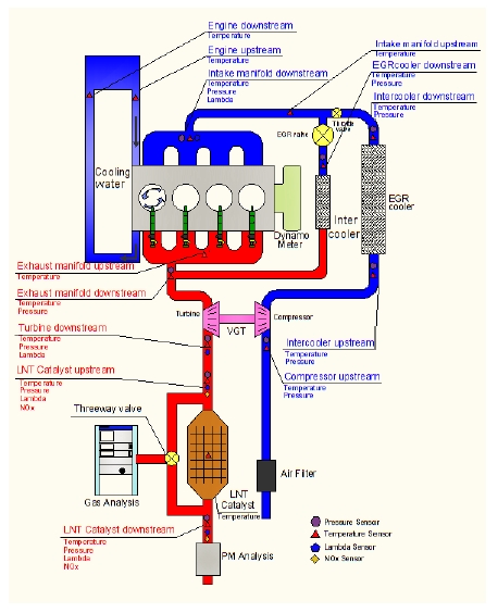
디젤 엔진에서 배출되는 배기가스를 측정하기 위해 Horiba 사의 MEXA –1600DEGR 배기가스 분석기를 사용하였다. 이를 이용하여 실험엔진에서 배출되어진 CO, THC, NOx, O2, CO2를 측정하였다. 또한 LNT 촉매 전/후단의 NOx 농도 거동의 실시간 비교를 위하여 Continental사의 상용 NOx 센서를 사용하였다. 본 실험을 위한 전체적인 개략도는 Figure 1과 같다.
2.2 실험 방법
LNT 촉매의 환원 환경 조성을 위한 방법으로는 ECU 제어 프로그램인 INCA 소프트웨어를 이용하였으며, 이를 이용하여 엔진의 흡기스로틀밸브(intake throttle valve), 배기재순환밸브(exhaust gas recycle valve), 후 분사 시기(post injection timing), 후 분사 연료량(post injection fuel quantity) 등의 변수를 제어하였다. 각 운전 영역에서 엔진 변수의 제어를 통해 LNT 촉매의 환원 환경을 최적화 하여 실험을 진행하였다.
LNT 촉매 실험에서 적용되는 중요한 변수는 LNT 촉매 전/후단의 배기가스 공기과잉률(lambda)와 온도, 공간속도(space velocity, SV) 등이 있으며, 공기과잉률은 공기과잉률센서(LSU4.9)를 사용하여 측정하였다. 또한 공기과잉률센서를 이용하여 배기가스 공연비(air to fuel ratio, AFR) 및 연료 분사량을 계산하였다. SV는 AFR에 의해 계산된 연료 분사량과 엔진에서 측정된 흡입공기유량을 적용하고, 이상기체 상태방정식을 표준 조건에 대해 적용하여 계산하였다. LNT 촉매의 전/후단과 촉매 내부의 온도는 K-type 온도센서를 설치하여 측정하였다. 엔진과 LNT 촉매의 데이터 획득에는 CANape(Vector사) 소프트웨어를 이용하였다.
3. 실험 결과 및 고찰
3.1 실험 운전 영역에서의 LNT 재생
본 실험을 위한 실험영역은 LNT 촉매의 온도와 SV를 고려하여 5개의 엔진 운전 영역을 선정하였다. 각 실험 영역에서 희박연소 구간에서의 실험 조건들을 Table 3에 나타내었다. 선정된 각 운전 영역에 대하여 LNT 최대 NOx 흡장량 대비 25, 50, 75, 100 % 흡장 후 LNT 재생을 실시하여 LNT 촉매의 NOx 정화 효율을 비교하였다. 여기서, 각 운전 영역에서 LNT 최대 NOx 흡장량 대비 현재의 흡장량을 흡장률로 정의한다. 그리고 NOx 정화 효율(conversion efficiency)은 LNT 촉매 전단에서 측정한 NOx 값과 촉매 후단에서 측정한 NOx 값의 차이를 촉매 전단 NOx 값으로 표준화하고 이를 시간에 대하여 적분하여 정의한다.
정상연소(normal combustion)에서는 디젤연소 특성상 희박연소(lean combustion)를 하며, LNT 재생 시에는 환원제 생성 및 NOx 정화 효율 향상을 위하여 공기과잉률 1이하로 농후연소(rich combustion or regeneration)를 실시하였다. 농후연소 구간에서의 공간속도는 LNT 촉매 재생 시 촉매 내 환원 성능을 높여주기 위하여 희박연소 구간 보다 약 30 % 감소하였다. 재생 시의 LNT 전단의 농후 정도는 0.92 ~ 0.97의 범위를 갖도록 후분사 시기와 후분사 연료량 제어를 실시하였다. 각각의 구간에 대한 공간속도와 공기과잉률을 Figure 2와 Figure 3에 나타내었다. LNT 촉매 재생 시간은 LNT 촉매의 완전한 환원을 위하여 전 실험영역에서 45 초로 동일하게 진행하였다.
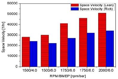
Various space velocity according to engine operating conditions for lean combustion phase and rich phase (regeneration phase)
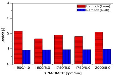
Various exhaust lambda according to engine operating conditions for lean combustion phase and rich phase (regeneration phase)
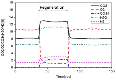
LNT 촉매 전단에서 배기가스 분석기를 통해 측정된 농후운전 영역에서의 CO 농도는 약 1.6 ~ 2.6 %의 범위로 나타났고, O2 농도는 1.1 ~ 1.4 %, CO2 농도는 12.5 ~ 13.3 %의 범위를 갖는다. THC 농도의 경우 2000 rpm 6 bar BMEP에서 약 2200 ppmC 수준, 이 영역을 제외한 나머지 실험 영역에서는 배기가스 분석기의 THC 측정 최대치인 5000 ppmC를 초과하였다. Figure 4는 1500 rpm 6 bar BMEP에 대하여 재생구간에서의 CO2, O2, CO, H2O, H2의 거동이다. 여기서, H2O 및 H2는 CO, CO2 농도로부터 계산된 값이다[12].
3.2 LNT 흡장률에 따른 NOx 정화 효율 비교
본 실험은 LNT 흡장률 25, 50, 75, 100 %에서 LNT 재생을 실시하여 NOx 정화 효율을 계산하여 LNT 촉매의 성능을 비교하였다. Figure 5 ~ Figure 8은 각각 1500 rpm 6 bar BMEP 조건에서 LNT 흡장률 25, 50, 75, 100 %에서 재생을 실시한 그래프이다. 재생구간 진입 시 첫 번째 NOx peak 현상이 목격되고 이후 2차 peak 현상이 목격된다. 이는 재생 시 LNT 내부에 흡장되었던 NOx가 순간적으로 배출되는 것으로 NOx 탈착반응과 환원반응의 속도에 의하여 peak의 크기가 결정된다. NOx 정화 효율의 계산은 NOx 방출량이 최저인 구간에서 부터 재생 완료 후 흡장이 다시 시작될 때까지의 촉매 전/후방 NOx 농도를 측정하여 계산하였다.
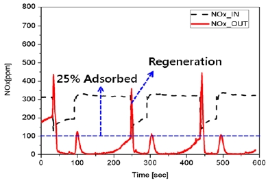
Catalyst-in (NOx_IN) and catalyst-out (NOx_OUT) NOx emissions at the adsorption fraction of 25 %: 1500 rpm 6 bar BMEP
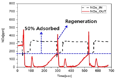
Catalyst-in (NOx_IN) and catalyst-out (NOx_OUT) NOx emissions at the adsorption fraction of 50 %: 1500 rpm 6 bar BMEP
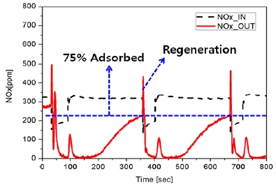
Catalyst-in (NOx_IN) and catalyst-out (NOx_OUT) NOx emissions at the adsorption fraction of 75 %: 1500 rpm 6 bar BMEP
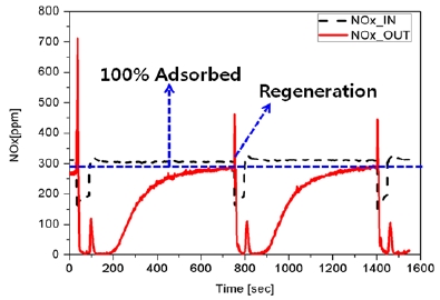
Catalyst-in (NOx_IN) and catalyst-out (NOx_OUT) NOx emissions at the adsorption fraction of 100 %: 1500 rpm 6 bar BMEP
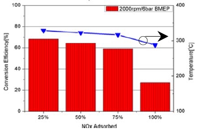
LNT 촉매 성능 실험을 통한 NOx 정화 효율을 각 운전영역에서 흡장률에 따라 구분하여 비교하였다. Figure 9 ~ Figure 13은 5개 엔진 운전영역에서 흡장률에 따른 NOx 정화 효율과 LNT 촉매 전단 온도를 나타내는 그래프이다. 본 실험의 재생 조건 및 촉매성능을 기준으로 각각의 엔진운전 영역에서 흡장률이 높을수록 NOx 정화 효율이 전체적으로 감소함을 알 수 있다. 이는 해당 공간속도 및 촉매 온도에서 LNT 촉매에 흡장된 NOx의 탈착 및 환원속도 그리고, 환원제의 량에 의하여 영향을 받으며, 특히 흡장률이 높을 경우 탈착 및 환원되어져야할 NOx 량이 증대하므로 정화 효율이 감소하는 것으로 판단된다. NOx 흡장률에 따른 결과를 분석할 경우, 25 % 흡장 후 재생 하였을 때, 각 운전영역에서의 NOx 정화 효율은 68 ~ 87 %의 수준을 나타냈으며, 50 % 흡장 후 재생을 실시한 경우 64 ~ 81 % 수준, 75 % 흡장 후 재생 시 44 ~ 66 % 수준, 100 % 흡장 후 재생 시 25 ~ 38 % 수준의 성능을 보였다. 즉, NOx 흡장률 50 % 이하로 흡장 후 재생 하였을 때 운전조건에 관계없이 NOx 전환 효율은 60 %이상으로 나타났다. 흡장률이 낮은 영역에서 촉매 재생시 NOx 정화 효율은 증가하나 잦은 재생으로 인하여 상대적으로 연료소모율이 증가하므로, 연료소모율의 최소화 및 NOx 정화 효율의 극대화를 동시에 고려하여 LNT 재생을 실시하여야한다.
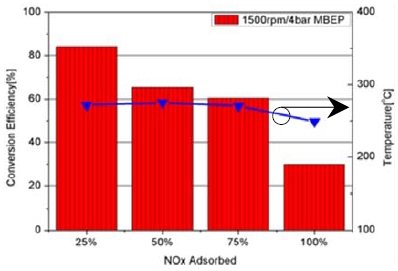
NOx conversion efficiency and exhaust gas temperature at the inlet of the LNT catalyst with regards to NOx adsorption fraction at 1500 rpm 4 bar BMEP
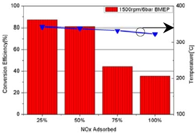
NOx conversion efficiency and exhaust gas temperature at the inlet of the LNT catalyst with regards to NOx adsorption fraction at 1500 rpm 6 bar BMEP
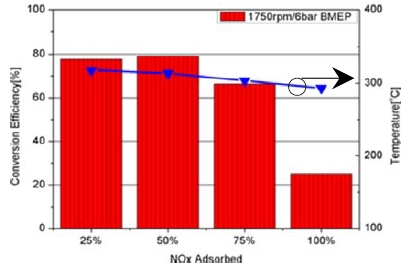
NOx conversion efficiency and exhaust gas temperature at the inlet of the LNT catalyst with regards to NOx adsorption fraction at 1750 rpm 6 bar BMEP
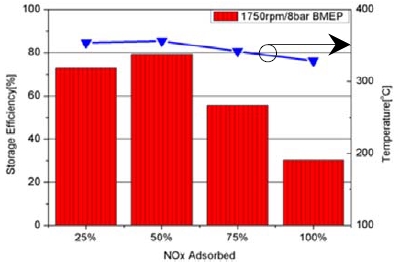
NOx conversion efficiency and exhaust gas temperature at the inlet of the LNT catalyst with regards to NOx adsorption fraction at 1750 rpm 8 bar BMEP
4. 결 론
본 실험에서는 2.2L 직접분사 커먼레일 디젤 엔진을 이용하여 NOx 흡장률에 따라 LNT 재생을 실시하여 LNT 촉매의 NOx 정화 효율을 분석하였다. LNT 재생 시의 촉매 전단 공기과잉률은 0.92 ~ 0.97의 범위를 갖으며, CO 농도는 약 1.6 ~ 2.6 %, O2 농도는 1.1 ~ 1.4 % 수준으로, 다음과 같은 결론을 얻었다.
- (1) 엔진 운전 조건에 관계없이 NOx 흡장률이 높을수록 NOx 정화 효율이 감소하였으며, 이는 흡장률이 높을 때 재생할 경우 탈착 및 환원되어져야할 NOx 량이 상대적으로 증대하므로 정화 효율이 감소하는 것으로 판단된다.
- (2) NOx 저감을 위하여 LNT 촉매 적용시 NOx 흡장률 50 % 이하로 흡장 후 재생 하였을 때 운전조건에 관계없이 NOx 전환 효율은 60 % 이상이었다.
- (3) 흡장률이 낮은 영역에서 촉매 재생은 NOx 정화 효율은 증가하나 잦은 재생으로 인하여 상대적으로 연료소모율이 증가하므로, 연료소모율의 최소화 및 NOx 정화 효율의 극대화를 동시에 고려하여 LNT 재생을 실시하여야한다.
Acknowledgments
이 연구는 지식경제부 산업원천기술개발 사업의 일환으로 수행된 연구결과(No. 10039673)로 이에 감사드립니다.
Author Contributions
The following statements should be used “Conceptualization, B. Chun and M. Han; Methodology, B. Chun and M. Han; Software, B. Chun; Validation, B. Chun and M. Han; Formal Analysis, B. Chun; Investigation, B. Chun and M. Han; Resources, B. Chun; Data Curation, B. Chun; Writing—Original Draft Preparation, B. Chun; Writing—Review & Editing, M. Han; Visualization, B. Chun; Supervision, M. Han; Project Administration, M. Han; Funding Acquisition, M. Han”.
References
- J. B. Heywood, Internal Combustion Engine Fundamentals, McGraw-Hill, (1988).
-
K. Song, “Effect of EGR on power and exhaust emissions in diesel engine”, Journal of the Korean Society of Marine Engineering, 39(9), p870-875, (2015), (in Korean).
[https://doi.org/10.5916/jkosme.2015.39.9.870]

-
M. Ootake, T. Kondou, M. Ikeda, M. Daigo, M. Nakano, J. Yokoyama, and M. Miura, “Development of diesel engine system with DPF for the european market”, SAE Technical Paper 2007-01-1061, (2007).
[https://doi.org/10.4271/2007-01-1061]

-
M. Lapuerta, J. J. Hernandez, and F. Oliva, “Strategies for active diesel particulate filter regeneration based on late injection and exhaust recirculation with different fuels”, International Journal of Engine Research, 15(2), p209-221, (2014).
[https://doi.org/10.1177/1468087412468584]

-
P. G. Blakeman, G. R. Chandler, G. A. John, and A. J. J. Wilkins, “Investigations into NOx aftertreatment with urea-SCR for light-duty diesel vehicles”, SAE Technical Paper 2004-01-3624, (2004).
[https://doi.org/10.4271/2001-01-3624]

-
M. Ueda, A. Asamo, T. Kondo, Y. atanable, T. Fukuma, and Y. Harada, “A new optimizing technique of a diesel engine aftertreatment system using HC DeNOx catalyst”, JSAE Technical Paper 20034007, (2003).
[https://doi.org/10.1016/s0389-4304(02)00249-7]

- J. S. Han, J. M. Oh, K. H. Lee, and J. H. Lee, “A study on the conversion performance of lean NOx trap for a 4-stroke diesel engine”, Transactions of Korean Society of Automotive Engieers (KSAE), 19(2), p78-83, (2011), (in Korean).
-
J. Parks, B. West, M. Swartz, and S. Huff, “Characterization of lean NOx trap catalysts with in-cylinder regeneration strategies”, SAE Technical Paper 2008-01-0448, (2008).
[https://doi.org/10.4271/2008-01-0448]

-
A. Sperl, “The influence of post-injection strategies on the emissions of soot and particulate matter in heavy duty euro V diesel engine”, SAE Technical Paper 2011-36-0350, (2011).
[https://doi.org/10.4271/2011-36-0350]

-
H. Yun, and R. D. Reitz, “An experimental investigation on the effect of post-injection strategies on combustion and emissions in the low-temperature diesel combustion regime”, Journal of Engineering for Gas Turbines and Power, 129(1), p279-286, (2007).
[https://doi.org/10.1115/1.2180812]

-
H. Lee, M. Han, and M. Sunwoo, “Robust indicated mean effective pressure and combustion lambda feedback control for lean NOx trap regeneration in a 2.2L common rail direct injection diesel engine”, Journal of Engineering for Gas Turbines and Power, 137(8), p081504, (2015).
[https://doi.org/10.1115/1.4029479]

-
K. Ramanathan, and C. S. Sharma, “Kinetic parameters estimation for three way catalyst modeling”, Industrial Engineering Chemistry Research, 50(17), p9960-9979, (2011).
[https://doi.org/10.1021/ie200726j]


