A study on battery characteristics for electrical propulsion vessels according to charging current and harmonic discharging load
Copyright © The Korean Society of Marine Engineering
This is an Open Access article distributed under the terms of the Creative Commons Attribution Non-Commercial License (http://creativecommons.org/licenses/by-nc/3.0), which permits unrestricted non-commercial use, distribution, and reproduction in any medium, provided the original work is properly cited.
Abstract
The use of high energy density lithium batteries has increased for propulsion vessels. Methods for reducing their charging time have been widely studied. A very common method of rapidly charging a battery entails increasing the charging current. The power conversion system of electrically propelled ships comprises a converter and an inverter, operating via switching action. Thus, the output voltage and current often include harmonics. However, if the charging or discharging current of the battery includes harmonics or is too large, the life of the battery may be reduced. In this study, we investigate the aging characteristics of batteries according to the amount of charging current related to the discharging current with and without harmonics. The internal impedance of the battery is measured using electrochemical impedance spectroscopy to analyze battery aging.
Keywords:
Lithium battery, Harmonic, Electrochemical impedance spectroscopy, Battery aging1. Introduction
Rechargeable lithium batteries are widely used as backup electrical power ship propulsion, provided they are maintained in a waterproof, flame-retardant, and dustproof manner. These batteries have a higher charging capacity than lead-acid batteries (primary power), and it has a relatively longer life span with a low self-discharge rate. Lithium ship batteries use a power converter to drive high-voltage and high-power loads according to specifications applied to eco-friendly, self-propulsion ships [1][2].
The power conversion system connected to the battery comprises a converter and an inverter, and harmonics is included in the output voltage or current. This is caused by the switching action of the semiconductor. There are high-level inverters designed to reduce harmonics in inverters converting direct current (DC) to alternating current (AC). As the harmonic levels rise, more sinusoidal voltages are produced with stronger harmonic characteristics. When the input voltage is V, two voltage levels of 0 and VDC are generated in the two-level inverter, and three voltage levels of 0, 1/2VDC , VDC are generated in the three-level inverter. A voltage order of one cycle moves through 0, VDC , 0, -VDC , and 0 in the two-level inverter. It moves through 0, 1/2VDC ,, VDC , 1/2VDC , 0, -1/2VDC , -VDC , -1/2VDC , and 0 in the three-level inverter [3].
Depending on the inverter level, the harmonic characteristics of the load current changes, affecting battery life. A large-current battery with harmonics discharges faster than necessary [4]. The use of rapid charging methods have increased, more than doubling charging speeds while accelerating battery aging. Battery life can be estimated by measuring the battery’s internal resistance. Thus, it is necessary to periodically manage the battery condition [3].
In this research, we conduct fast-charging and rated-charging experiments for batteries with and without harmonics, and we analyze battery aging.
2. Equivalent circuit analysis
2.1 Parameter analysis
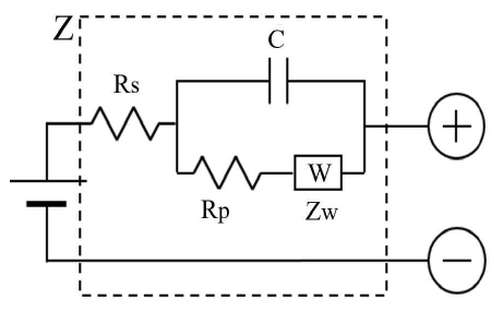
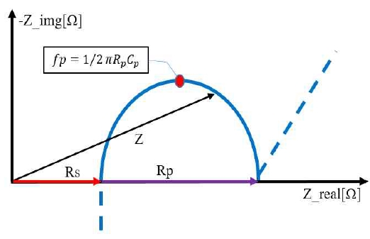
The electrochemical process inside a battery is represented by the simplified impedance model shown in Figure 1. Z represents the impedance of the battery and is divided by the real number R_real and the imaginary number R_imag in Figure 2. Rs is the resistance of the battery interior (electrode, electrolyte). Large voltage and current times dominate battery characteristics. This is also called AC resistance, measured at high frequencies. The Rs value increases as performance deteriorates because of battery aging. Therefore, it is common to measure the battery’s state-of-health (SoH). The relationship between Rs and SoH differs depending on the type and size of the battery. The method of continuously updating the correlation between Rs and SoH is applied while demonstrating evaluation criteria via preliminary examination of the same type of battery [5][6].
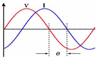
Rp represents the electrochemical reaction rate, and Cp represents the capacitor function of the electric double layer between the electrode and the electrolyte. Rp and Cp are criteria for indicating the state-of-charge (SoC) of the battery [7]. For a lithium battery, Rs is detected in the vicinity of 1 kHz. The relationship between the sinusoidal AC voltage and the response current is shown in Figure 3. The phase difference between battery current and voltage is denoted by θ, and the impedance relation is as follows:
| (1) |
2.2 C-rate
For a battery with a capacity of 1 Ah, the reference-1 C-rate (expressed as C) is 1 A, and the amount of current is the capacity of the cell. The lithium secondary battery can charge and discharge several times, and can have different energy storage states depending on charge and discharge methods [6].
2.3 SoH (State of health)
A battery stores and delivers electrical power via an electrochemical process. The SoH represents a battery’s usable life (%). Battery-aging and deterioration processes are important concerns. Deterioration is affected by chemical, external environment, and electrical characteristics. Thus, it is very difficult to accurately grasp the value of SoH. The maximum usable capacity of the battery is closely related to SoH, and if the battery is reduced to 80% of the maximum usable capacity, it is considered unusable. Furthermore, as the battery is repeatedly charged and discharged, performance is reduced and life span is shortened [5][8].
2.4 SoC (State of Charge)
Unlike conventional primary batteries, a lithium secondary battery can charge and discharge many times. Thus, they have a variety of energy storage states. Capacity is defined as the total charge amount when discharged at a constant current from fully charged (SoC = 100%) to empty (SoC = 0%) [5][6].
3. Experiment and discussion
3.1 Software
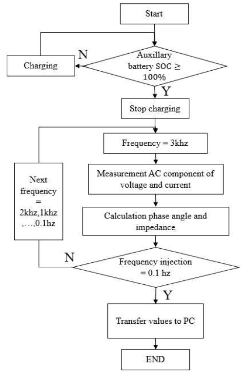
Figure 4 shows a flowchart for measuring the impedance of a microprocessor battery . If the SoC of the battery is 100 %, it is measured using the electrochemical impedance spectroscopy (EIS) technique. If conditions are not satisfied, charging is continued. Next, an initial frequency of 3 kHz is injected into the battery to measure the voltage and current. Then, the phase is obtained. Impedance can be obtained from Equation (1). Until the frequency reaches 0.1 Hz, the next frequency is continuously injected and proceeds in sequence. When the frequency reaches 0.1 Hz, it stops and transmits the impedance value to the PC. Then, a two-dimensional impedance mapping graph is constructed with R and X values.
3.2 Hardware
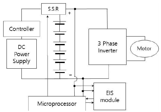
Figure 5 presents a block diagram for measuring the impedance of a battery with an EIS module according to the amount of current during charge and the presence of harmonics during discharging. Six lithium-polymer batteries were connected in series to produce 24-V DC. Charging was accomplished with a DC power supply, and the controller was adjusted for both rapid and rated currents. Using the 26-W inverter (24 V, 1 A, 3-phase) we produced a discharge both with and without harmonic wave via the electronic load. The microprocessor (Atmega128P) detected the voltage and charged when the SoC reached 0%, stopping at 100 %. After 50 cycles of charging and discharging, the impedance of the battery was measured using the EIS module.
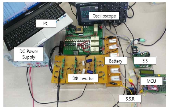
Figure 6 shows the experimental device. It comprises a microprocessor, an EIS module, two- and three-level inverters, and a power supply. Table 1 shows the specification of the lithium polymer battery used in the experiment.
First, the battery was charged to SoC 100 % , and the initial internal impedance of the battery was measured and discharged using the EIS module. When the SoC was 0 %, charging began until it reached 100%. Then, discharging was repeated, stopping when the temperature of the battery was 50 °C or greater or the battery voltage was 2.5 V or less. For rapid and rated charging experiment, the measures were divided into 1-h (1C) and 30-min (2C) charging sessions. The discharging load measured both with and without harmonics.
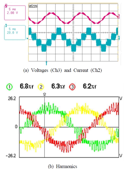
Figure 7 shows the voltage waveform and harmonics components of the 3-ɸ inverter. Figure 7 (a) shows the output voltage and current of the 3-phase inverter, measured with an oscilloscope. Figure 7 (b) shows the harmonics components of the 3-ɸ inverter, measured with a power-quality measuring instrument, resulting in 6.8 %, 6.3 %, and 6.2 %.
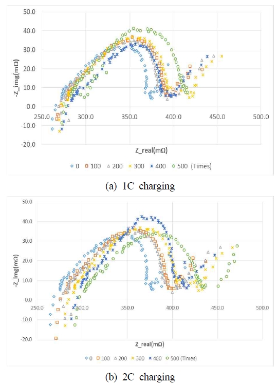
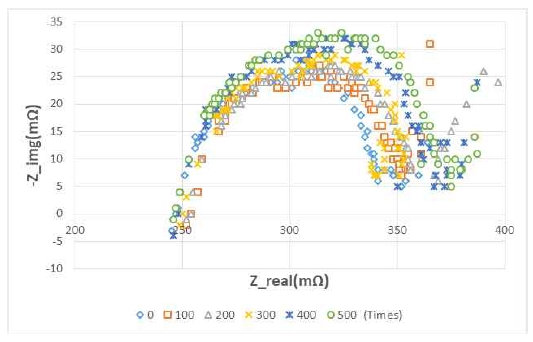
Figure 8 graphs the impedance measurement when harmonics are included. Impedance characteristics were measured through the EIS every 100 charge/discharge cycles at 1C and 2C. Figure 9 graphs the impedance without harmonics. Impedance characteristics were measured with the EIS every 100 charge/discharge cycles. The waveforms are pushed to the right as the number of charge/discharge cycles increase, and Rs gradually increases. Thus, aging is clearly affected by the number of charge/discharge cycles.
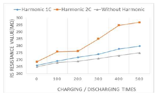
Figure 10 and Table 2 depict lifetime Rs at 1C and 2C. Harmonics are included with 2C, but 1C does not include harmonics. When harmonics were included, the initial value of Rs was 266 mΩ at 1C. However, Rs was measured as 279.8 mΩ after 500 charge/discharge cycles. With 2C, the initial value of Rs was 268.5 mΩ, The Rs value after the initial discharge was 296.8 mΩ. Without harmonics, it increased from 265 mΩ to 275 mΩ.
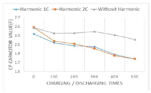
Figure 11 and Table 3 depict the capacity (Rp) at 1C and 2C with one level of harmonics and at 1C without harmonics. The initial values at 1C and 2C with harmonics were 2.335 F and 2.483 F, respectively. After 500 experiments, 1.781 F and 1.783 F were measured. When the harmonics were not included, it decreased from the initial 2.475 F to 2.213 F.
4. Conclusion
We conducted fast-charging and rated-charging experiments when the discharge current of a lithium-ion battery contained harmonics and when it did not. We analyzed battery aging, reaching the following conclusions.
- (1) The increase of Rs for estimating battery aging was 13.8 mΩ and 28.3 mΩ at 1C and 2C, respectively. Thus, rapid-charging decreases lifespan rapidly, compared to rated charging.
- (2) With rated charging, the increase of Rs was 10 mΩ and 13.8 mΩ, with and without discharging harmonics, respectively. Thus, we confirmed that, with more discharge current harmonics, aging proceeds more quickly.
- (3) The increase of Rp for estimating the battery charging state with discharging harmonics was 0.55 F and 0.701 at 1C and 2C, respectively. Rp was 0.262 F when the charging current was 1C only, without discharging current harmonics.
We confirmed that the battery capacity under rapid charging conditions was reduced more than the rated charge and that the more harmonics included in the discharge current, the more the battery capacity increased.
Acknowledgments
Following are results of a study on the “Leaders in INdustry-university Cooperation +” Project, supported by the Ministry of Education and National Research Foundation of Korea.
Author Contributions
The following statements should be used “Conceptualization, T. H. Song and S. G. Lee; Methodology, T. H. Song and H. S. Yang; Software, T. H. Song and H. S. Yang; Validation, T. H. Song and H. S. Yang; Investigation, T. H. Song and H. S. Yang; Resources, T. H. Song and Y. S. Kim; Data Curation, T. H. Song and H. S. Yang; Writing—Original Draft Preparation, T. H. Song; Writing—Review & Editing, T. H. Song and H. S. Yang; Supervision, S. G. Lee; Project Administration, T. H. Song and H. S. Yang; Funding Acquisition, T. H. Song.
References
- H. J. Kwon, A Study of Remote Management System of Lithium Ion Battery for Ship Based on BLE, M.S. Dissertation, Department of Electrical and Electronic Engineering, Graduate School of Korea Maritime and Ocean University, Korea, (2015), (in Korean).
- Research Center of Meritz, Reignition of Growth Engine with midium and large scale 2nd battery ESS, Nov.), (2011, (in Korean).
- M. J. Kim, BMS for Output Stabilization of Inverter Control System in Hybrid Electric Propulsion Ship, M.S. Dissertation, Department of Electrical and Electronic Engineering, Graduate School of Korea Maritime and Ocean University, Korea, (2018), (in Korean).
- H. S. Ma, Battery Management System with High-Reliability for Power Conversion System, M.S. Dissertation, Department of Electrical and Electronic Engineering, Graduate School of Korea Maritime University, Korea, (2017), (in Korean).
- J. L. Choi, Study on Electrochemical Impedance Spectroscopy Equipment for Checking State of Battery, M.S. Dissertation, Department of Electrical and Electronic Engineering, Graduate School of Korea Maritime and Ocean University, Korea, (2018), (in Korean).
-
T. H. Song, H. S. Yang, Y. S. Kim, and S. G. Lee, “Investigation of the lifespan characteristics of a rapid charge/discharge battery using the inverter level discharge method”, Journal of the Korean Society of Marine Engineering, 42(7), p615-619, (2018), (in Korean).
[https://doi.org/10.5916/jkosme.2018.42.7.615]

- G. H. Lee, Development of the SOC Estimation Method of the Battery and the Battery Inspection System using Electrochemical Impedance Spectroscopy, M.S. Dissertation, Department of Electrical and Electronic Engineering, Graduate School of Soongsil University, Korea, (2010), (in Korean).
- T. H. Song, The Study on the Charge Cycle for Optimization of Battery Pulse Charging, M.S. Dissertation, Department of Electrical and Electronic Engineering, Graduate School of Korea Maritime and Ocean University, Korea, (2019), (in Korean).

