Comparative analysis for selection of electric propulsion motors for small-sized ships with DC distribution
Copyright © The Korean Society of Marine Engineering
This is an Open Access article distributed under the terms of the Creative Commons Attribution Non-Commercial License (http://creativecommons.org/licenses/by-nc/3.0), which permits unrestricted non-commercial use, distribution, and reproduction in any medium, provided the original work is properly cited.
Abstract
Domestic and international regulations have been strengthened to reduce emissions from ships to prevent air pollution at sea. In particular, the greenhouse gases in the air pollutants generated on the coast of the country are primarily emitted from littoral small-sized fishing ships. To reduce the gas emission from littoral ships, an electric propulsion ship using a Direct Current (DC) distribution system can be introduced. In this study, to select a suitable propulsion motor for a small-sized electric propulsion ship using a DC distribution system, an induction motor and a Brushless Direct Current Motor(BLDC) were selected as propulsion motors and simulated using a power analysis program. Consequently, the speed response characteristics according to the type of propulsion motor, heat loss of the inverter, and harmonics of the power output were measured and analyzed to provide a suitable propulsion motor for a DC power distribution propulsion ship.
Keywords:
DC distribution, Brushless direct current (BLDC) motor, Induction motor, Electric propulsion ship1. Introduction
Recently, the establishment of countermeasures to prevent air pollution has become a global topic. It is true that domestic and international regulations for reducing emissions of sulfur oxides, nitrogen oxides, particulate matter, and greenhouse gases caused by ships are strengthened not only on the shore but also at sea [1][2].
In particular, the amount of CO2, which is the primary cause of global warming among the air pollutants in Korea, is 54,168 tons as of 2017, as shown in Table 1. Of these, 49,084 tons (90.6%) of the total are emitted from small-sized fishing ships in the littoral sea [3].
The need has increased for the introduction of small-sized electric propulsion using DC distribution systems that can be combined with Energy Storage System(ESS) to reduce emissions from littoral fishing ships [4]. In this study, to select a suitable propulsion motor for a small-sized coastal electric propulsion ship with a DC distribution system, the induction motor and the BLDC motor, which are primarily used in all industrial fields, has been chosen for simulations. The characteristics of speed response, heat loss of the inverter, and harmonics in the output of the power source were simulated according to the type of propulsion motor, and the results were compared and analyzed.
2. DC distribution system of electric propulsion ship
The ship's power distribution system has been designed primarily as an Alternating Current(AC) distribution system. However, the number of ships with a DC distribution system that can easily be linked to renewable energy has been increasing recently.
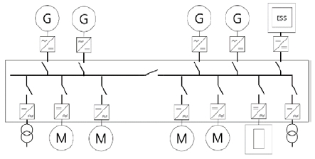
The DC distribution system was provided by Edison in the early 1880s. Because the DC power distribution system has a frequency of “0” a reactive component is absent, loss due to reactive power is non-existent, and the weight and volume of the power plant that does not contain the transformer and LC filter are reduced significantly. Another advantage is that compared to the same AC voltage ratio, the insulation can be reduced. However, it was not used for a long period of time because it is the most important power converter component of the system with limited capacity of semiconductor devices, and because it is costly. However, with the recent diffusion of power semiconductor devices with large capacities and high switching speeds has become smoother, power control and power conversion efficiency have increased, and the energy efficiency in cooperation with the ESS, which is caused by the spread of renewable energy, has increased the number of cases in which the ship also applies a DC distribution system. Figure 1 shows the configuration of the DC distribution system [4]-[7].
3. Propulsion motors for DC distribution of electric propulsion ship
3.1 Requirement for installation of propulsion motors for electric propulsion ship
Propulsion motors used in small-sized electric propulsion ships employing a DC distribution system are subject to many limitations for maintenance because they are installed in special environments, such as marine ships, which are poorly suited to moisture and oil in narrow spaces. Therefore, the marine propulsion motor must satisfy the following conditions [8][9]:
ㆍHigh power density
ㆍStructure resistance to mechanical vibration
ㆍEasy maintenance
ㆍHigh reliability
3.2 Type of propulsion motor of electric propulsion ship
DC motors have been applied to propulsion motors of special ships such as ice breakers since the 1950s, as a result of easy speed control, large torque, and a wide control range. However, because of the operationally required brushes and commutators, high-speed applications are not suitable and are rarely used owing to shortcomings that require periodic maintenance.
Induction motors are mechanically robust, structurally simple, and easy to fabricate. In terms of price, it is cheaper than other electric motors. However, it is not easy to control the electric motors to generate large torques. Nevertheless, since the 1980s, with the development of power converter devices, the introduction of vector control algorithms has eased the control of torque, thus enabling driving at variable speeds; therefore, they have been applied to various fields.
A synchronous motor is a motor that, unlike an induction motor, rotates at a synchronized speed without slip. They are used in a wide range of fields from large-capacity to small-capacity devices. The rotor electromagnet is fabricated using a DC excitation circuit that supplies DC power. Recently, a permanent magnet synchronous motor demonstrating high efficiency, high power factor, and high output density using a permanent magnet instead of a DC excitation circuit has been applied in many fields.
BLDC motors exhibit similar electrical characteristics to DC motors. However, it is an electric motor with improved reliability by applying a control circuit for rectification that replaces the rectifier of the mechanical contact structure. Because mechanical contact is non-existent, it is possible to create a high-speed rotation and measure the motor speed accurately from the hole sensor, such that the speed control of the motor is easy. In addition, because the structure and shape of the motor are designed in the process of a brushless operation, the motor size can be reduced with a degree of freedom, which is advantageous.
4. Comparative analysis of propulsion motors for DC distribution
In this study, the system with an induction motor and the other system with a BLDC motor that are both used widely in all industrial fields are compared to model suitable electric propulsion motors for the DC power distribution of small-sized electric propulsion ships.
4.1 System modeling using induction motor as propulsion motor
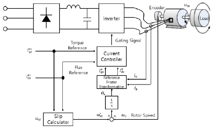
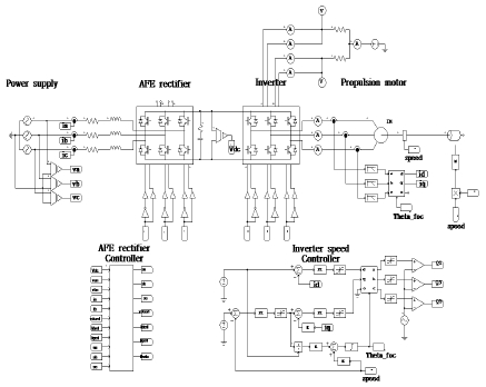
Indirect vector control was applied for the speed control of the induction motor. This technique is shown in Figure 2. The slip command angular velocity was calculated using the flux current, torque current, and motor constant on the synchronous rotational coordinate system. Further, the magnetic flux angle was estimated using the integrated value of the calculated slip angular velocity and the rotor speed. The stator current supplied to the motor was controlled by dividing the stator current into components that are orthogonal to the reference flux for a high-performance torque and flux control [10].
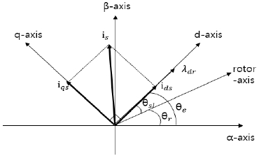
As observed, the stator current supplied to the motor is separated and controlled by the magnetic flux component current ids and the torque component current iqs for a high-performance torque and magnetic flux control. Figure 3 shows the flux and torque currents on the synchronous rotational coordinate system.
The indirect vector control based on the rotor flux was controlled such that the rotor flux exists only in the d axial component; therefore, Equation (1) holds.
| (1) |
As shown in Equation (2), the torque is proportional to iqs; therefore, iqs is called the torque component current. In the case of constant flux control, the rotor flux can be controlled by ids; therefore, ids is called the flux component current.
| (2) |
When ids is constant, the equation of slip can be expressed by the following Equation (3). Because the position of the rotor is the integral value of the motor speed and the slip command angular speed, the following Equation (4) is obtained.
| (3) |
| (4) |
4.2 System modeling using BLDC motor as propulsion motor
The BLDC motor flows current according to the position of the permanent magnet of the rotor such that the rotator rotates in a certain direction. It changes the winding of the stator that can generate the magnetic flux along with the current flow such that the force is generated continuously in the rotor [11][12]. At this time, a two-phase excitation method in which only two phases out of a three-phase winding are excited and the other phase is not excited.
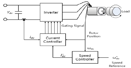
The speed / current controller of the BLDC motor using the two-phase excitation method can be represented by a block diagram, as shown in Figure 4. The speed is controlled by controlling the current, as shown in Equation (5). In this case, the output of the speed controller is the current command of the motor, and a current sensor is required to measure the actual current of the motor.
| (5) |
To control the BLDC motor with square-wave outputs in which the current, flux, and counter-electromotive force, the expressions of the abc coordinate system of Equation (6) to Equation (8) are used directly without performing the coordinate transformation applied to the vector control used in the induction motor.
| (6) |
| (7) |
| (8) |
As shown in Equation (9), the torque of the motor when driven in the two-phase excitation mode has the same magnitude as those of the excited currents of the two phases, except for the phase current switching period. However, because the flow direction is the opposite, it is expressed as an arithmetic product of the magnitude e of the counter electromotive force and the current magnitude i.
| (9) |
5. Comparative analysis of simulation results
In this study, the induction motor and BLDC motor were simulated based on the speed response, heat loss of the inverter, and harmonics in the output of power source using the PSIM program; the results were compared and analyzed.
5.1 System configuration for simulation of induction motor
Figure 5 shows the circuit for the simulation of the electric propulsion system using an induction motor. Table 2 shows the parameter constant of the induction motor.
5.2 System configuration for simulation of BLDC motor
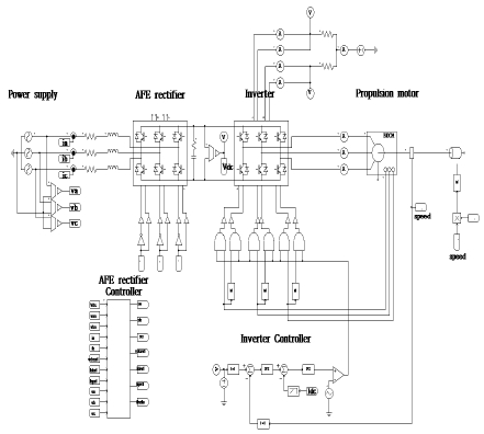
Figure 6 shows the circuit for the simulation of the electric propulsion system using the BLDC motor. Table 3 shows the parameters of the BLDC motor.
5.3 Simulation results
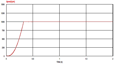
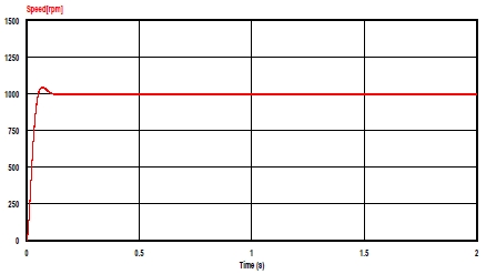
First, Figure 7 and Figure 8 show the speed response characteristics when the induction motor and BLDC motor are applied to the propulsion motor of a DC distribution electric propulsion ship, respectively. The induction motor uses the indirect vector control technique for speed control, and the speed current controller using the two-phase excitation method is applied to the BLDC motor. As observed, the speed of the propulsion motor according to the step speed command shows the speed control characteristic that follows the command value well.
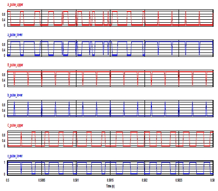
Figure 9 shows the gating signal to turn on/off the power semiconductor devices of inverters in the induction motor during 0.5 - 0.503 s. Because the sinusoidal wave pulse width modulation with 5 kHz switching frequency using the indirect vector control technique was applied, the on/off pulse signal applied to the inverter switching device is as follows. Switching state “1” denotes that the switch in an inverter leg is turned on, and “0” denotes that the switch in an inverter leg is turned off.
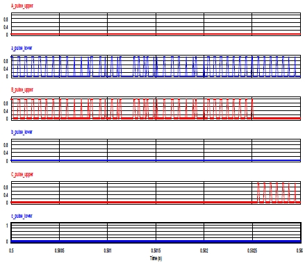
Figure 10 shows the gating signal to turn on/off the power semiconductor devices of the inverters in the BLDC motor during 0.5 - 0.503 s. Because the speed current controller using the two-phase excitation method was applied, the on/off pulse signal applied to the inverter switching device decreased as follows.
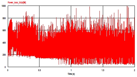
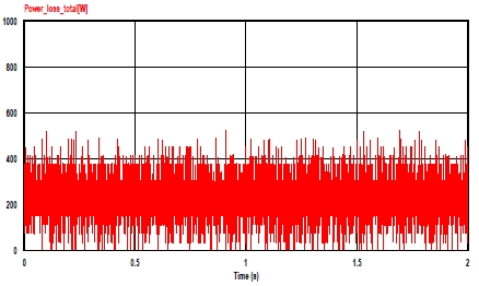
Figure 11 and Figure 12 show the switching losses generated by the inverter of the induction motor and BLDC motor when the switching frequency of the inverter is 5 kHz and the speed reference is 1000 rpm. When using an induction motor, the heat loss generated by the inverter is higher than when the BLDC motor is used owing to the inverter control method.
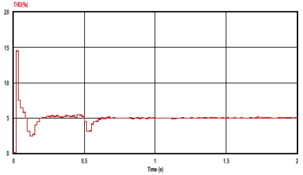
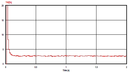
Figure 13 and Figure 14 show the result of the total harmonic distortion factor in the input side of the AC source under the same conditions. The total harmonic distortion of an electric propulsion system using an induction motor is approximately 5%, and a system using a BLDC motor demonstrates a total harmonic distortion of approximately 3%. Both types of rectifiers satisfy the requirements stipulated in IEEE Std519-2014, but the total harmonic distortion of the system using BLDC motors is lower. This indicates that harmonics can reduce the impact on the overall power system and other equipment.
6. Conclusion
In this study, induction and BLDC motors were simulated to select a suitable propulsion motor for a small-sized electric propulsion ship using a DC distribution system. Both of these motors exhibited excellent speed response characteristics. The simulation results indicated that the inverter control method of a BLDC motor using the two-phase excitation method reduced the heat loss in the power conversion of the inverter compared with an induction motor system using a vector control algorithm. In addition, it was confirmed that the total harmonic distortion ratio of the BLDC system on the power source side was reduced compared to the system using the induction motor owing to the difference in the switching frequency of the inverter.
From the comparison and simulation, it was discovered that operation over a wide speed range was possible when an electric propulsion motor was applied to a small electric propulsion boat for coastal navigation. Further, the BLDC motor with a low switching loss of the inverter and low harmonics was valid.
Acknowledgments
This work was supported by the Korea Institute of Energy Technology Evaluation and Planning (KETEP) and the Ministry of Trade, Industry & Energy (MOTIE) of the Republic of Korea (No. 20173010032240).
References
- International Maritime Organization, http://www.imo.org/en/MediaCentre/MeetingSummaries/MEPC/Pages/MEPC-72nd-session.aspx Accessed April 13, 2018.
- International Maritime Organization, http://www.imo.org/en/MediaCentre/HotTopics/Pages/Sulphur-2020.aspx Accessed April 18, 2018.
- S. J. Choi, A Study on the Development of Air Pollutants and Greenhouse Gases Emission Factor and Emission Estimation from the Domestic Coastal Shipping, Atmospheric Environment and Risk Assessment Research, Project no. 13-05-14, National Institute of Environmental Research, (2015), (in Korean).
- Y. K. Son, S. H. Choi, S. Y. Lee, S. Y. Kim, and S. K. Seol, “Application of DC distribution IPS to a 10t class fishing boat”, Journal of the Korean Institute of Power Electronics, 22(4), p353-359, (2017), (in Korean).
-
D. J. Hammerstrom, “AC versus DC distribution systems-Did we get it right”, 2007 IEEE Power engineering society general meeting, p1-5, (2007), (in USA).
[https://doi.org/10.1109/pes.2007.386130]

- M. Starke, and B. Ozpineci, “AC versus DC distribution : A loss comparison”, Proceedings of the IEEE/PES conference and exposition, (2008).
- D. K. Kim, J. S. Kim, and S. H. Kim, “An optimized design development of electric system on offshore unit”, Proceedings of the KOSOMES fall conference, p215-215, (2016), (in Korean).
- J. T. Park, K. W. Kim, K. C. Kim, and K. J. Lee, “A trend on the technical development of electric motors for ship propulsions”, Proceedings of the KIEE summer conference, p632-634, (2001), (in Korean).
- S. H. Kim, J. S. Kim, S. J. Oh, and H. S. Kim, Practical Electric Machinery, Seoul, Korea: Sanghagdang, (2011), (in Korean).
-
B. Wu, High-power Converters and AC Drives, New Jersey, Canada, Wiley Interscience, (2006).
[https://doi.org/10.1002/0471773719]

- S. H. Kim, Motor Control, Seoul, Korea, Bokdu, (2016), (in Korean).
-
A. Sathyan, Y. J. Lee, and A. Emadi, “An FPGA-based novel digital PWM control scheme for BLDC motor drives”, IEEE TRANSACTIONS ON INDUSTRIAL ELECTRONICS, 56(8), p3040-3049, (2009).
[https://doi.org/10.1109/tie.2009.2022067]


