Soft magnetic-core coupler suitable for low-frequency band power-line communication
Copyright © The Korean Society of Marine Engineering
This is an Open Access article distributed under the terms of the Creative Commons Attribution Non-Commercial License (http://creativecommons.org/licenses/by-nc/3.0), which permits unrestricted non-commercial use, distribution, and reproduction in any medium, provided the original work is properly cited.
Abstract
In this study, we implemented inductive couplers suitable for low-bandwidth powerline communication and conducted a transmission experiment on a power line of 900m length. The nanocrystalline and ferrite was used as soft magnetic core materials for implementing the toroidal core type and cut-core type couplers. Since the magnetic flux density distribution of the toroidal core is concentrated in the core and the influence of the leakage magnetic flux can be ignored, the insertion loss in the bandwidth range is small. However, in the cut core, the insertion loss in the low-frequency region largely occurs due to the leakage magnetic flux through the air gap. In order to compensate the large insertion loss in the low frequency region for the cut core, the inductance of the core was varied by adjusting the turns ratio of the coupler. We confirmed that when the broadband inductive coupler has a winding ratio of 3:10 or 5:10 and is applied to a narrow band power line communication system, it can communicate at a distance of at least 900 m with a data rate of 9.6 kbps.
Keywords:
Power-line communication, Soft magnetic material, Induction-type coupler, Ferrite core, Nanocrystalline core1. Introduction
Power-line communication is a form of communication that superimposes communication signals onto the alternating current power source (50-60 Hz) of power lines that were originally designed to transmit power. The communication signals are separated at the receiver through the high frequency filter. In the power-line communication system, terminals can be supplied more cheaply than in wireless communications, and the investment costs are cheap because existing power lines can be used without modification. Because there is no need to spend money on transmission lines, this reduces the high installation costs, which are a drawback of conventional wired or wireless high-speed communication networks [1].
Power-line communication technologies can be classified as broadband and narrowband communication. Narrowband power-line communication uses a carrier frequency below 500 kHz and usually provides data rate up to tens of kbps. This approach is already commercialized and being used for smart building, home automation, renewable energy generation and so on. Broadband power-line communication provides a data rate of several hundred Mbps, and can support a high-speed internet services [2][3].
Signal coupling methods include contact and non-contact type couplers. Contact type couplers use a special coupling capacitor to make electrical contact with the power line. The power line sheathing must be removed, and a direct connection must be made. Therefore, this method has the drawbacks of making it necessary to ensure electrical stability and to perform a complex installation process. Furthermore, it cannot be used on high voltage powerline. In comparison, the non-contact type couplers referred to the inductive coupler can be installed just by mounting on the powerline without damaging the power line. The non-contact method is easy to work and has excellent stability. It is therefore a more economical way. The inductive coupler is a core component that performs two roles: extracting communication signals from the power line through electromagnetic induction using soft magnetic material or providing the communication signal to the power line. It can be used regardless of the amount of voltage or current of the powerline and can be applied to both narrowband and broadband communication networks [4].
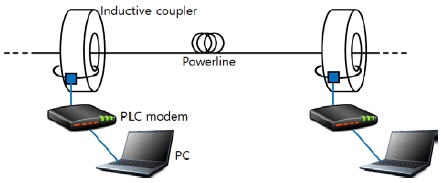
This study focuses on inductive power-line communication using a soft magnetic-core coupler that is suitable for long-distance low-bandwidth communication on an existing power line. Long-distance power-line communication can be utilized in a variety of applications. However, the power line was originally built to deliver 60 Hz of electrical energy. Therefore, as the frequency of the power line communication signal increases, the high frequency loss of the power line increases, so the communication speed and distance are limited. The power line sheathing (which was only for insulation requirements), the chosen branch circuits, and the various load devices that were installed also have an effect on power line signal transmission characteristics. Because of this, the high frequency communication signals superimposed on the power line are subject to considerable attenuation and the signal loss and distortion due to branching must be accommodated. Furthermore, a variety of interference signals from the outside that cannot be blocked by the insulation sheathing must be overcome. To overcome these drawbacks, studies have been performed on the characteristics of non-contact couplers that can perform communications in low-frequency bands rather than high-frequency bands. In particular, power lines such as underground lines, aerial lines, and optical ground wires are thick and long; this makes it very difficult to implement a power-line communication system through the contact coupler method. In such a case, non-contact power-line communication can be an effective approach.
2. Low-Speed Power-Line Modem and Soft Magnetic-Cores
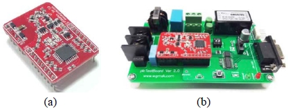
The low-bandwidth power line communication modem used in this study is an ultra-small module commercialized by EM Tech in Korea as shown in Figure 1 (a) [5]. This module is applicable to both power line communication system using AC or DC power line and supports communication speed of 9.6-57.6 kbps. The signal modulation method of the modem is spread frequency shift-keying modulation, and the carrier center frequency is 307.2 kHz [6]. The modem is installed on the test board shown in Figure 1 (b), and it performs power line communication test through RS-232 or RS-485 interface.
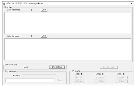
We used the packet monitoring program shown in Figure 2 provided by EM Tech to verify the power line communication performance. When the port is set through the port setting and TxTest (Run) is started, the package transmission and reception can be performed through the power line communication system. The packet transmission was calculated as the ratio of the received package to the transmitted packet.
Figure 3 shows the six soft magnetic cores used to develop the inductive coupler, and each core is distinguished by size, material, and shape. Each sample was given a name from A to F.
Table 1 shows the specification of each soft magnetic core. Structurally, it is distinguished as a toroidal core and a cut core. The cut core is a special shape that allows an inductive coupler to be used in a power line through the non-contact method. In terms of magnetic core material, it is divided into ferrite and nanocrystalline. The initial permeability and saturation magnetic density of the nanocrystalline are approximately three times higher than those of the ferrite core.
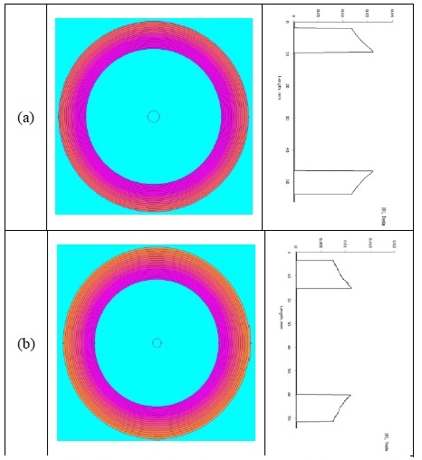
Figure 4 shows the result of calculating the magnetic flux density distribution of the toroidal core at a current of 0.1A [7]. Since the core permeability is much larger than neighboring domains, flux density is concentrated inside the core, and it decreases away from the core center to the edges. The average magnetic flux density of the nanocrystalline core shown in Figure 4 (a) is about 0.03T. On the other hand, the ferrite core is approximately 0.01T as shown in Figure 4 (b), which is three times smaller than that of the nanocrystalline core.
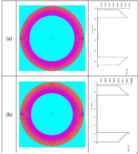
Figure 5 shows the magnetic flux density distribution of a cut core with a total air gap of 200 μm. The average magnetic flux density at a primary current of 0.1 A is 0.6 × 10⁻³ T, which is very low value compared to the toroidal core. For cut cores such as sample E and F, flux leakage through the air gap occurs, so the internal residual flux density is smaller than the toroidal cores. Therefore, the toroidal type coupler has higher coupling efficiency than the cut type coupler. The problem is that the toroidal coupler is almost impossible to install without cutting the existing power line. There is no choice but to use the cut type coupler. In order to maintain the communication performance by using cut type coupler in the powerline communication system, a method of compensating flux leakage should be considered, which will be discussed in Section 3.
3. Experiment Results and Discussions
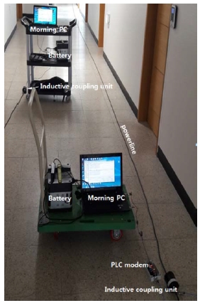
Figure 6 shows an experimental setup of a low-bandwidth powerline communication system using a cut-type coupler. A BNC connector was used to connect the coupler to the low-bandwidth modem. A serial communication cable using RS-232 was used between the modem and PC. The EM Tech program was running on the monitoring PC to measure the degree of transmission packet loss depending on the communication distance.
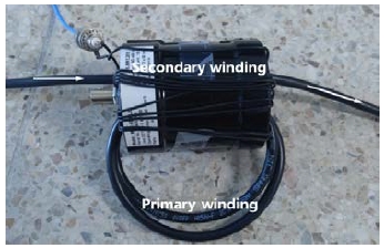
Figure 7 shows the structure of the cut-core type coupler. The power cable was used as the primary wire, and the other wire that connected to the power line modem was used as the secondary one.
3.1 Inductive coupler with turns ratio of 1:1
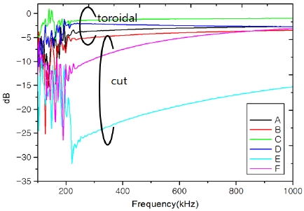
The insertion loss (S21) of the coupler with turns ratio of 1:1 is shown in Figure 8. At a communication frequency of 307.2 kHz, the insertion loss of the toroidal core is less than -5 dB, but the insertion loss of the cut core is more than -10 dB. Signal coupling efficiency is expected to be lower when cut-core couplers are used for power line communications, which will result in a decrease in bandwidth.
Table 2 shows the packet reception ratio measured on a test bed with a power line length of 200 m. The toroidal core type coupler had a 100% packet reception rate up to a distance of 200m. However, the cur core type coupler had a packet reception rate of 0% even at a distance of 50 m. These results confirmed that the cut cores having a large insertion loss as shown in Fig. 8 had a smaller signal coupling efficiency than the toroidal cores. It is clear that the insertion loss due to the air gap greatly affects the performance of low-bandwidth power line communication.
The inductance of the soft magnetic core is given by Equation (1).
| (1) |
Here, N is the winding density, lgap is the air gap length, μ0 is the permeability of air, and A is the cross-section area of the cut core. Equation (1) shows that as the air gap length increases, the inductance decreases proportionally. But, the winding ratio can be adjusted to compensate for the loss of inductance. This approach can improve the packet reception ratio of the narrowband powerline communication system with a cut-core type coupler.
3.2 Inductive coupler with turns ratio of M:N
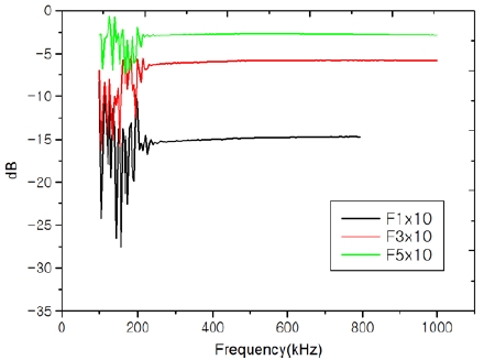
From Equation (1), if there is an air gap in the core, the core inductance decreases and the signal coupling efficiency is worse than the toroidal core. In this study, we tried to increase the number of turns of coupler in order to improve the signal coupling efficiency of the cut-core type coupler to compensate the reduction of the inductance due to the air gap. The number of turns of the secondary winding of the cut core type coupler was fixed at 10 times, the number of turns of the primary winding was changed 1, 3, and 5 times, and the insertion loss due to the air gap was measured and shown in Figure 9. It has a loss of -15 dB at a 1:10 turns ratio but -5 dB loss at a 3:10 turns ratio and -2 dB loss at turns ratio of 5:10. Even if the number of secondary windings is fixed, the insertion loss of the low frequency band can be reduced by increasing the primary winding number.
Based on the results of measuring the insertion loss for each winding ratio, the packet reception ratio was measured using the m: n winding ratio coupler as shown in Figure 10. The transmitter and receiver inductive couplers were connected to the powerline modem via a BNC connector and the powerline modem performed serial communication with the monitoring PC via RS-232.
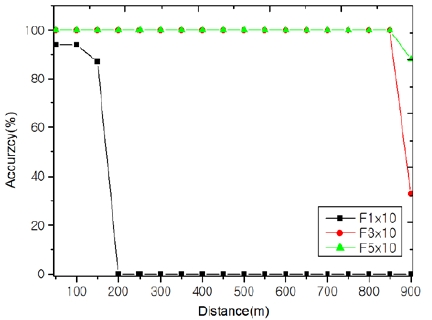
Figure 11 shows the result of the packet reception ratio for each communication distance. Couplers with a 1: 10 turn ratio received 94 out of 100 outgoing packets at communication distances up to 100 meters, but at a distance of 150 meters, the packet reception rate dropped to 87 percent. However, communication was not made on power lines of 150 m or more. The coupler with turns ratio of 3:10 showed a 100% packet reception rate at a distance of 850m and dropped to 33% at 850m or more. A coupler with a 5: 10 turns ratio showed 100% packet reception at a distance of 850 meters, but only 88% of packets successfully received at 850 meters. Because the total length of the power line used in the experiment is 900 m, it is believed that the accuracy of packet reception is reduced at 850 m or more due to the influence of the reflected wave noise at the line end point.
4. Conclusions
In this paper, an inductive coupler suitable for long-distance narrow-bandwidth power line communication system was developed. Since the frequency response of the coupler depends on the turns ratio, we tried to find the adequate turns ratio that can minimize the insertion loss of the low frequency region. The 100% packet reception rate was confirmed at 850 m at a data rate of 9.6 kbps in a coupler of 5:10 turns ratio. Based on the results of this study, it is expected that the transmission distance can be extended to several km by minimizing the insertion loss of the inductive coupler for narrowband power line communication.
Acknowledgments
This study was conducted with the support of the 2018 regional specialized industry promotion project (P0002774) financed by the Ministry of SMEs and Startups and the senior researcher support project of the National Research Foundation of Korea (NRF2017 R1A2B4010993) financed by the Ministry of Science and Technology.
References
-
H. K. Jun, H. S Kim, K. S. Jung, and K. R. Sohn, “Development of bypass unit for ship area network based on legacy-line communication”, Journal of the Korean Society of Marine Engineering, 39(3), p292-297, (2015), (in Korean).
[https://doi.org/10.5916/jkosme.2015.39.3.292]

- K. R Sohn, J. H Jung, and S. H Yang, “Performance of magnetic induction communications using inductive coupler unit for power-line communication”, Proceedings of KICS Conference, 2017(1), p785, (2017), (in Korean).
- K. R Sohn, J. H Jung, and S. H Yang, “Energy harvesting properties using electromagnetic induction of soft magnetic core”, proceedings of KICS Conference, 2017(11), p680, (2017), (in Korean).
-
S. H Yang, J. H Jung, and K. R Sohn, “Inductive powerline communication performance comparison using nano-crystalline alloy and ferrite coupling device in ship”, Journal of the Korean Institute of Communications and Information Sciences, 43(4), p740-746, (2018), (in Korean).
[https://doi.org/10.7840/kics.2018.43.4.740]

- EM Tech, Power Line Communication Modem, http://www.wgmsk.com/sub3/sub2.html Accessed August 30, 2018.
-
T. Schaub, “Spread frequency shift keying”, IEEE Transactions on Communications, 42(2/ 3/ 4), p1056-1064, (1994).
[https://doi.org/10.1109/tcomm.1994.580214]

- Finite Element Method Magnetics, http://www.femm.info/wiki/HomePage Accessed August 30, 2018.

