Study on swirl flow in a draft tube of a bulb hydro turbine model
Copyright © The Korean Society of Marine Engineering
This is an Open Access article distributed under the terms of the Creative Commons Attribution Non-Commercial License (http://creativecommons.org/licenses/by-nc/3.0), which permits unrestricted non-commercial use, distribution, and reproduction in any medium, provided the original work is properly cited.
Abstract
The present study focuses on the effect of swirl flow in a draft tube on the performance of a bulb hydro turbine model at various turbine operating conditions by CFD analysis. First, the performance characteristics of the bulb turbine model were investigated. Subsequently, four operating conditions were chosen for loss analysis in the downstream region of the turbine model. Next, the swirl number was calculated along the downstream region at different turbine operating conditions. Moreover, the internal flow was examined to understand the turbine performance characteristics. From this study, it was observed that the swirl number was proportional to the loss in the downstream region of the turbine model. For the high swirl number, i.e., PL1 and PL2 conditions, the internal flow investigation indicated a relatively large recirculation region in the downstream region. For the low swirl number, i.e., BEP condition, a smooth streamline was found. Thus, the high efficiency of the turbine model is illustrated in this condition.
Keywords:
Bulb hydro turbine model, Performance characteristics, Swirl flow, Draft tube, Computational fluid dynamic (CFD) analysis1. Introduction
The presence of swirl flows often results in unstable flows in the draft tube of hydraulic reaction turbines. At the design point, water turbines generally operate with little swirl entering the draft tube and no flow separations exist. However, at off-design, the flow leaving the turbine exhibits a large swirling component [1]. Owing to the negative influence of swirl flows to turbine performance, many researchers have investigated swirl flow characteristics in the downstream of a turbine runner. S. W. Armfield et al. [2] developed a single sweep algorithm to predict both swirling and non-swirling flows in conical diffusers. Y. Senoo et al. [3] experimentally examined five conical diffusers with different divergence angles to clarify the relationship between the swirl and the pressure recovery coefficient. From a range of swirl angles at the inlet, R. P. Lohmann et al. [4] investigated the performance of diffusers of various lengths, area ratios, and cant angles experimentally. M. Nishi et al. [5] summarized the relation between the formation of a vortex rope and a swirl flow in a model draft tube. E. T. V. Dauricio et al. [6] used a commercial software to analyze the effect of swirl flows in four different diffusers and identified the relationship between swirl velocity profile and diffuser wall slope. Understanding swirl flows in a draft tube of a bulb turbine can provide the designer with useful information on the behavior of recirculation flow that can reduce the efficiency of the turbine, and provide methods to control swirl flows. However, studies on swirl flow behaviors and methods to suppress swirl flows in a draft tube of a bulb turbine are scarce compared to those pertaining to radial turbines. Many methods can be used to suppress swirl flows in a draft tube of a Francis turbine [7]-[10]. Given the energy injected in the draft tube cone, these methods can be divided into active, passive, or semipassive control [10]. Z. D. Qian et al. [8] conducted numerical simulations to mitigate the instabilities in a draft tube of a Francis turbine using air admission-an active method. The study indicated that the amplitude and pressure difference in the cross section of the draft tube decreases while the blade frequency pressure pulsation increases in front of the runner. Passive control methods include fins mounted on the runner cone [9], or using J-grooves [11]-[13]. An experimental investigation of swirl flow in a conical diffuser was conducted by J. Kurokawa et al. [12] that utilized the J-groove. The J-groove illustrated that it could significantly mitigate the swirl intensity and pressure pulsation in the diffuser. In other applications of the J-groove, it improved the stable performance curve of a mixed pump, as reported by S. L. Saha et al. [14]. From his study, a shallow J-groove shape and its location can suppress the performance curve instability and increase the efficiency in the flow range of the performance curve of a mixed pump. The present study is a preliminary study to understand swirl flows in the draft tube of a bulb turbine model at design and off-design operating conditions. Owing to positive the effects of the J-groove in suppressing swirl flows in a draft tube of a turbine, a draft tube with J-groove installation will be applied to suppress swirl flows in the draft tube of the bulb turbine model in the next study.
2. Turbine model and numerical method
2.1 Turbine model
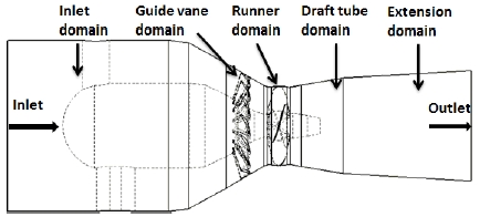
The bulb hydro turbine model consists of five fluid domains, as shown in Figure 1. The flow enters through the inlet domain first and subsequently passes through the adjustable guide vane to the runner and exits to the downstream area via the draft tube and extension domains. The class 115-kW bulb turbine model operates under the following design conditions: effective pressure head of water across the turbine H = 12.5 m; flow rate passing through the turbine Q = 1.074 m3/s; rotational speed n = 1800 min-1. The turbine model contains four runner blades and 16 guide vanes. The runner diameter is D = 0.3646 m.
2.2 Numerical method
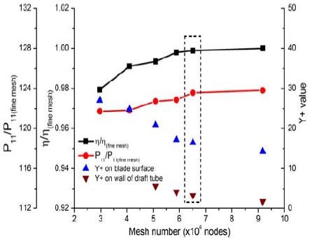
The swirl flow characteristics in the draft tube of a hydro turbine have been studied by many researchers in the past decades. Computational fluid dynamics (CFD) analysis is an efficient method for investigating swirl flow characteristics in a hydro turbine. The present study used the commercial CFD code of ANSYS CFX version 18.1 [15] to solve the Reynolds-averaged Navier–Stokes equations. The mesh of the whole fluid domain was generated using ANSYS ICEM [15]. A grid validation test was performed according to the different number of nodes as indicated in Figure 2 that represents the relationship between the different mesh grids, and that of the normalized efficiency (η/η(fine mesh)) and unit power (P11/P11(fine mesh)) by those of a fine mesh. The shear stress transport (SST) model accounts for the transport of turbulent shear stress and yields highly accurate predictions of the onset and amount of flow separation under adverse pressure gradients [16]-[18]. Therefore, the SST turbulence model was used for all steady-state numerical calculations presented herein.
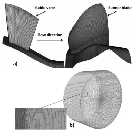
Table 1 indicates the boundary conditions for the flow field. The mesh for one pitch of the guide vane, runner blade, and full draft tube domain are indicated in Figure 3. Because the relative efficiency and unit power of the turbine model do not change in the ranges over 6.5 million nodes, a grid of 6.5 million nodes was used for the numerical calculation in the present study. To achieve reasonable swirl flow characteristics in the draft tube, the mesh near the wall of the draft tube was refined in the radial direction in the selected mesh. The near wall treatment y+ value of the draft tube domain is 3.3 in the chosen grid.
3. Results and discussion
3.1 Performance curves
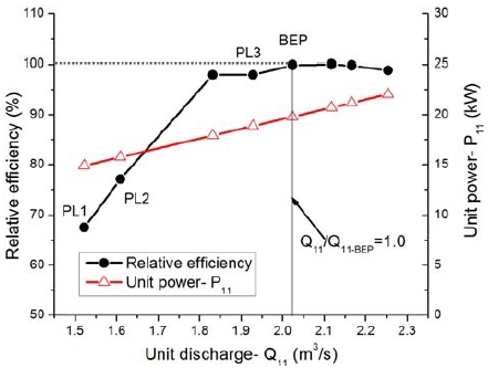
The performance curve of the bulb turbine model was calculated at various discharge conditions of the turbine under a constant runner rotational speed of 1800 min-1. The relative efficiency of the turbine model at each discharge condition was normalized by the efficiency at the best efficiency point (BEP). The unit discharge (Q11) and unit power (P11) (shown in Equation (1) and Equation (2)) were employed for the performance characteristics of the bulb turbine model.
| (1) |
| (2) |
Figure 4 represents the performance characteristics of the bulb turbine model by the CFD analysis results. According to the relative efficiency of the turbine, four operating conditions were selected: partial load condition 1 (PL1-Q/QBEP=66%), partial load condition 2 (PL2-Q/QBEP=72%), partial load condition 3 (PL3-Q/QBEP=92%), and best efficiency point (BEP) (Q/QBEP=100%). The figure illustrates that the turbine efficiency decreases significantly in the off-design conditions (PL1 and PL2) and slightly reduces at PL3.
3.2 Loss analysis
The losses of the draft tube and extension domains were calculated using Equation (3), where Δp is the pressure difference on the analyzed domain.
| (3) |
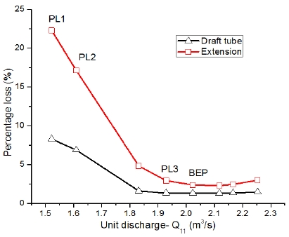
The losses in the draft tube and extension domains at various turbine discharge conditions are represented in Figure 5. The figure indicates that the draft tube and extension domains exhibit a relatively high loss in the PL1 and PL2 conditions. The lowest losses in the two domains were found in the BEP condition. Owing to the different hydraulic losses in every operating condition, the internal flow in the downstream of the turbine model at each operating condition will be investigated and compared.
3.3 Swirl number distribution
A swirl flow is generated into a draft tube by a rotating runner in a hydro turbine. Depending on the swirl intensity, the flow in a draft tube can generate a vortex rope and subsequently causes an unstable flow in the downstream of a hydro turbine [5][19]. To determine the effect of swirl flow in the draft tube on the turbine performance, the swirl number was calculated at various locations along the draft tube and extension domains. The swirl number (Sno.) [5] is defined as Equation (4) below:
| (4) |
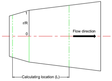
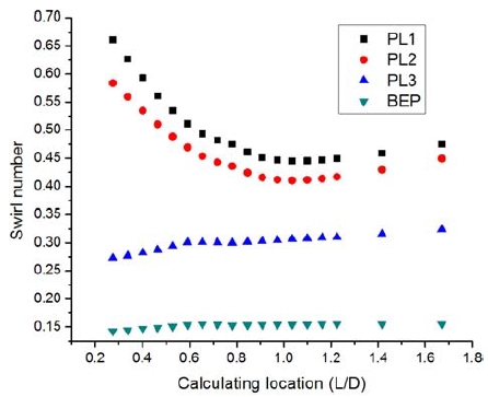
where Vu, Vm, r, and R are the circumferential, axial velocities, radial position, and draft tube cross-sectional radius, respectively. The calculating location for the swirl flow is shown in Figure 6. The swirl number distribution along the downstream turbine model is represented in Figure 7. The x-axis is the location normalized by the runner diameter, D. The swirl numbers in the PL1, PL2, and PL3 conditions are higher than that of the BEP condition. The swirl number increases when the turbine discharge decreases. This corresponds to a rapid and significant loss in the downstream turbine model at the partial load conditions. In the PL3 and BEP conditions, the swirl numbers at the locations far from the runner are slightly higher than those at the locations near the runner.
3.4 Streamline and components velocity coefficient distribution
The streamline distributions on the center plane for the four examined conditions are illustrated in Figure 8. The figure clearly shows the different streamline distributions at each turbine operating conditions. In the PL1 and PL2 conditions, a relatively large recirculation flow was found in the draft tube and extension domains. It causes the high loss and swirl number in the domains. The recirculation flow is also located in the downstream turbine as well as in the PL3 condition. In the BEP condition, the flow field exhibits a smooth streamline distribution. Therefore, the loss and swirl number are small values in the BEP condition. In addition, the components’ velocity distributions were investigated to understand the streamline distribution in the draft tube. The calculating locations of the components’ velocities are presented in Figure 6. Figure 9 and Figure 10 represent the axial velocity coefficient, , and circumferential velocity coefficient, distributions, respectively, at four turbine operating conditions.
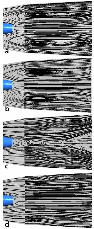
Streamline distribution on the center plane in the (a) PL1, (b) PL2, (c) PL3, and (d) BEP operating conditions
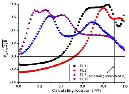
Axial velocity coefficient distribution from center to diffuser wall at various turbine operating conditions
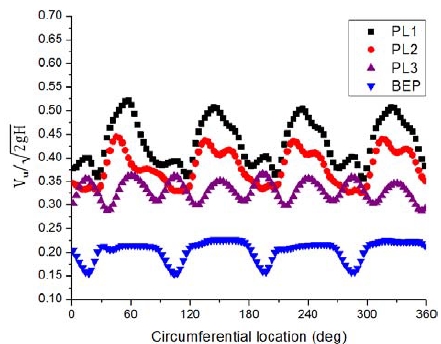
Circumferential velocity coefficient distribution from center to diffuser wall at various turbine operating conditions
From Figure 9, the axial velocity coefficient in the PL1 and PL2 conditions are higher near the wall than when it is close to the center, where the flow direction is reversed. This generates a recirculation region in the high swirl number. The high swirl number induces the circumferential velocity coefficient found in the PL1 and PL2 conditions. In contrast, the small value of circumferential velocity coefficient is indicated in the BEP condition, which has relatively small swirl number. For the PL3 condition, the swirl number is lower than those in the PL1 and PL2 conditions. Therefore, it is not strong enough to cause a recirculation flow in the intermediary region. However, the recirculation area is found in the center region in the PL3 condition owing to the high circumferential and axial velocity coefficients near the center and widened fluid domain, as the draft tube shape and no runner hub, while the continuity equation is still applied. For the BEP condition, the swirl number and circumferential velocity coefficient are relatively small in comparison with other conditions. Thus, the BEP condition exhibits good flow distribution and achieves high performance.
4. Conclusions
The swirl flow characteristics in a draft tube at different operating conditions of a bulb hydro turbine model were investigated. From the CFD analysis result, it was observed that, the swirl intensity affected the turbine performance. An increase in swirl number in the draft tube caused increased loss in the region downstream the turbine model and thus reduced the turbine efficiency. The internal flow characteristics indicated that the small swirl number in the BEP condition resulted in a small circumferential velocity that was not strong enough to create a reverse flow in the downstream region. Therefore, a smooth streamline was found in the downstream region and high turbine efficiency was indicated in this condition. However, the relatively high swirl number in the PL1 and PL2 conditions (off-design conditions) caused the appearance of a large recirculation flow in the downstream region of the turbine model. The phenomenon should be suppressed to control the stability in the operating conditions of the turbine model. Hence, the application of the J-groove to suppress the phenomenon is required in future studies.
Acknowledgments
This work was supported by the New and Renewable Energy of the Korea Institute of Energy Technology Evaluation and Planning (KETEP) grant funded by the Korea Government Ministry of Trade, Industry and Energy (No. 20163010060340).
References
- P. Dörfler, M. Sick, and A. Coutu, Flow-Induced Pulsation and Vibration in Hydroeletric Machinery, Zurich, Switzerland, Springer Verlag London, (2012).
-
S. W. Armfield, and C. A. J. Fletcher, “Numerical simulation of swirling flow in diffusers”, International Journal For Numerical Methods in Fluid, 6(8), p541-556, (1986).
[https://doi.org/10.1002/fld.1650060805]

-
Y. Senoo, N. Kawaguchi, and T. Nagata, “Swirl flow in conical diffusers”, Bulletin of the JSME, 21(151), p112-119, (1978).
[https://doi.org/10.1299/jsme1958.21.112]

-
R. P. Lohmann, S. J. Markowski, and E. T. Brookman, “Swirling flow through annular diffusers with conical walls”, Journal of Fluids Engineering, 101(2), p224-229, (1979).
[https://doi.org/10.1115/1.3448939]

-
M. Nishi, and S. Liu, “An outlook on the draft-tube-surge study”, International Journal of Fluid Machinery and Systems, 6(1), p33-48, (2013).
[https://doi.org/10.5293/ijfms.2013.6.1.033]

- E. T. V. Daurico, and C. R. Andrade, “Numerical analysis of swirl effects on conical diffuser flows”, Journal of Aerospace Technology and Management, 9(1), p91-100, (2017).
- C. Zhenmu, P. M. Singh, and Y. D. Choi, “Suppession of unsteady swirl flow in the draft tube of a Francis hydro turbine model using J-Groove”, Journal of Mechanical Science and Technology, 31(12), p5813-5820, (2017).
- Z. D. Quian, J. D. Yang, and W. X. Huai, “Numerical simulation and analysis of pressure pulsation in Francis hydraulic turbine with air admission”, Journal of Hydrodynamic, 19(4), p467-472, (2007).
-
M. Nishi, X. M. Wang, K. Yoshida, T. Takahashi, and T. Tsukamoto, “An experimental study on fins, their role in control of the draft tube surging”, Hydraulic Machinery and Cavitation, p905-914, (1996).
[https://doi.org/10.1007/978-94-010-9385-9_92]

-
A. L. Bosioc, R. Susan-Resiga, S. Muntean, and C. Tanasa, “Unsteady pressure analysis of a swirling flow with vortex rope and axial water injection in a discharge cone”, Journal of Fluids Engineeing, 134(8), p0811041-08110411, (2012).
[https://doi.org/10.1115/1.4007074]

-
Y D. Choi, J. Kurokawa, and H. Imamura, “Suppression of cavitation in inducers by J-Groove”, Journal of Fluid Engineering, 129(1), p15-22, (2007).
[https://doi.org/10.1115/1.2375126]

-
J. Kurokawa, H. Imamura, and Y. D. Choi, “Effect of J-Groove on the suppression of swirl flow in a conical diffuser”, Journal of Fluids Engineering, 132(7), p071101-071108, (2010).
[https://doi.org/10.1115/1.4001899]

-
J. Kurokawa, “J-Groove technique for suppressing various anomalous flow phenomenon in turbomachines”, Internaltional Journal of Fluid Machinery and Systems, 4(1), p1-13, (2011).
[https://doi.org/10.5293/ijfms.2011.4.1.001]

-
S. L. Saha, J. Kurokawa, J. Matsui, and H. Imamura, “Suppression of performance curve instability of a mixed flow pump by use of J-Groove”, Journal of Fluids Engineering, 122(3), p592-597, (2000).
[https://doi.org/10.1115/1.1287855]

- ANSYS Ins, “ANSYS CFX Documentation”, ver. 18.1, http://www.ansys.com Accessed May 16, 2017.
-
D. Jost, A. Lipej, and P. Meznar, “Numerical prediction of efficiency, cavitation and unsteady phenomena in water turbines”, Proceedings of the 9th Biennial ASME conference on engineering systems design and analysis, p157-166, (2008).
[https://doi.org/10.1115/esda2008-59563]

-
F. R. Menter, “Two-equation Eddy-Viscosity turbulence models for engineering applications”, AIAA Journal, 32(8), p1598-1605, (1994).
[https://doi.org/10.2514/3.12149]

-
T. H. Shih, W. W. Liou, A. Shabbir, Z. Yang, and J. Zhu, “A new k-εEddy viscosity model for high Reynolds number turbulent flows”, Computers and Fluids, 24(3), p227-238, (1995).
[https://doi.org/10.1016/0045-7930(94)00032-t]

-
S. Muntean, T. Ciocan, R. F. Susan-Resiga, M. Cervantes, and H. Nilsson, “Mathematical, numerical and experimental analysis of the swirling flow at a Kaplan runner outlet”, IOP Conference Series: Earth and Environmental Science, 15(3), p032001, (2012).
[https://doi.org/10.1088/1755-1315/15/3/032001]


