Control method for forming roller in dome spinning process of 34CrMo4 alloy steel pipe at elevated temperature
Copyright © The Korean Society of Marine Engineering
This is an Open Access article distributed under the terms of the Creative Commons Attribution Non-Commercial License (http://creativecommons.org/licenses/by-nc/3.0), which permits unrestricted non-commercial use, distribution, and reproduction in any medium, provided the original work is properly cited.
Abstract
In this study, we developed a control method for a forming roller used in a spinning process at an elevated temperature for manufacturing dome parts of a high-pressure vessel. The sequence and forming path of the forming roller were determined by the number of passes in the hot spinning process and dome radius. To verify the reliability of the proposed method, an FE (finite element) analysis under the Forge software environment and spinning experiments were performed using a 34CrMo4 alloy steel pipe with an outer diameter of 559 mm and thickness of 16.5 mm. The FE analysis and experimental results indicated that the roller control method provided a successful dome shape.
Keywords:
Dome spinning, High-pressure vessel, Forming path, FE analysis, Plastic zone distribution1. Introduction
Dome spinning process is a universally applicable metal forming process to manufacture axisymmetric parts, such as steel CNG (compressed natural gas) tanks and supporting cone of engines, in aerospace, weapon, and automotive industries.
Previous literature on the metal spinning process was based on its theoretical and experimental investigation. In this study, the spinning of tubes is reviewed with the objective of understanding the basic mechanisms underlying the spinning process, important variables, tools used, and techniques implemented by S. Kalpakjian and S. Rajagopal [1]. The thickness distribution of a spin-formed dome in an Al pressure vessel was determined experimentally based on a simple formulation proposed by N. Akkus and M. Kawahara [2]. M. Joseph Davidson et al. studied the optimization of process parameters in a flow-forming process for the maximum deformation using the Taguchi method [3].
Over the last decade, many researchers have applied an FE (finite element) analysis to the metal spinning process. Hua et al. developed a 3D elastic-plastic model for the three-roller backward spinning of a cylindrical workpiece [4]. A coupled set of experiments and FE analysis were conducted by M. S. Mohebbi and A. Akbarzadeh to investigate the evolution of redundant strains in a single roller flow-forming process [5]. New techniques were developed by S. Y. Jiang et al. The ball spinning process was used to manufacture nickel-titanium shape memory alloy tubes at an elevated temperature using a rigid viscoplastic FE method [6]. H. Zoghi et al. presented an enhanced FE analysis of a material deformation and strain distribution in the spinning of 42CrMo steel tubes at an elevated temperature [7]. X. Zhang et al. proposed an optimized neck-spinning technique for the seamless cylinder of pure titanium by reversing the material flowing direction with respect to the feeding direction of the spinning roller [8].
All these studies have focused on the influence of process variables and tool movements on the closed ends of tube, and its plastic deformation behavior. It is difficult to apply these techniques during actual production due to a lack of research on the forming path of forming rollers.
In this study, the authors aim to develop a control method for a forming roller used in the dome spinning process of 34CrMo4 alloy steel pipes at an elevated temperature. The control method was established using a 3D FE spinning model under the Forge software environment. The effects of the developed method on the dome shape and strain distribution were analyzed. These analytical results were verified through hot spinning tests using a 34CrMo4 alloy steel pipe.
2. FE analysis of pipe spinning process
2.1 FE analysis model
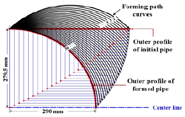
The spinning tool path curves designed by a geometrical construction method are shown in Figure 1. These tool path curves have over 30 passes with an increment of 9.3 and 9.7 mm in the pipe's radial and axial directions, respectively.
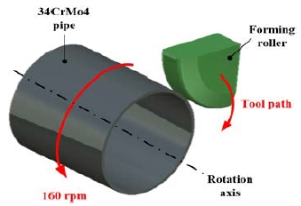
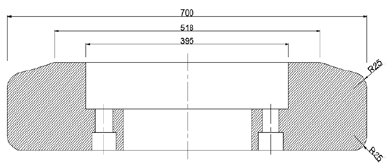
A 3D thermo-mechanical FE model, shown in Figure 2, is developed using the Forge software to prove the effectiveness of the proposed control method. A coupled thermo-mechanical tetrahedron element with four nodes is adopted for the model calculation to avoid a convergence problem and reduce computation time. Figure 3 shows the required dimensions of the forming roller.
Relevant parameters needed for the FE model are shown in Table 1. The forming roller is set as a rigid body. The roller diameter and height are 700 and 150 mm, respectively. H. Lexian and B. M. Dariani reported the effect of the roller nose radius and release angle on the forming quality in a hot spinning process [9]. The stability and forming quality improves by increasing the roller nose radius and reducing the release angle. Hence, the corner radius and release angle of the forming roller used in this study are 25 mm and 0 º, respectively. The roller feeding speed is 50 mm·s-1 and the pipe rotates at a constant rotation speed of 160 rpm to ensure a good balance between process stability and operation speed. Thirty successive forming passes are required to form the final dome shaped product. The forming roller is applied the deformation zone by synchronous longitudinal and radial forming path.
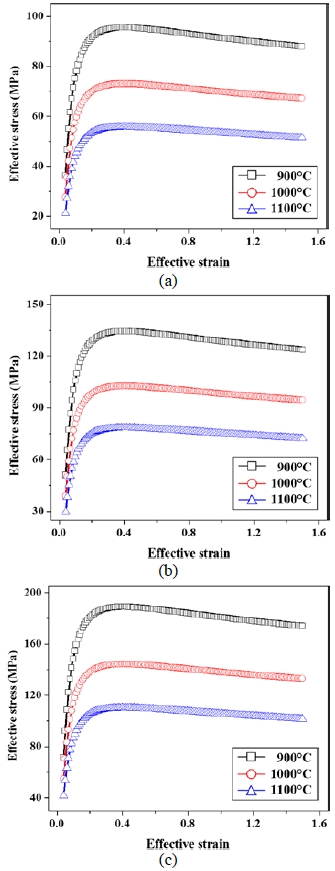
The dimensions of an initial pipe, Do and to, were taken to be 559 mm and 16.5 mm, respectively. Since the FE model for hot spinning process always involves high number of elements and boundary conditions, and therefore requires very long computation times. So length of an initial workpiece, L0 is shortly restricted to 400 mm. The used material was 34CrMo4 alloy steel, which is equivalent to the American grade alloy AISI4135. Its density, elastic modulus and Poisson’s ratio were 7850 kg·m-3, 200GPa and 0.29, respectively. Initial temperature of steel pipe heated by furnace is 1050 °C. The stress-strain curves of a 34CrMo4 alloy steel obtained under different temperatures and strain rates are given in Figure 4. Coulomb friction model is adopted to friction of contact surfaces between forming roller and steel pipe, and the friction coefficient is 0.2. The used temperature-dependent physical properties of steel alloys are derived from Metal Supplier Online of America: specific heat of 778 J·kg-1·ºC-1, conductivity of 35.5 W·m-1·C-1, emissivity of 0.88, respectively.
2.2 Results of FE analysis
Pipe plastic deformation means that plastic zone penetrates the pipe section, and pipe produces the plastic deformation by reducing radius and increasing the thickness in the spinning process. The expanding rule of plastic zone can be revealed in process of pipe plastic penetration. In order to investigate the deformation behavior in pipe spinning process, the expanding rule of plastic zone should be carried out firstly [10][11].
Figure 5 shows the plastic zone distributions of different passes during the pipe spinning process. Blue areas indicate the elastic zone, and areas with other colors mean the plastic zone with different effective strain. Since the material was actually restricted by forming path, effective strain was obviously increased at end of the pipe. There is no wrinkling of folding defect and maximum effective strain at the end of pipe is about 8.0 during the hot spinning process.
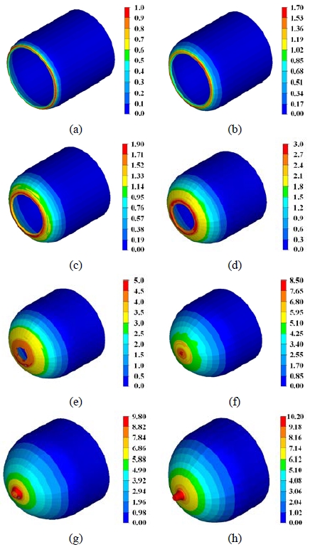
Plastic zone distribution of deformed pipe during hot spinning process: (a) 5 pass; (b) 10 pass; (c) 15 pass; (d) 20 pass; (e) 25 pass; (f) 30 pass; (g) 35 pass; (h) 40 pass
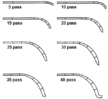
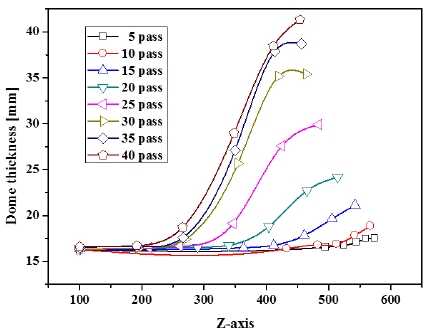
The comparison of cross section and thickness distribution at each pass is shown in Figure 6 and Figure 7, respectively. Material at the end of pipe was smoothly deformed in a semi-spherical type. The maximum thickness at the end of the dome shape is 41.33 mm. The maximum difference between the thickness of the initial pipe and that obtained from the FE-analysis is about 24.83 mm. A large thickness is necessary for manufacturing seamless steel CNG tanks because deep screw cuts are required for the boss connection. The proposed control method ensures the circular dome shape with a large boss thickness.
3. Experimental verification
3.1 Experimental procedures
A hot spinning experiment was conducted on a pipe-spinning machine from NK Co., Ltd in Korea, to experimentally verify the effectiveness of the proposed control method and obtain the sufficient thickness for a screw cut at the boss of the dome. The specifications of this spinning machine included a maximum external diameter of 914.4 mm and forming force of approximately 75 tons.
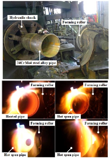
General experimental conditions are the same as those listed in Table 1. A 34CrMo4 steel alloy pipe of 16.5 mm thickness (outer diameter: 559 mm, inner diameter: 526 mm) was first heated to about 1050 °C in a furnace and this temperature was maintained using gas flame torches on the deformation zone of the pipe during the entire process. The heated pipe was clamped by a large hydraulic chuck while the forming roller performed the deformation using the designed forming path. The roller feeding speed was 500 mm·s-1 and the chuck turning speed was 160 rpm during the spinning process. A deformed specimen was cut using a wire-EDM machine and the cross section was measured.
3.2 Results of pipe spinning experiment
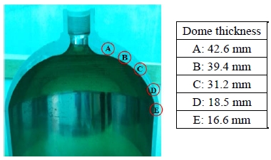
Figure 8 represents the pipe spinning experiment carried out using an industrial hot spinning machine. The deformed pipe configuration during the hot spinning process is shown in Figure 8 and Figure 9. The maximum dome thickness is 42.6 mm. The experimental results indicated that the proposed method led to a successful dome shape with the highest dimensional precision and a large boss thickness. Hence, this method is suitable for use in an actual hot dome spinning process.
4. Conclusion
The control method for a forming roller was investigated using a 3D FE analysis. The effectiveness of the proposed method was validated by hot spinning experiments of the dome parts. The main conclusions are as follows:
- (1) The proposed control method was posited based on a geometrical construction drawing.
- (2) The expanding rules of the plastic zone were clearly revealed in the hot spinning process. As the spinning pass increases, the plastic zone expands towards the end of the deformed dome shapes.
- (3) The control method for a forming roller could successfully operate according to the requirements of a hot spinning mill and provide a successful dome shape with a large boss thickness.
- (4) These results provide valuable guidelines for the process design in an actual dome spinning production.
Acknowledgments
This work was supported by the National Research Foundation of Korea(NRF) grant funded by the Korea government(MSIP; Ministry of Science, ICT & Future Planning) (No.2017R1C1B5017016).
References
-
S. Kalpakjian, and S. Rajagopal, “Spinning of tubes: A review”, Journal of Applied Metal Working, 2(3), p211-223, (1982).
[https://doi.org/10.1007/bf02834039]

-
N. Akkus, and M. Kawahara, “An experimental and analytical study on dome forming of seamless Al tube by spinning process”, Journal of Materials Processing Technology, 173(2), p145-150, (2006).
[https://doi.org/10.1016/j.jmatprotec.2005.11.011]

- M. Joseph Davidson, K. Balasubramanian, and G. R. N. Tagore, “Experimental investigation on flow-forming of AA6061 alloy-A Taguchi approach”, Journal of Materials Processing Technology, 200(1-3), p283-287, (2008).
-
F. A. Hua, Y. S. Yang, Y. N. Zhang, M. H. Guo, D. Y. Guo, W. H. Tong, and Z. Q. Hu, “Three-dimensional finite element analysis of tube spinning”, Journal of Materials Processing Technology, 168(1), p68-74, (2005).
[https://doi.org/10.1016/j.jmatprotec.2004.10.014]

-
M. S. Mohebbi, and A. Akbarzadeh, “Experimental study and FEM analysis of redundant strains in flow forming of tubes”, Journal of Materials Processing Technology, 210(2), p389-395, (2010).
[https://doi.org/10.1016/j.jmatprotec.2009.09.028]

-
S. Y. Jiang, Y. Q. Zhang, Y. N. Zhao, M. Tang, and C. F. Li, “Finite element simulation of ball spinning of NiTi shape memory alloy tube based on variable temperature field”, Transactions of Nonferrous Metals Society of China, 23(3), p781-787, (2013).
[https://doi.org/10.1016/s1003-6326(13)62529-7]

-
H. Zoghi, A. F. Arezoodar, and M. Sayeaftabi, “Enhanced finite element analysis of material deformation and strain distribution in spinning of 42CrMo steel tubes at elevated temperature”, Materials and Design, 47, p234-242, (2013).
[https://doi.org/10.1016/j.matdes.2012.11.049]

-
X. Zhang, L. Zhao, T. Wen, Z. Yin, D. Han, Z. Bai, and J. Jiang, “An optimized neck-spinning method for improving the inner surface quality of titanium domes”, Procedia Engineering, 207, p1731-1736, (2017).
[https://doi.org/10.1016/j.proeng.2017.10.930]

-
H. Lexian, and B. M. Dariani, “Effect of roller nose radius and release angle on the forming quality of a hot-spinning process using a non-linear finite element shell analysis”, Proceedings of the Institution of Mechanical Engineers, Part B Journal of Engineering Manufacture, 223(6), p713-722, (2009).
[https://doi.org/10.1243/09544054jem1445]

-
L. Hua, D. S. Qian, and L. B. Pan, “Deformation behaviors and conditions in L-section profile cold ring rolling”, Journal of Materials Processing Technology, 209(11), p5087-5096, (2009).
[https://doi.org/10.1016/j.jmatprotec.2009.02.007]

-
D. H. Lee, B. M. Kim, and K. H. Lee, “Design of pure-radial ring rolling process by using advanced feasible forming condition”, Journal of the Korean Society of Marine Engineering, 42(4), p287-292, (2018), (in Korean).
[https://doi.org/10.5916/jkosme.2018.42.4.287]


