Fabrication and characterization of novel stretchable force sensors using melt electrospinning
Copyright © The Korean Society of Marine Engineering
This is an Open Access article distributed under the terms of the Creative Commons Attribution Non-Commercial License (http://creativecommons.org/licenses/by-nc/3.0), which permits unrestricted non-commercial use, distribution, and reproduction in any medium, provided the original work is properly cited.
Abstract
We have designed stretchable force sensors using a melt electrospinning technique, and fabricated novel, stretchable force sensors using poly(ε-caprolactone) (PCL). Four types of PCL sensors have been fabricated and tested: laser-machined PCL microfiber sheet, laser-machined PCL sheet, non-machined PCL microfiber sheet, and non-machined PCL sheet. After electrospinning, molding, and laser processing, the sheets are metal sputter-coated with gold particles to increase their electrical conductivity. Because of the auxetic effect attributable to the geometric structure of the materials, the strength and thickness of the sensor can be automatically adjusted in response to applied forces. The materials have the ability to return to their neutral state after stress dissipation. This stretchable sensor is attachable on various substrates and is manageable by applied external load or strain. To confirm that our sensors work in a practical setting, we have successfully attached and tested the sensors on a real human hand.
Keywords:
Melt electrospinning, Auxetic structure, Microfibers, Force & Strain sensors, Laser machining1. Introduction
Rehabilitative devices are able to improve hand functionality in people who have experienced hand injuries or accidents. A special division of robotics, rehabilitation robotics, targets construction of robotic instruments as a method to support people who are impaired by accident or who require assistance due to age or weakness [1]-[3]. This area of research deals with user-friendly designs, actuator systems that supply power to prostheses, control mechanisms that mimic the human tendon operation system, and sensor systems for substrate position detection [1]-[3].
The sensor system to detect position consists of identifying the environment through various types of sensors, such as sonar sensors, force sensors, and so on. Sensors for rehabilitation have to be a portable size, light weight, have good position-sensing accuracy, and be attachable to human skin [1]. Force sensors are one of the main candidates to adequately meet these goals [4][5]. However, attaching a force sensor to human skin is not a simple task, since the force sensor cannot stretch the way skin does. The elastic sensors studied in this study can be attached to human skin and can show changes in force and strain.
Recent research has studied micro-electromechanical systems (MEMS) as force sensors [5][6] but the application has proved challenging due to the difficulty of attaching the fabricated sensor to skin. Thus, melt electrospinning is suggested as a technology to manufacture attachable, stretchable sensors. The process of melt electrospinning has received significant attention because of its potential to manufacture polymer fibers ranging in size from nanometer to micrometer [4][7]. Melt electrospinning is considered ongoing research in the field of polymer processing to produce polymer fibers with advantageous properties including mechanical, controllable physical, and topographical [8]-[10]. As a relatively inexpensive production method, melt electrospinning offers a high fabrication capability for the production of force sensors.
Poly(ε-caprolactone) (PCL), a biodegradable, saturated polyester, has been used in this study as our polymer of choice. The PCL microfibers fabricated by melt electrospinning have easily tailorable mechanical properties. PCL is a hydrophobic, biocompatible polymer with a very low melting point (65 °C) and is one of the most commonly used synthetic polymers in biomedical engineering applications.
In this study, we demonstrated that PCL and machined microfiber sheets act as force sensors, which translates force into mechanical extension, thereby measuring the resistance. Key characteristics of the stretched sensors are very important to be considered when designing such sensors. These characteristics include having low hysteresis, large strain, high elasticity, ease of fabrication, and direct measurements, while they should be also easy to mount and have an outstanding degree of reproducibility [1]-[3][4]. In addition, because of the auxetic nature of this material’s geometric structure, the sensor is automatically adjustable with strength and thickness in response to applied forces, and it has the memory ability to return to its neutral state on dissipation of the stresses.
Our stretchable sensor is able to be attached on the preferred substrate (skin) and could potentially be controlled by applying an extensional force or strain. We have created four sets of samples: no-machined PCL sheet (NPS), no-machined PCL microfiber sheet (NMS), machined PCL sheet (MMS), and machined PCL microfiber sheet (MPS). All samples were transferred to a gold coating device in order to deposit gold nanoparticles to fabricate electrically conductive sheets. The samples are experimentally characterized to measure their conductivity. All samples are pressed under a mass of 5 kg for 10 min in order to affix the conductive particles. Finally, we demonstrate that the sensors work properly on human skin.
2. Fabrication methods of sensor sheets
2.1 Melt electrospinning
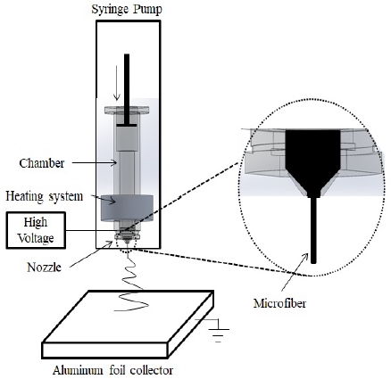
Poly(ε-caprolactone) (PCL) (Mn ~ 45,000) was supplied by Sigma Aldrich, USA. Its melting point is 60 °C. Customized melt electrospinning devices (Figure 1) include a computer numerical control (CNC) machine (K2 CNC Inc., USA), a customized chamber press, a syringe pump (New Era Pump Systems Inc., USA), custom-made melting chambers, and interchangeable, on-demand nozzles. The flat pointed nozzles used to extrude the melt were produced from aluminum 6061 with an internal diameter of 200 μm (± 10 μm) [4].
A high voltage, 20 kV, was applied using a voltage supply (Gamma High Pressure Research Inc., USA) through the molten electrospinning process which allowed a working distance of 5 cm between the nozzle and the aluminum foil collector. PCL granules were dispensed into the melting chamber via nozzles and then heated to the preferred temperature of 80 °C. The zero shear rate viscosity of the PCL was measured as 291.5 Pa∙s using an ARES-G2 rheometer (TA Instruments, USA) at a parallel plate geometry with 25-mm spacing. An aluminum foilcovered wood plate was used as a counter electrode for the collection of mesh loop microfibers [4].
2.2 Press molding
We made a PCL sheet by creating a custom mold of aluminum 6061. The thickness of the PCL is set to about 0.3 mm, which is the gap left between the top plate and the bottom plate. The bottom plate was preheated to 80 °C to melt the PCL polymer. The top plate was pressed together with the bottom plate to form a sheet made of PCL polymer. The fabricated PCL sheet was separated from the mold after cooling [4].
2.3. Laser processing
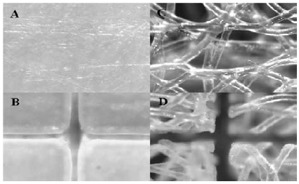
A femtosecond laser processing system was used to create auxetic patterns on PCL microfiber and PCL sheets. The amplified Ti: Sapphire femtosecond laser processing system emitted 120 fs pulses at a center wavelength of 800 nm. The repetition rate was 1 kHz, and the output power of 0.35 W was measured by a power meter. The laser beam reflected by mirrors was focused by a 20X objective with a 0.42 numerical aperture (Mitutoyo Co., Japan). A computer-controlled electronic shutter was used to properly turn the laser beam on and off at desired locations on the PCL and PCL microfiber sheets. Figure 2 shows the non-machined samples (A, C) and machined samples (B, D) of the PCL sheets and microfiber sheets [4].
2.4. Gold particle coating
The PCL and PCL microfiber samples were coated with gold particles using a metal sputter coater (Anatech Hummer VI). The Hummer VI parameters were set to 75 mTorr Argon, 10 mA current, and a 2 min run time. The samples were coated with gold particles 15 nm thick to ensure sufficient electrical conductivity.
2.5. Tensile and Resistance test
An ALIO vertical micro-milling machine was used to continuously stretch the four kinds of samples. A Kistler dynamometer (MiniDyn 9256C1) and the milling machine simultaneously measured tensile force and elongation distance. Resistance data was acquired in real time by an Agilent multimeter (Agilent 34411A). Custom-made clamps hold the samples in the center of the dynamometer. Force and resistance data are recorded simultaneously.
2.6 Manufacturing of sensor sheets
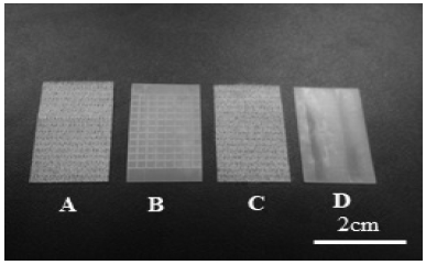
In the fabrication process, samples of PCL and microfiber sheets, shown in Figure 3, of 32.64 mm (length) x 17.92 mm (width) x 0.3 mm (thickness) were affixed on glass slides by double-sided sticky tape on a CNC 3-axis stage. The speed of machining was fixed at 0.3 mm/s to prevent the samples from collapsing and repeated 3 times with a 0.1-mm depth increase each to confirm that the samples were machined completely. The overall mechanical properties of the stretchable force sensor depend on the relative magnitudes of the stretching and openness of the system.
3. Experimental results
3.1. Tensile test
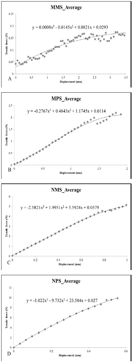
Samples from the four different sensors, machined microfiber sheet (MMS), machined PCL sheet (MPS), non-machined microfiber sheet (NMS), and non-machined PCL sheet (NPS), were characterized mechanically. Force-strain curves are shown in Figure 4. Figure 4 (a) and C illustrate the mechanical behavior of the microfiber sheets. By increasing the strain to 3.5 mm and 1.0 mm, respectively, the MMS and NMS samples showed a linear force strain behavior which demonstrates its linear elastic property. The machined sample showed an approximately 3.5-times greater displacement distance than the no–machined sample. Similarly, Figure 4 (b) and Figure 4 (d) show the behavior of the PCL sheets. The displacement distance of the MPS, 2.0 mm, is approximately 3.2 times larger than the 0.6 mm displacement of the NPS. The machined samples (MMS, MPS) required more force than the non-machined samples (NMS, NPS) required to achieve the same displacement.
3.2. Resistance test
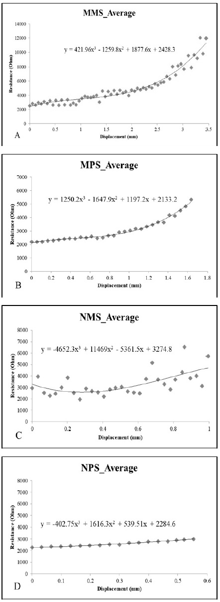
Figure 5 shows the resistance versus strain for the four force sensors. Figure 5 (a) and Figure 5 (c) show changes in resistance when tensile force is applied to the microfiber sheets. The resistance showed a significant increase from an initial value of about 2 kΩ to a maximum of 12 kΩ and 7 kΩ for MMS and NMS, respectively, when the displacements increased to 3.5 mm and 1.0 mm, respectively. Figure 5 (b) and Figure 5 (d) show the effect of strain on resistance of the PCL sheets. As expected from their structures, linear behavior was partially observed. The MPS and NPS samples’ resistance increased to about 5 kΩ and 1 kΩ, respectively, from an initial value of 2 kΩ, by increasing the strain distance to 1.65 mm and 0.58 mm, respectively.
3.3. Force vs. Resistance test
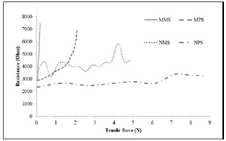
Figure 6 shows the results for the applied force and measured resistance for the four force sensor sets. All samples were electrically isolated but could be mechanically connected. For example, the MPS sample was mechanically separated at a displacement of 1.8 mm, but the sample was electrically isolated at 1.65 mm. We assumed that all samples were both electrically and mechanically separated when the data showed an electrical break that matched the tensile distance in both the mechanical and electrical results. In other words, due to the nature of the auxetic design and PCL microfiber geometry, the samples were easily stretched due to a small tensile force.
The MMS samples showed a significant increase in resistance as force is applied compared to MPS samples. MMS averaged 14.4 kΩ∙N-1. The MPS presented linear behavior between 0 and 1.7 N, but as force continued to increase, it presented an exponential curve. MPS averaged 0.4 kΩ-∙N-1.
The NMS and NPS samples required much more force than MMS and MPS samples to stretch because they had non-auxetic structures. NMS showed widely varying resistance at continuous tension due to the movement of the gold particles among microfibers, though we tried to affix the gold particles to the samples. The average sensitivity of NMS was approximately 0.2 kΩ∙N-1. NPS was the most difficult among the four samples to stretch, as shown in Figure 4 (d). Since the sample is stretched only 0.5 mm, the dispersion of the resistance was less than 1 kΩ. The average sensitivity of NPS is 0.17 kΩ∙N-1..
3.4. Practical test on the skin of a human wrist
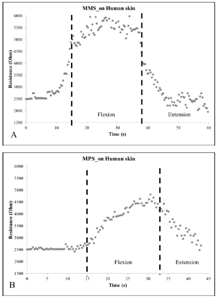
MPS and MMS sensors were used to conduct this resistance test on human skin since NPS and NMS sensors do not have auxetic structures. MPS and MMS sensors were attached to the skin of the wrist. The wrist was bent from the neutral position (0 °) to the maximum bending position (70 °), causing the sensor to deform about 1.5 mm, and then returned to the neutral position. Figure 7 (a) and Figure 7 (b) show the results for the wrist skin resistance test for the MMS and MPS sensors. MMS increased from 2.5 kΩ to 5.8 kΩ while MPS increased from 2.5 kΩ to 4.6 kΩ. In other words, the MMS was more sensitive than the MPS regarding deformation. Resistance through the MMS also increased and decreased more rapidly and smoothly than that through MPS.
4. Conclusions
We have investigated the characteristics of force stretchable sensors made of PCL materials with auxetic mechanisms, fabricated using melt electrospinning technology and micromachining. We have been able to process and characterize the mechanical and electrical properties of these four novel types of sensors, MMS, MPS, NMS, and NPS. We can also effectively study the effects of force and deformation on the measurement of resistance. The average sensitivity of these sensors was reported as 14.4 kΩ∙N-1, 0.4 kΩ∙N-1, 0.2 kΩ∙N-1, and 0.17 kΩ∙N-1 for MMS, MPS, NMS, and NPS sensors, respectively. The MMS sensor was suitable for applications requiring the highest sensitivity. In addition, the data confirmed that MMS sensors were more sensitive and smoother than MPS when deformed on human skin.
Acknowledgments
This work was supported by the Korea Maritime And Ocean University Research Fund, 2018.
References
- V. Bundhoo, E. Haslam, B. Birch, and E. J. Park, “A shape memory alloy-based tendon-driven actuation system for biomimetic artificial fingers: I. design and evaluation”, Robotica, 27(1), p131-146, (2009).
- G. Gilardi, E. Haslam, V. Bundhoo, and E. J. Park, “A shape memory alloy-based tendon-driven actuation system for biomimetic artificial fingers: II. Modelling and control”, Robotica, 28(5), p675-687, (2010).
-
J. Ko, M. B. G. Jun, G. Gilardi, E. Haslam, and E. J. Park, “Fuzzy PWM-PID control of cocontracing antagonistic shape memory alloy muscle pairs in an artificial finger”, Mechatronics, 21(7), p1190-1202, (2011).
[https://doi.org/10.1016/j.mechatronics.2011.07.003]

-
J. Ko, S. Bhullar, Y. Cho, and M. B. G. Jun, “Design and fabrication of auxetic stretchable force sensor for hand rehabilitation”, Smart Materials and Structure, 24(7), (2015).
[https://doi.org/10.1088/0964-1726/24/7/075027]

-
A. Koochi, A. Farrokhabadi, and M. Abadyan, “Modeling the size dependent instability of NEMS sensor/actuator made of nano-wire with circular cross-section”, Microsystem Technologies, 21(2), p355-364, (2015).
[https://doi.org/10.1007/s00542-014-2183-y]

-
N. K. S. Lee, R. S. Goonetilleke, Y. S. Cheung, and G. M. Y. So, “A Flexible encapsulated MEMS pressure sensor system for biomechanical applications”, Microsystem Technologies, 7(2), p55-62, (2001).
[https://doi.org/10.1007/s005420100092]

-
J. Ko, N. K. Mohtaram, P. C. D. Lee, S. M. Willerth, and M. B. G. Jun, “Mathematical model for predicting topographical properties of poly (ε-caprolactone) melt electrospun scaffolds in various temperature and linear transitional speed”, Journal of Micromechanics and Microengineering, 25(4), 2015.03.23, (2015).
[https://doi.org/10.1088/0960-1317/25/4/045018]

-
J. Ko, S. Bhullar, N. K. Mohtaram, S. M. Willerth, and M. B. G. Jun, “Using mathematical modeling to control tpographical properties of poly (ε-caprolactone) melt electrospun scaffolds”, Journal of Micromechanics and Microengineering, 25(1), 2014.05.06, (2014).
[https://doi.org/10.1080/09205063.2013.830913]

-
J. Ko, D. Kan, and M. B. G. Jun, “Combining melt electrospinning and particulate leaching for fabrication of porous microfibers”, Manufacturing Letters, 3, p5-8, (2015).
[https://doi.org/10.1016/j.mfglet.2014.11.001]

-
J. Ko, N. K. Mohtaram, F. Ahmed, A. Montgomery, M. Carlson, P. C. D. Lee, S. M. Willerth, and M. B. G. Jun, “Fabrication of poly (ε-caprolactone) microfibers scaffolds with varying topography and mechanical properties for stem cell-based tissue engineering application”, Journal of Biomaterials Science Polymer Edition, 25(1), p1-17, (2014).
[https://doi.org/10.1080/09205063.2013.830913]


