Natural convection characteristics in a vertical open channel with partially heated surfaces
Copyright © The Korean Society of Marine Engineering
This is an Open Access article distributed under the terms of the Creative Commons Attribution Non-Commercial License (http://creativecommons.org/licenses/by-nc/3.0), which permits unrestricted non-commercial use, distribution, and reproduction in any medium, provided the original work is properly cited.
Abstract
This study presents open channel natural convection with separated boundary conditions. To quantify the natural convection characteristics, the aspect ratio (pitch versus height) and wall boundary aspect ratio (first-type boundary versus second-type boundary) were investigated between two vertical parallel plates. The convective heat transfer characteristics were evaluated numerically while the channel inlet is assigned to a fully developed velocity profile at a constant temperature. The steady-state, two-dimensional laminar natural convection was analyzed. The computational procedure was selected by the control volume method with pressure treatment using the body force weighted method. It is shown that the numerical and experimental results are in good agreement. The results showed that when the channel ratio decreased, the heated area deceased because mass flow rate increased. The Nusselt values linearly increased at increasing isothermal wall lengths.
Keywords:
Finite volume scheme, Heat sink, Natural convection heat transfer, Open channel flow1. Introduction
Natural convection in open channels occurs in many passive heat sink problems. A passive heat transfer method is not very efficient compared to an active heat transfer method. However, it is reliable and sustainable, and does not require extra power. Therefore, heat performance increases in heat generated systems are necessary to characterize the detailed heat transfer characteristics. Recently, high performance electronics components have been produced which are inevitably associated with high levels of heat. Thus, highly efficient thermal management of electronics in passive heat transfer methods is important to ensure a proper thermal management scheme in a system.
Z. Amine et al. [1] showed a detailed comparison of natural convection in a vertical open-ended channel. They suggested that for increased Rayleigh numbers, the flow elicited three-dimensional and turbulent characteristics. Thus, two-dimensional numerical simulations were not applicable for such ranges of increased Rayleigh numbers. P. Oosthuizen and J. T. Paul [2] presented natural convection heat transfer results for a narrow vertical flat plate and for uniform heat flux conditions. They considered a heated plate that was embedded in a larger plate with plane adiabatic surfaces. The recession areas decreased the mean Nusselt number. The authors concluded that the protrusion of the heat plate from the surface tended to increase the Nusselt numbers. Furthermore, K. Kitamura et al. [3] investigated natural convective flows around an array of vertical heated plates. They showed the influences of plate numbers on the heat transfer characteristics of the plates. P. H. Oosthuizen and J. T. Paul [4] published the natural convective heat transfer from a narrow vertical plate with a uniform surface heat flux and with different plate edge conditions. They derived the empirical equations for the mean heat transfer rate from the narrow plates. The protrusion of the heated surface improved the Nusselt numbers. This effect increased with decreasing heat flux Rayleigh numbers. M. Ghobadi and Y. Muzychka [5] researched the heat transfer and pressure drops in minichannel heat sinks. They concluded that the heat transfer increased in comparison to a straight channel with a similar length owing to the disturbance of the boundary. This disturbance also resulted in a pressure drop increase. M. Ahmadi et al. [6] investigated natural convection in vertical parallel plates. They used an integral method for steady-state external heat transfer from isothermal rectangular fins. They developed compact semi-analytical relations for quantifying the velocity and temperature distributions.
In this study, we investigated and analyzed two-dimensional, laminar natural convection heat transfer. The convective heat transfer characteristics in a heat sink with an open channel were also evaluated numerically with surfaces which were heated separately. Furthermore, the effects of the geometrical parameters on the open channel will be discussed in detail.
2. Mathematical Modeling
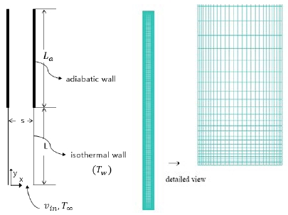
The schematic geometry which is a part of a plate-fin heat exchanger in vertical parallel plates is shown in Figure 1. The pitch of the plain vertical plates was compacted to obtain more plates in a confined geometry. This selected geometry was chosen for computational efficiency. The heat sources were located along the direction of longitudinal flow. Correspondingly, the heated boundary of a numerical domain was isothermal with separated adiabatic surfaces [7].
The detailed computational domain and grid view of the present study are shown in Figure 2. The pitch between the two vertical plates is s, the plate-fin height is Li, and the adiabatic wall length is La. Boundary conditions are described as shown in Figure 2.
In a steady-state condition, the two-dimensional governing equations of continuity, momentum, and energy, are used. The physical properties are assumed to be constant except for the density. The density property varies with temperature changes which cause natural convection heat transfer along the y-direction, according to the coordinate system shown in Figure 2. The governing equations can be expressed in accordance to the following equations [2]:
Continuity:
| (1) |
Momentum:
| (2) |
| (3) |
Energy:
| (4) |
At the entrance along the flow direction, the velocity profiles are not uniform for steady-state flow. Additionally, the mass conservation in an open channel considered that the in-flow and out-flow rates were the same even if the velocity profiles differed. However, the temperature profile was the same as that of the ambient temperature. At the inlet, the velocity profile could be derived based on the conservation of mass for control volumes that covered the entire domain between the two walls. If the channel length was adequately large, the velocity profile would reach a fully developed condition. At this cross-sectional area, mass conservation could be expressed in accordance to Equation (5):
| (5) |
Accordingly, the density at the outlet can be expressed in a linear form, in a manner similar to the Boussinesq approximation,
| (6) |
The velocity profile at a fully developed regime [3] is
| (7) |
Substituting Equation (7) into Equation (5) and rearrangement of the resulting equation leads to
| (8) |
At the outlet section, the flow has a fully developed velocity profile at the channel inlet when the flow channel is long enough to achieve a fully developed region.
To calculate the heat transfer performance, the average Nusselt number of a plate with a characteristic length, s, is evaluated based on the following equation:
where is the average heat transfer coefficient, s is the plate pitch, and k is the thermal conductivity.
A finite control volume method is used to calculate the numerical solution of coupled governing equations [8]. The density is approximated by the Boussinesq model to consider the heat transfer characteristics. To discretize the governing equations, the body force weighted scheme was used for the pressure, while the second-order upwind scheme was adopted for other primary variables. For the coupling of velocity and pressure, the pressure-implicit with splitting of operators (PISO) algorithm was used. This algorithm required fewer iterations and a less intensive computing effort. For the computation, the commercial software ANSYS Fluent [9] was used. For extra calculations, user defined functions in the C language were used.
3. Results and Discussion
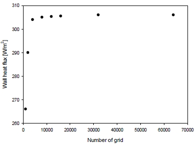
In this section, numerical results at various heat transfer values and geometry parameters are presented. Figure 3 shows the average heat flux at different grid numbers to ensure the accuracy of the numerical results and to identify a proper grid size. For the test case, the vertical plate temperature (Tw) was 360 K and the ambient temperature (T∞) was 320 K. The Prandtl number was 0.7 and the Rayleigh number was 1200. In order to examine the independence of the temperature field, the wall heat flux was estimated and plotted. Figure 3 shows that up to 15,000 grid numbers, the wall heat flux values change rapidly. However, beyond this grid number, the heat flux variation is less than 3 %. In this study, 30,000 grid numbers (or more) were used to ensure computational stability.
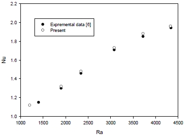
Figure 4 shows a comparison between the experimental and numerical results for the average Nusselt numbers at different Rayleigh numbers. These show good agreement. For the Rayleigh range from 1200 to 4330, the numerical results elicit slightly larger values. However, both the numerical and experimental results are acceptable.
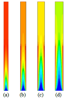
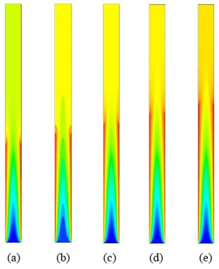
Figure 5 shows temperature color maps at different values of channel ratios (L/s) at Ra = 1200. The overheated vertical channel length ratio (La/Li) of the adiabatic wall is equal to unity. The total channel length over the plate pitch (L/s) changes from 13 to 20. Specifically, for Figure 5 (a), L/s = 20, for Figure 5 (b), L/s = 16, for Figure 5 (c), L/s = 13, and for Figure 5 (d), L/s = 11, respectively. As shown in Figure 5 (a), the heated section is large along the flow direction. This is because the mass flow rate is relatively small compared to other cases. When the channel ratio decreases, the heated area decreases because the mass flow rate increases. This means that an increased mass will transport heat easier.
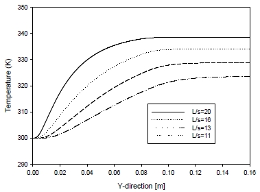
Figure 6 shows the temperature variations along the vertical axial direction. The temperature variation changes rapidly at first. Subsequently, the variation approaches an asymptotic maximum temperature value. When L/s = 20, the maximum temperature is elicited at the end of the heated walls. At subsequent times, the temperature is maintained constant. When L/s is 20, the maximum temperature is 338.5 K at the location of 95 mm along the y direction. Beyond this specific location, the temperature is maintained constant. Similarly, when L/s equals 16, the maximum temperature is 334.0 K at 105 mm. When L/s is 13, the maximum temperature is 328.8 K at 131 mm. In that case, the maximum temperature decreases dramatically. When L/s is 11, the maximum temperature is 323.6 K at 160 mm.
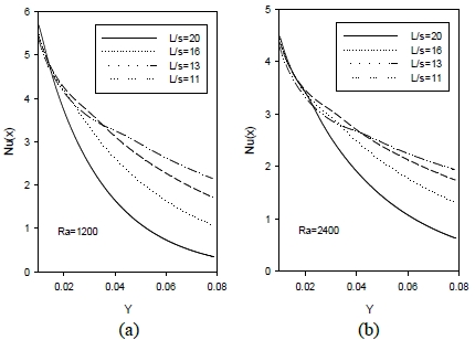
Figure 7 shows the local Nusselt number along the flow direction for different aspect ratios at Ra = 1200 (Figure 7 (a)) and Ra = 2400 (Figure 7 (b)), respectively. For Ra = 1200, the local Nusselt numbers decrease rapidly compared to the results elicited for Ra = 2400. However, for Ra = 2400, the change is more moderate compared to the previous case. This is attributed to the buoyancy effect along the flow direction. When the aspect ratio decreases, the local Nusselt ratio also decreases. This is because the decreased aspect ratio increases the total mass flux in the open channel.
Figure 8 shows various temperature maps at different heated aspect ratios. The ratios between of the isothermal wall length (Li) and adiabatic wall length (La) are (a) 1:1.4, (b) 1:1.2, (c) 1:1, (d) 1.2:1, and (e) 1.4:1. As shown in Figure 8, the entrance region yields almost identical temperature profiles. However, when the heated length increases, the temperature of the upper section in the open channel also increases.
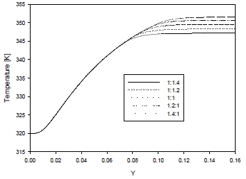
Figure 9 shows the center temperature variations along the y-direction at different aspects ratios. At the inlet section, the temperature is almost the same. However, the outlet temperature depends on the isothermal wall length. As shown in Figure 9, the maximum temperature strongly depends on the aspect ratios. The maximum temperatures in Figure 9 are 347.2 K, 348.3 K, 349.6 K, 350.7 K, and 351.5 K, respectively. This shows that the temperature increase is small when the aspect ratio is 16.
Table 1 shows the average Nusselt numbers for different geometry aspect ratios. The Nusselt number linearly increases at increasing isothermal wall lengths. The Nusselt number increases for aspect ratio values in the range of 1:1.2 and 1:1. In this case, the Nusselt numbers elicited an effective heat enhancement. The difference between the last two cases elicited a minimum Nusselt increment. Consequently, when the isothermal wall length is large, the heat transfer is not as effective as that for the last two cases.
4. Conclusions
Natural convention heat transfer for two-dimensional open channels in vertical plates was successfully analyzed using a finite volume method. In the first part, the wall was maintained at the first-type temperature condition, and then at the second-type boundary condition.
In this study, the numerical results were in agreement with the experimental results. When the channel ratio decreased, the heated area deceased because the mass flow rate increased. When the L/s was 20, the maximum temperature was 338.5 K at 95 mm along the y direction. When the aspect ratio decreased, the local Nusselt change ratio decreased. The Nusselt number linearly increased at increased isothermal wall lengths. Nusselt numbers in the range of 1:1.2 and 1:1 yielded relatively large increments.
Nomenclature
| cp : | specific heat at constant pressure |
| Gr : | Grashof number based on the length and temperature difference ΔT |
| Li : | isothermal heated length |
| La : | adiabatic length |
| L : | total length |
| Nu : | average Nusselt number |
| P : | pressure |
| Pr : | Prandtl number |
| T : | fluid temperature |
| X : | Cartesian coordinate (horizontal) |
| Y : | Cartesian coordinate (vertical) |
| U : | horizontal velocity component |
Greeks symbols
| β : | volumetric thermal expansion coefficient |
| ρ : | density |
| μ : | dynamic viscosity |
| k : | thermal conductivity of a fluid |
| α : | thermal diffusivity |
Subscripts
| ∞ : | ambient |
| F.D. : | fully developed |
| in : | inlet |
| out : | outlet |
| w : | wall |
Acknowledgments
This work was supported by a Research Grant of Pukyong National University (2016 year).
References
- Z. Amine, C. Daverat, S. Xin, S. Giroux-Julien, H. Pabiou, and C. Ménézo, “Natural convection in a vertical open-ended channel: Comparison between experimental and numerical results”, Journal of Energy and Power Engineering, 7, p1265-1276, (2013).
-
P. Oosthuizen, and J. T. Paul, “Natural convective heat transfer from narrow vertical flat plate with a uniform surface heat flux and with different plate edge conditions”, Frontiers in Heat and Mass Transfer, 1, p1-8, (2010).
[https://doi.org/10.5098/hmt.v1.1.3006]

- K. Kitamura, and F. Kimura, “Heat transfer and flow of natural convection adjacent to upward-facing”, International Journal of Heat and Mass Transfer, 51, p3245-3250, (2008).
- P. H. Oosthuizen, and J. T. Paul, “Natural convective heat transfer from a recessed narrow vertical flat plate with a uniform heat flux at the surface”, HEAF 2007(5th International Conference on Heat Transfer, Fluid Mechanics and Thermodynamics), Sun City, South Africa.
-
M. Ghobadi, and Y. Muzychka, “Heat transfer and pressure drop in mini channel heat sinks”, Heat Transfer Engineering, 36(10), p902-911, (2015).
[https://doi.org/10.1080/01457632.2015.965097]

- M. Ahmadi, M. Fakoor-Pakdaman, and M. Bahrami, “Natural convection from vertical parallel plates: An integral method”, Journal of Thermophysics and Heat Transfer, 29(1), p140-149, (2015).
-
B. Morrone, A. Campo, and O. Manca, “Optimum plate separation in vertical parallel-plate channels for natural convective flows: Incorporation of large spaces at the channel extremes”, International Journal of Heat and Mass Transfer, 40(5), p993-1000, (1997).
[https://doi.org/10.1016/0017-9310(96)00197-4]

- A. Rachid, Z. Amine, K. Imad, S. Khalid, and R. Miloud, “Numerical study of natural convection in an open ended channel with surface radiation”, Int. J. Mechanical and Mechatronics Engineering, 17, p23-29, (2017).
- ANSYS Inc, Ver. 16, www.ansys.com Accessed July 11, 2018.


