
Dynamics model of the float-type wave energy converter considering tension force of the float cable
We have developed the novel device that can extract energy from ocean waves utilizing the heaving motion of a floating mass. The major components of the energy converter are: a floater, a counterweight, a cable, a driving pulley, two idler pulleys, a ratchet, and a generator. The device generates power through the tension force in the cable and the weight difference between the floater and the counterweight. When the system is at static free condition, the tension in the cable is equal to the weight of the counterweight which is minimum. Therefore it is desirable to keep the counterweight lighter than the floater. However, experiments show that during the rise of the water level, the torque generated by weight of the counterweight is insufficient to rotate the driving pulley which causes the cable on the floater side to slack. The proposed application of the tension pulley rectifies these problems by preventing the cable from becoming slack when the water level rises. In this paper, the dynamics model is modified to incorporate the dynamics of the tension pulley. This has been achieved by first writing the dynamical equations for the tension pulley and the energy converter separately and combining them later. This paper investigates numerically the effect of the tension pulley on various physical quantities such as the cable tension, the floater displacement, and the floater velocity. Results obtained indicate that this application is successful in suppressing large fluctuations of the cable tension.
Keywords:
Floating body, Suspension cable, Cable tension, Wave energy convert, Heave and surge motion1. Introduction
There are various demands for energy in the ocean area where energy is not gained from the grid and it is usually supplied by internal combustion engines of low efficiency, which consumes much fossil fuel of limited source. While there exists a large amount of unlimited wave energy, but the utilization has not been achieved. The purpose of this project is to advance forward to establish the practical use of the wave energy system and accepts the ardent hope for its excellent properties of durability and cost performance and to develop the technology to apply it for the system on the hulls in order to match various energy demands in the offshore.
Wave energy system to be studied is simple one composed of pulley, wire, floater, counterweight etc., and extracts the power of unidirectional rotation of the shaft from up/down of the water surface through the weights of float & counterweight and the tension flexible wire. It can be set on the exiting coastal structure and maintenance easy. Multiple units which include floats and counterweights moving with different phases can be connected to rotate one generator with flattened energy gain. Dynamics model of the system has been developed for over 10 years and energy gain is calculated from the speculation of the device and wave condition. In this study, establishment of technology to operate this system is targeted, especially for the system set along the sides of hull located offshore, where wave and its energy are high, in order to utilize the energy for various energy demands in the ocean works. Advancement of the system dynamics will be done through experiment.
Energy demand is getting more and more which increases the need for establishment of the technology utilizing the renewable energy. We believe that the wave energy system (Figure 1) to be challenged in this study is totally the novel one. When the practical use has been established through this study, common request of energy will be matched. This paper discusses the results obtained in a wave flume. The data reported here are only for those cases where the water surface in the chambers was flat. The amplification has been investigated by dimensionless parameters of wave period/resonance period of U-shaped oscillation, T/Tr, chamber size/wave length ratio, l/L, water depth/wave length ratio, h/L, and the amplitude of up-down motion of water particles/ draft of the front wall ratio, ζ/D.

Schematic of the floater-counterweight wave energy converter
2. Theory for Wave energy conversion system design
2.1 Dynamic Model
For the full understanding of the dynamics model the operational mechanism of the device is described first. The mechanism of energy transfer is basically the conversion of the motion of the floater mass into a rotational motion of the shaft connected to the electric generator. The ratchet mechanism converts the bi-directional rotation of the driving pulley into a unidirectional rotation of the shaft which is then accelerated by the gearbox. In principle, the system can extract energy both when the floater is moving up and down corresponding to the rise and fall of the water level. But as the weight of the counterweight is much less than that of the floater, it does not generate enough torque to rotate the driving pulley connected to electric generator when the water level is rising. This causes the cable on the floater side to slacken. As a result of this, the device experiences a sudden and a very high tensile force due to the weight of the floater when the floater turns to fall subsequently. This affects the overall safety of the device as well as brings a large variation in the power output. Therefore the device is designed such that the generator works only when the floater is falling and the shaft moves freely when the floater is rising. Description for energy gain presented in this paper is only for those cases where the floater is falling.
2.2 Equations of the System
In this section, a mathematical model of the physical process of energy conversion is discussed considering the heave and the surge motions of the floater. Although heave is the primary source of energy generation for the proposed system, the authors are interested to calculate the surge displacement to determine the minimum clearance between the floater and the wall of the structure necessary to avoid collisions. Effects of pitch, roll, yaw and sway are assumed small compared to the heave and the surge and therefore not included in the analysis owing to the complexity they bring.
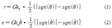
If θ is the angle of rotation of the driving pulley in anticlockwise direction, the torque that the driving pulley receives from the generator in anticlockwise direction. τ, and the potential difference between the two terminals of the generator, e, are given by Equation (1) and Equation (2) respectively.
where, θ &
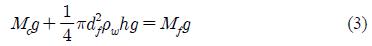
 is the angular velocity of the driving pulley, i, is the current flowing in the coil of the generator, sgn(x) = 1 for x > 0 and -1 for x < 0, G is the total gear ratio from the driving pulley to the generator, kt is the torque constant, ke is the induced voltage constant. Here, the term in the brackets multiplied by half describes the effect of ratchet mechanism. Equation (1) and Equation (2) indicate that the driving pulley receives an anticlockwise torque from the generator when the floater is falling. The left part of Figure 2 shows the position of the floater and the water surface at stationary condition without work and the right part shows their position at an arbitrary time when the system is working indicating the heave and the surge motions. Equation (3) represents the force balance at the stationary condition. Here, Mf : mass of the floater, Mc : mass of the counterweight, df : diameter of the floater, h : submerged height of the floater in this equilibrium and ρw : density of water.

Sketch of the partially submerged floater
The total fluid force acting on the cylinder has been calculated using the modified Morison’s formula as given below [1][2].
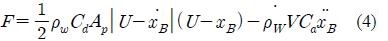
Where, Cd : drag coefficient, Ca : added mass coefficient, U : fluid velocity, xB : position of body with each dot representing its time derivative, V : submerged volume of the cylinder. Depending on the wave conditions and system dimensions, the floater will be either partially submerged, fully submerged or completely out of the water, necessitating that the mathematical model be able to respond to all these conditions as and when they arise. For simplicity, each of these conditions is dealt separately and corresponding equations are developed rather than prescribing a universal equation covering all the conditions.
When is Float Partially Submerged, the equation of floater motion in the vertical direction is given by
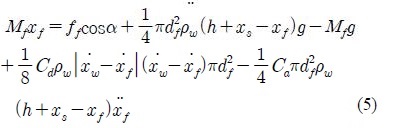
where, Hf : height of the float, Cd : drag coefficient, Cm : ( 1 + Ca), ff : tensile force in the cable supporting the float, xf, yf : vertical and horizontal displacement of the floater measured from the stationary free state as shown in Figure 3, xs : vertical displacement of the water surface, and xw , yw : vertical and horizontal displacement of the water particle.

Schematic of the float motion
2.3 Equations of the Driving Pulley Motion
The equation of the rotation of the driving pulley considering all other rotating components is as follows:
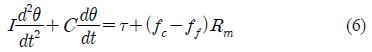
where, I: the mass moment of inertia of all the rotating bodies, C : viscous damping coefficient, Rm : radius of the driving pulley, fc : tensile force of the wire supporting the counterweight evaluated from Equation (1) and Equation (2) can be combined to write the torque as follows:
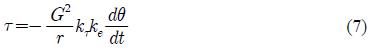
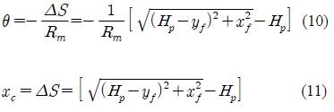
where, the expression e=i • r is applied, where r is the internal resistance of the generator. Equations (1), (2) and (7) need to be expressed in terms of the floater motion components xf and yf before combining with the equations of floater motion. From Figure 3, the change in the length of the wire, ΔS, from the stationary free state at any instant due to the horizontal and vertical motions of the floater can be written as
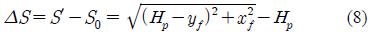
condition equal to , S′: length of the wire at any instant in operation. Thus, the angle between the vertical and the direction of the wire tension can be written as Equation (9).
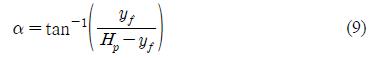
Finally, the angle of rotation of the driving pulley counterclockwise and the vertical displacement of the counterweight can be expressed as
3. Electrical power and the mechanical work rate of the wave energy system
3.1 Combination of equations
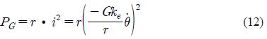
The expression for wire tension is obtained in terms of directional force. The differential equations are first rearranged so that each contains only one of the second order differential variables, then solved numerically using Runge-Kutta fourth order method to obtain the time series of the heave and surge displacements. Time series of the angle of rotation of the driving pulley and its derivative can now be calculated and used to estimate the electric power output from the following equation.
The mechanical work rate or power is calculated as the product of the wire tension and the velocity of the floater in the direction of the wire tension and is given as follows where W.R. stands for the work rate.

Here, we define the terms indicating the water motion in equations given by the linear wave wave theory which are used for calculations. The water surface elevation xs is given by for progressive waves with wave height H, angular wave number k and angular frequency. Then, by using the initial conditions the equations can be solved. Stationary free conditions of the floater are chosen as the initial conditions and are given.
3.2 Validation of wave energy conversion model
The floater descends rapidly during the subsequent lowering of the water level. This causes sharp and instantaneous fluctuations of the cable tension force which accelerates the wearing of the device components and the cable itself. In addition, a large fluctuation in the resulting mechanical work rate and the electrical power output is also observed since these quantities depend on the tension force. To avoid this situation, an energy storage device is combined with the floater-counterweight wave energy converter. Experimental results are given for the vertical motion of water in the water chambers for wave energy converter aligned along the wave propagation direction in order to avoid the impulsive wave forces.
4. Results and Discussion
4.1 Experimental test of wave energy
Experiments were conducted in an artificial wave tank. The wave tank used was 3.2 m deep, 30m wide and had an effective length of 160 m. At one side of the longitudinal direction was a wave maker and the model was set at the opposite side so that the floater received waves directly. Figure 4 shows the model set in the wave tank. Floaters were supported by idler pulleys mounted at an intermediate position of a beam supported by vertical columns.

Experimental setup
The experimental apparatus consisted of two pairs of floaters and counterweights with the dimensions specified in Table 1 The shafts rotate with the same speed everywhere but individual torques is accumulated at points where they are connected to the driving pulleys. Regular waves were produced and the clutch was turned on at some proper time when the wave crest reached the floaters. The water level, heave and surge displacements, pitch and roll angles, speed of the floater motion in the vertical direction, wire tensile force and torque were simultaneously measured. Wave period and wave heights for which experiments were performed are as follows: 1.8s/0.32m, 2.0s/0.25m, 3.0s/0.14m, 3.5s/0.24m, 4.0s/0.27m, 4.5s/0.15m and 5.0s/0.10m. Significant work rate was observed only for two conditions: 3.5s/0.24m, 4.0s/0.27m.

Dimensions for experiment
The present experiment was carried out using two circular floating cylinders each 2m in diameter. The center distance between the two floaters was 2.5 meters and the floaters were arranged normal to the wave direction. The ratio of the floater diameter to their spacing was 0.8. Spring et al. [3] have shown that the force on a cylinder is significantly affected by the presence of neighboring cylinders and their spacing. Experimental data for the added mass and drag coefficients have been presented by many authors for the surface piercing as well as no-surface piercing bottom fixed cylinders in the presence of interference from neighboring cylinders. But experimental data on the interference effects for multiple floating cylinders seem scarce. Charkrabarti [4] has determined the mass and drag coefficients of various numbers and spacing of vertical cylindrical tubes. The authors have used these data to interpolate the mass and drag coefficients for the current model calculations. For the two experimental conditions which gave a significant work rate (3.5s/0.24m, 4.0s/0.27m) as indicated in Table 2, the K-C numbers are respectively 0.54 and 0.44. Since these values are very close, the hydrodynamic coefficients are not expected to differ significantly.
Experimental conditions for significant energy conversion
Therefore only one set of Cm and Cd applicable for both experimental cases was determined. Mean curves of mass and drag coefficients against the K-C number for the case of two tubes with the spacing to diameter ratio of 1.25 presented by Chakrabarti [4] give Cm =3 and Cd =2.8. This shows that the inertia as well as the drag coefficient departs significantly from the conventional values due to the interference from neighboring cylinders.
4.2 Comparison of Experiment and Model Results
When wave period was shorter than 3 seconds, the device could not convert energy significantly due to the large pitching motion of the floaters. However for wave conditions 3.5s/0.24m and 4.0s/0.27m, significant work rate was observed on account of higher amplitude of heaving of the floater. The surge was much smaller than the heave at both conditions.
Figure. 5, 6 and 7 show the comparison between the calculated and experiment results for the time series of the heave and surge displacements of the floater, wire tension and the work rate of the device respectively.
These figures show that the model underestimates the heave and the surge by half and overestimates the wire tension. As for the work rate of the device, the model shows a fairly good agreement with the experimental results. All the figures show that the model gives a temporal variation of these quantities similar to the experimental results for them.

Time series of heave displacement

Time series of wire tension

Time series of work rate
4.2 Discussion for wave energy system
In this paper, the authors have proposed the dynamics model of the floater counterweight type wave energy converter which takes into account both the vertical and horizontal forces on the floater due to the water flow in wave condition. The model consists of the combination of the equations of the generator, force balance at stationary free-state, and equations of floater motion in operation and equation of the driving pulley motion. Finally, simultaneous second order differential equations for the vertical and horizontal displacements of the floater have been obtained. Vertical and horizontal components of the water particle velocity averaged over the floater submergence depth have been evaluated from the linear progressive wave theory in order to give the components of the force acting on the floater. The applicability of the model has been examined by comparing with experimental data which showed that the model underestimates the heave and surge displacements, overestimates the wire tension, and gives a relatively good agreement for the energy gain. This feature is the same as that for the author’s model which considered only the heaving motion of the floater.
5. Conclusions
We have conducted experiments with two floaters only and have used the results in this paper. It was found that though the calculated work rate was in good agreement with that of the experiment, it may have been caused by the cancellation of the overestimation of the wire tension and underestimation of the floater displacement. We plan to improve the calculation results by using more suitable fluid force coefficients.
This investigation has been planned as a fundamental step to examine the operational condition of the proposed device when it is set in front of the vertical harbor structure where standing wave occurs. The authors plan to conduct experiments with the device in such wave conditions in the future.
Acknowledgments
This research was financially supported by the “2013 Honam SeaGrant Project (Study on Oprimal Design for mooring equipment of Offshore Structure)” and “2012 broad economic leading industry development business(Interal and external equipment module plan and manufacturing technique development of medium-sized(50ft~70ft) leisure boat platform base)”
Notes
References
-
K. Hadano, K. Taneura, M. Watanabe, K. Nakano, . Saito, and M. Matsuura, “On the dynamics of the float type wave energy conversion”, Japan Society of Civil Engineers Journal B, 62(3), p270-383, (2006).
[https://doi.org/10.2208/jscejb.62.270]

-
J.. R Morison, M. P. O’Brien, J. W. Johnson, and S. A. Schaaf, “The forces exerted by surface waves on piles”, Journal of Petroleum Technology, American Institute of Mining Engineers, 2(5), p149-154, (1950).
[https://doi.org/10.2118/950149-G]
- B. H. Spring, and P. L. Monkmeyer, “Interaction of plane waves with vertical cylinders”, Proceedings of 14th International Conference on Coastal Engineering, American Society of Civil Engineers, p1828-1847, (1974).
- S. K. Chakrabarti, “Wave forces on multiple vertical cylinders”, Journal of the Waterway, Port, Coastal and Ocean Division, American Society of Civil Engineers, 104(2), p147-161, (1978).