The study on a ship energy management system applied rechargeable battery
Recently, the study of energy saving technology of ships begins in earnest, as energy saving policies are performed all around the world. SEMS (Ship Energy Management System) is one of the techniques to increase energy efficiency by applying to a independent system like a ship and offshore. SEMS is composed of Cooling Pump Control System (CPCS), Renewable Energy Emergency Power Control System (REEPCS), Load Control System (LCS), and Heating, Ventilation, and Air Conditioning System (HVACS). SEMS is enable to increase energy efficiency and achieve integrated management through the interlocking of each system. Especially, it is possible to improve the flexibility of the selection of the generator capacity in conjunction with a rechargeable battery and renewable energy. In this paper, SEMS applied rechargeable battery is proposed and simulated. By applying the rechargeable battery, it was confirmed that SEMS applied rechargeable battery can be operated at optimum efficiency of the generator.
Keywords:
Ship energy management system, Rechargeable battery, Efficiency of generators1. Introduction
For systems that make up the independent power system as ship, efficient use of energy is important. In recent years, due to environmental regulations to be strengthened and oil prices soaring, various technological developments have been made with the aim to improve the efficiency of ship operations and reduce operating costs. In particular, the International Maritime Organization (IMO) mandates the Ship Energy Efficiency Management Plan (SEEMP) in 2013. In future, it is considered that these environmental regulations will be further strengthened.
As a method for improving the energy efficiency of the ship, you can operate the generator at optimum load factor and manage the energy used by the auxiliary system. In the case of a ship, propulsion system is accounted for the highest load factor. In addition, load of auxiliary system such as lighting, heating and cooling system accounted for the next. In the case of vessels, such as cruise ships, because the proportion of the auxiliary system load is higher than the other ship, it is necessary to improve the efficiency through the monitoring and control. Generator of the ship exposes the best efficiency in the load factor of 85% of its capacity, but the potential for problems of safety hazards is high any more. For this reason, it is advantageous to operate the generator at 85% load factor as far as possible in order to increase the energy efficiency of the ship [1].
In this paper, the Ship Energy Management System (SEMS) including Load Control System (LCS), Renewable Energy Emergency Power Control System (REEPCS), Heating, Ventilating, Air Conditioning System (HVACS) and Cooling Pump Control System (CPCS) is proposed, and researched.
2. Structure of Ship Energy Management System
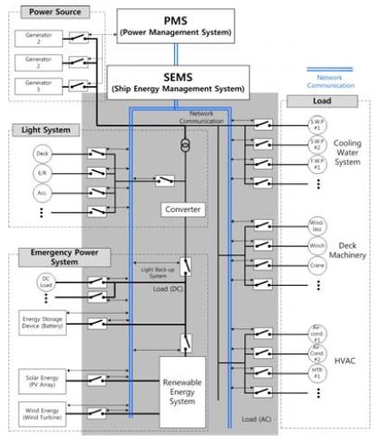
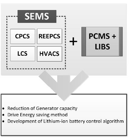
Ship Energy Management System (SEMS) linked with the Power Control Management System (PCMS) refers to technology that can reduce the energy, and assure the flexibility of power utilization and generation system. SEMS comprising Cooling Pump Control System (CPCS), Renewable Energy Emergency Power Control System (REEPCS), Load Control System (Load Control System) and Heating, Ventilation, and Air Conditioning System (HVACS) is intended to increase the operational flexibility of the power system rather than efficiency of the generator itself and the propulsion system of the ship. Figure 1 shows the components of the SEMS.
With integrated management of SEMS, linkage between individual systems like air conditioning system, seawater pump system, and generator system is possible. Further, by applying the renewable energy and the rechargeable battery, it would improve efficiency and reduce energy and carbon dioxide emissions of ships.
2.1 Cooling Pump Control System
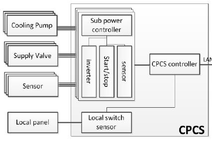
CPCS is a system to reduce power consumption by taking into account water temperature, and pressure, and controlling the flow of sea water and fresh water. CPCS is controlling RPM of the seawater pump and fresh water pump and a valve, on the basis of internal algorithms. Figure 2 shows schematic diagram of the CPCS.
CPCS is that system using an inverter and motor control technology to control pumps in response to environmental conditions, and it allows to save energy.
2.2 Renewable Energy Emergency Power Control System
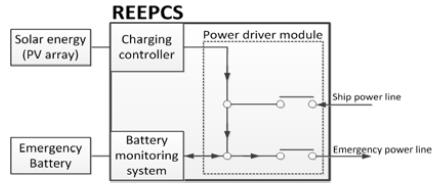
REEPCS is a system for managing the development of renewable energy. This is used in charging to emergency power supply or safety services [2]. And then the emergency battery is full, it can be reduced load of ship by using HVACS and light system. Figure 3 shows the schematic diagram of REEPCS [3].
2.3 Load Control System
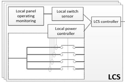
Heavy consumer such as Ballast pump, Crane, etc increases the number and capacity of the generator. LCS is a system to improve the efficiency of power operation linked with the PCMS to manage and operate the load that heavy consumer needs [4].
Through the control algorithm, LCS can manage the power system more efficiently and maximize energy savings. By measuring the various quantity of electricity and the change in the load, it is possible to improving safety and peak value control.
2.4 Heating, Ventilation, and Air Conditioning System
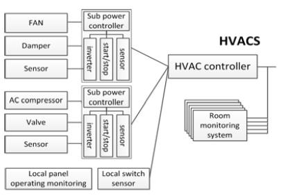
HVACS is a system that can be adjusted to the minimum power of Fan, Damper, and Unload system, by measuring the temperature and humidity inside and outside. And here, the algorithm working with the power system of the ship and changing the set temperature if necessary, are included.
3. Rechargeable battery linked SEMS
SEMS including CPCS, REEPCS, LCS and HVACS reduces unnecessary load on the ship operations and increases the efficiency of energy. Additionally, when building the SEMS of the rechargeable battery based, it is possible to prevent the rapid changed in generator load and improve the flexibility in the sizing of the generator. Figure 6 shows an overview of the SEMS applied the rechargeable battery.
Productivity of renewable energy since not constant, it is possible to improve the efficiency by connecting a rechargeable battery. Further, it is possible to manage the rapid changing heavy consumer by linking with LCS to control load of ship. For this to be possible, the control algorithm of the rechargeable battery must be included.
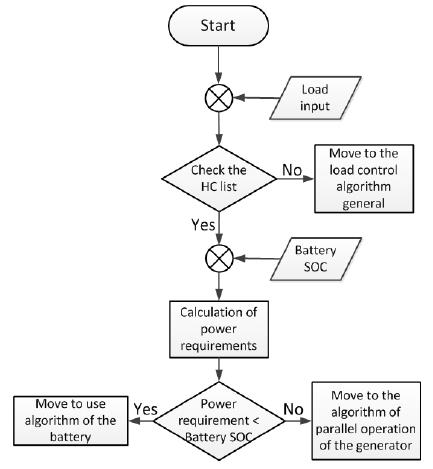
Because of the heavy consumer(like the bow thruster, ballast pump, etc), the capacity of the generator is chosen significantly. In the case of SEMS applied the rechargeable battery, it is possible to either reduce the number of the generator, and reduce the capacity of the generator. Figure 7 is a control algorithm of SEMS applied the rechargeable battery.
4. Simulation
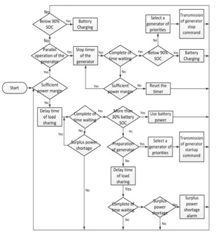
SEMS applied rechargeable battery has advantages that improve the efficiency of the generator by maintaining the optimum load, enhance the reliability by storing renewable energy has not uniform energy production, and prepare a sudden load change. The simulation is composed of the produced electricity from generator, renewable energy, propulsion load and auxiliary load that can be ON/OFF. And charging and discharging of the rechargeable battery takes place in accordance with the efficiency of the generator. The conditions of the simulation are shown in Table 1. LabVIEW has been used as simulation program. Figure 8 shows a flowchart of the simulation.
Figure 8 is an algorithm to calculate the surplus power and determine the parallel operation of the generator or use of the rechargeable battery. If the surplus power is sufficient, It can be determine the "stop generator" or "charging of rechargeable battery" according to the number of units in operation of the generator. If it is determined that single generator can afford all loss, parallel operation of generator will switch to independent operation of the generator[4]. Otherwise it will move to the charging algorithm of the rechargeable battery. In addition, when the single generator operating surplus power is generated, it will move to the charging algorithm of the rechargeable battery. Conversely, if surplus power is insufficient when the single generator is operating, it would be moved to discharge algorithm of the rechargeable battery. As a result, charge or discharge of rechargeable battery will be determined by SOC. If it is determined that SOC of the rechargeable battery is sufficient, the using rechargeable battery commands is transmitted, otherwise parallel operation command is transmitted. If both fail, free power shortage alarm is sent.
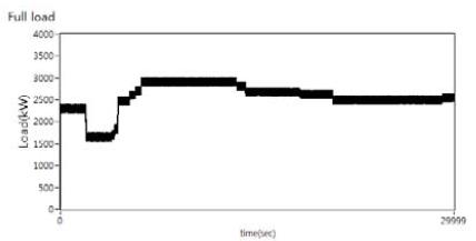
Figure 9 shows the change in the overall power consumption as a result of having been simulated on the basis of the conditions in Table 1.
In order to apply the rechargeable battery, and adjusted the load via the ON / OFF of the auxiliary loads. It is possible to confirm that the load changes between 1400kW to 3000kW.
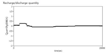
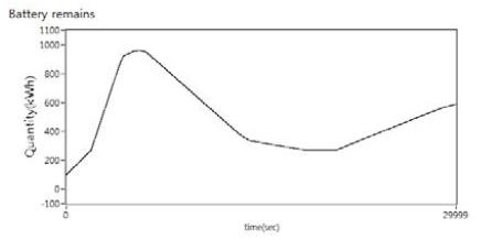
Figure 10 is a graph showing the power to be charged and discharged the rechargeable battery. Based on the load factor, charging and discharging are performed. In Figure 11, it is able to confirm that the charge amount of the rechargeable battery is increased or decreased depending on the charge and discharge amounts that shown in Figure 10.
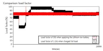
Figure 12 is a graph comparing the load factor to bear 1 generator if it does not apply to the case of applying the rechargeable battery. When applying the rechargeable battery, it can be confirmed that the load factor of the generator is kept constant at 85% or less. If the load on the generator did not reach 85%, by charging power to the rechargeable battery, so as to maintain a 85% load factor. When the load that 1 generator should bear is more than 85%, the rechargeable battery operates with generator, so it is sufficient to run only 1 generator. It is possible to prevent the low-load operation of the generator by such a mechanism, maintain the optimum load factor, and improve the efficiency of energy and the flexibility in the selection of the generator capacity.
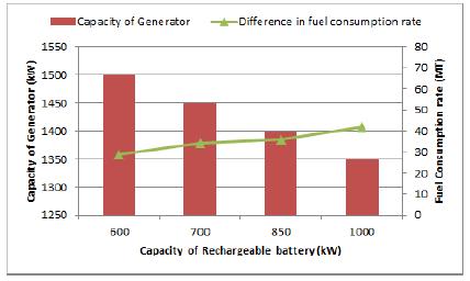
Figure 13 is a graph showing the difference in fuel consumption and capacity of the generator due to change in capacity of rechargeable battery witch is derived based on simulation and Specific fuel consumption curve[5]. The difference in fuel consumption rate means the difference between a fuel consumption rate of SEMS applied the rechargeable battery and a fuel consumption rate of conventional generator that does not use a rechargeable battery. Referring to the graph, when the capacity of the rechargeable battery increases, the difference in the fuel consumption rate increases and the capacity of the generator decreases. However, analysis for the economy is required for practical application, because of the high price of the rechargeable battery.
5. Conclusion
In this paper, SEMS applied the rechargeable battery is proposed and the simulation for this is done. Through SEMS applied the rechargeable battery, it is enable to reduce unnecessary load to the ship during operation, increase flexibility in the selection of the generator capacity, and improve the efficiency of renewable energy. In addition, it prevents rapid change of the load.
For the application of substantial SEMS applied the rechargeable battery, it is necessary to consider, such as the following. Basically, the capacity of the generator decreases the capacity of the rechargeable battery increases. However, because there is a problem of the price of the rechargeable battery, the studies to searching the optimal point between capacity of the generator and the capacity of the rechargeable battery should be proceeded.
Acknowledgments
This work is the outcome of a Manpower Development Program for Marine Energy by the Ministry of Oceans and Fisheries.
Notes
References
- M. Lappi, J. P. Jalkanen, and L. Johansson, “Effect of speed reduction on particle emissions of ships”, Journal of Clean Shipping Currents, 2(3), p1-6, (2013).
- Joo-Seok. Park, Seung-Ho. Hang, Chul Hee. Cho, Bo Yun. Jang, Hong-Soo. Kim, and Young-Soo. Ahn, “A study on renewable energy and the secondary battery-electricity storage technologies”, The Korean Solar Energy Society Conference Proceedings, p121-127, (2006).
- Battery Back-Up system, http://www.dcacpower.co.kr/other/AUTO.htm, Accessed Nobember 4, 2013.
- Standard Application Documentation Multi-Function System for Control and Protection of Generator Plants, TR-MARINE TECHNOLOGY, (2010).
- So-Yeon. Kim, Byung-Geul. Cho, and Seung-Ki. Sul, “Feasibility study of intergrated power system with battery energy storage system for naval ship”, IEEE, p532-537, (2012).
