Structural design and evaluation of a 3MW class wind turbine blade
This research presents results of structural designs and evaluations for 3MW Wind Turbine Blade by FEM analysis. After the GFRP model was designed as a baseline model, failure check by Puck’s failure criterion and buckling analysis were accomplished to verify safety of wind turbine blade in the critical design load case. Moreover, applicability of two kinds of carbon spar cap model, was studied by comparing total mass, price and tip deflection to the GFRP model. The results showed that the GFRP model had sufficient structural integrity in the critical design load case, and the carbon spar cap model could be a reasonable solution to reduce weights, tip deflections.
Keywords:
Wind turbine blade, Composite blade, Structural design, Structural analysis, Carbon spar cap1. Introduction
Recently, the development of common use wind turbine blades gradually becomes to be large with the reason of economics. The rotor blade that has been developed in 1980 was 15m rotating diameter, 30KW level. However, the recent prototype blade is more than 110m rotating diameter with 5MW capacity as a very large blade. The trend of large rotor blade is anticipated to be accelerated with the technology of offshore wind turbine technologies. The development of large blade was possible with the introduction of fiber reinforced plastics (FRP) manufacturing technologies from airplane and boat building. The initial prototype wind turbine blades were applied several materials such as steel, metal, and wood and the several designs have been considered. However, through performance test, the mechanical characteristics and economics including weights and fatigue characteristics have been decided to be worse than FRP (Fiber Reinforced Plastics) blade. And now, most large rotor blades use the universal FRP stressed skin design [1]. This design has the structure of sustaining most weights at the skin of the blade and it is a structure of having one or two shear webs inside of the blade to sustain the shear loads. Moreover, GFRP (Glass Fiber Reinforced Plastics) is often used for the blade material and infusion process which impregnates resin to fabric by vacuum is often applied for the manufacturing process [2]. Recently, the common use wind blade is somehow standardized like explained above about design, material, and manufacturing process. However, through the development trend of large wind turbine, new design, material, and manufacturing process are sought. Example for that, high quality and lightweight blades are manufactured by applying carbon fiber which has more excellent fatigue characteristics, high specific strength and high specific stiffness than glass fiber and automatic processes were introduced to lessen the labor in wind turbine manufacturing company [3][4].
In this research, structural design about 3MW “all GFRP model” was accomplished as a baseline model and structural integrity evaluations were performed by applying ultimate design loads. Moreover, the comparison of mass, price, tip deflection between “all GFRP model” and “carbon spar cap model” was accomplished to study the applicability of carbon spar cap model.
2. Design specification and load case
In this research, 3MW wind turbine blade model that has been designed by BEM (Blade Element Momentum theory) has been applied. The design specification is indicated at Table 1. The blade length is 45.5m, and the electrical power is 3MW considered the losses of drive train and generator [5].
DLC (Design Load Case) 2.1, which is the condition of control system failure of wind turbine, was applied as wind loads. The ultimate load calculation was performed by a commercialized aero-elastic analysis code, GH-Bladed v.4.0, considering all the possible situations during life time in accordance with the Technical Guidelines for Wind Turbines [6][7]. Moreover, structural analysis was accomplished by applying derived ultimate load from the system load calculations.
3. Structural design
3.1 Selection of blade materials
Material selection is one of the important things in blade structural design process and should be considered first. The reason is that the manufacturing process and design of wind blade largely depend on me chanical, physical and chemical properties of used materials and that design should also be changed by used materials. Uniaxial and triaxial fabrics were applied in the blade design of this research as reinforcement and the balsa wood was applied as the core material to increase the buckling resistance. Moreover, the epoxy type of gel coat was used to reinforce the surface with environmental degradations such as moisture absorption, ultraviolet rays, and erosion.
Infusion process was selected as manufacturing process. The process has excellent price competiveness and good mechanical properties than other manufacturing processes of composite blade. Material properties of applied GFRP and CFRP laminate during structural design are indicated in Table 2.
3.2 Lay-up pattern
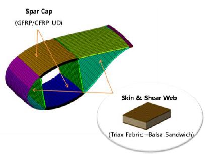
The composites wind blade that this research designed is the stressed skin design that sustains the load from blade skin like Figure 1 indicates and it is a structure with coupled web. Moreover, to sustain the bending moments and torsion moments to blade length direction, reinforced the stiffness by designing spar cap on the location of 15~50% of total chord length. At the outside of blade, material to protect the skin from the environment is ordinarily laminated and fiber-reinforced composites to sustain the load from the wind are laminated at the inside.
The layer for skin protection in Table 3 corresponds to number 1 and 2. The gel coat has been laminated to protect skin from degradation due to operation of the blade and the random mat has been laminated to have durability of little skin damage. Layer number 3~5 are composed of sandwich structure and laminating structure of form core or uniaxial glass fabric inside the triaxial glass fabric [10].
3.3 Spar-cap material
Recently in developed turbine manufacturing company, applies some in blade with carbon fiber that is possible to have lighter design and more excellent fatigue characteristic than the glass fabric.
And as the blade gradually becomes larger, the concern about the weight has been issued and to solve this issue, application of the reinforcement like carbon fabric which can lessen the weight than the existing design by the material is required [11]. UD glass and UD carbon fabric is applied as reinforcement of spar cap in this research and three different models of material in spar cap part have been structured and designed (Table 4).
3.4 FE-Modeling and design verification
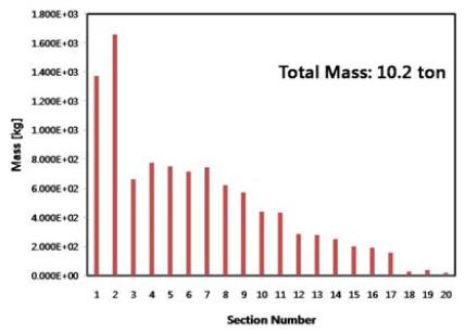
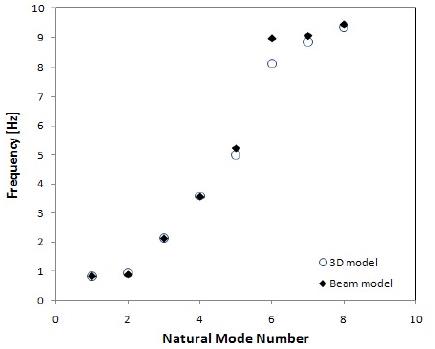
A finite element model of the blade was modeled by shell element, and the model was laid-up by using the lay-up pattern as shown in Table 3. The finite element model of the rotor blade was generated as a quad type mesh with about 9541 nodes and 9942 elements, and the material properties of Table 2 were used for generating the 3-D FE-model. The ANSYS-ACP was used as pre-processor for structural analysis of layered composite structures, and the fixed degrees of freedom boundary condition was applied on the end of blade root. The structural analysis was carried out using ANSYS Workbench. Indicated the weight distribution by section about “all glass design” in Figure 2 and confirmed the total weight, around 10.2 ton. Since this kind of structural design result should be provided with initial input in aero-elastic analysis of beam model, it is required to confirm whether the three dimension model is implemented as beam model or not. For this kind of design verification, the comparison of natural frequency between three dimensional and one dimensional model was performed. Indicated the result in Figure 3 and after comparing two models, even though the unique frequency was little different when it goes to higher, confirmed that the equivalent model was appropriately implemented.
3.5 Acceptance criteria
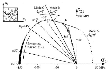
By applying the composite failure criterion of Puck’s failure criterion, confirmed the FF (Fiber Failure) and IFF (Inter Fiber Failure) and indicated the boundary of IFF damage decision by τ21 (shear between resin and fabric) relation for σ2 (resin stress direction) in Figure 4. To draw this graph, it is need to know the stress (resin direction and shear of resin and fabric), failure mode of A, B and C, and fracture angle. It implemented this part at common use structure analysis software with base of suggested equation from Puck [12]. Moreover, it performed the failure analysis by applying the applied material properties of safety factor (FF:2.205, IFF:1.764) in technical guideline of Korean Register of Shipping during the structural design.
4. Structural analysis result
4.1 Strength analysis result of GFRP blade
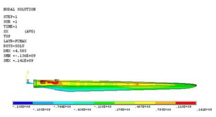
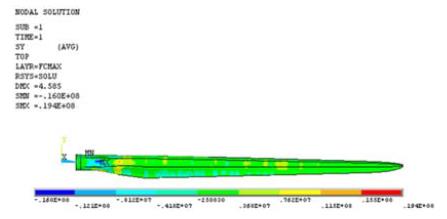
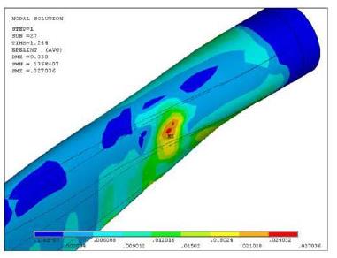
Blade stress and strain distributions were calculated by static analysis and the results in Figure 5~7 and Table 5. First, the stress distribution appeared to be high on blade longitudinal direction and, especially, it was able to confirm the high value of spar cap near blade root and leading Edge. It is because that the blade model is designed to sustain most of loads at skin. Therefore, the selection of material and lay-up pattern is really important in the structural design.
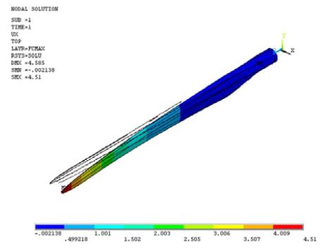
Moreover, through the result of strain contour indicated in Figure 6, it was able to confirm that there were deflections of 4.51m at the blade tip.
Confirmed whether there was failure in FF and IFF by the part by applying Puck’s failure criterion and indicated the result in Table 6. As you see the table, FF and IFF Criteria indicated criteria numerical value less than 1 and can know that no failure occurred in all part of the blade. Moreover, implemented high value in skin section for FF and shear web and spar cap for IFF. However, since the failure between fabrics do not directly affect to the structural safety of the blade, there will be no need for changing the structural design like increasing number of lamination. Rather, it is required to decrease the number of lamination excluding the shear web.
4.2 Buckling analysis result of GFRP blade
Linear and non-linear buckling analysis was accomplished by applying the ultimate load, and buckling stability was evaluated by the analysis results. The results were summarized in Table 7. The table shows that load factors of linear and non-linear buckling were exceeded ultimate load, and all load factors had the margin of more than 20%. Therefore, the designed blade has sufficient buckling stability under wind loads.
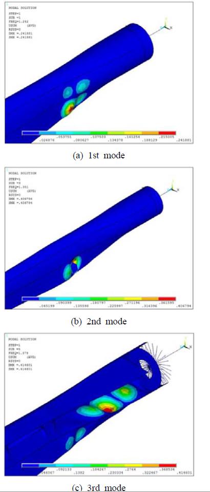
Figure 8 shows linear buckling shape of 1st, 3rd, and 5th mode. Buckling of 1st, 3rd mode was observed at spar cap, trailing edge, and that of 5th mode was shown at shear web. Moreover, linear buckling was occurred at the inboard section of blade.
Non-linear buckling analysis was accomplished by using mode shape of 1st mode shape. Figure 9 shows the shape of non-linear buckling, and the buckling was appeared at spar cap of the blade inboard section. In conclusion, it is thought that enhancing buckling strength at inboard section of wind turbineblade is one of the important things by using core materials. Also, it is worth considering new materials at skin of inboard section to reinforce stiffness of wind turbine blade.
4.3 Analysis result of carbon spar cap blade
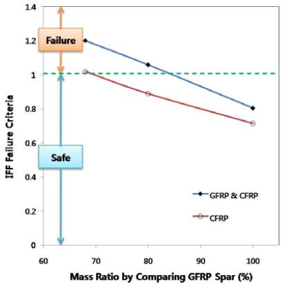
To inquire the possibility of applied model of UD carbon fabric in the section of spar cap, changed the structural design in spar cap part of existing “all glass design”. Moreover, to implement appropriate number of lamination in spar cap part of the two models, designed the 100%, 80%, and 68% models about the weight of “all glass design” and implemented the number of lamination in spar cap part through the result of IFF Criteria. From the behaviors of hybrid blade (GFRP & CFRP) and CFRP in Figure 10, the minimum mass ratios by comparing GFRP spar cap were calculated. Moreover, two kinds of carbon spar cap model were designed by using the mass ratios.
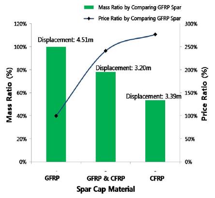
In Figure 11, indicated the weight, price, and tip deflection of blade of three models. All results are indicated as ratio of “all glass model”. First, the weight of hybrid spar cap was 78% of GFRP spar cap and the weight of CFRP spar cap was 53% of the spar cap that is designed as GFRP. Moreover, the price, with the standard of GFRP spar cap, of hybrid spar cap was 270% and of CFRP spar cap was 240%.
The tip deflection of the blade was 4.51m of GFRP spar cap, 3.20m of hybrid spar cap, and 3.39m of CFRP spar cap. From here, we confirmed that hybrid spar cap has less tip deflection than CFRP spar cap. The reason was that the standard of selecting a number of lamination was IFF Criteria value which is decided by strength but the tip deflection relates with stiffness. So this kind of aspect could be happened.
Through this result, the carbon spar cap is 2.7 times more expensive than the glass fabric spar cap. But the weight can be lighter, deflection is less, and the fatigue characteristic is relatively excellent. So, it is possible to apply by the design target specification of blade. Moreover, it could be a good choice to apply new blade materials, such as S-2 glass fabric because their material properties and price is between E-glass and Carbon.
5. Conclusion
From this research, structural design and analysis of 3MW wind turbine blade was accomplished by FEM analysis and the result can be summarized as follows.
(1) Through the comparison of natural frequency between three dimension model and one dimensional beam model of “all glass design”, it was confirmed that the equivalent property of the one dimension model was properly implemented and it was able to provide the accurate needed initial input for the load analysis.
(2) After the structural design of “all glass design”, confirmed that the failure of FF and IFF did not occur through Puck’s Criterion and were able to know that blade has enough structural safety.
(3) There was no buckling failure in the blade under the designed wind loads, and the margin of limit loads were more than 20%. Therefore, we could concluded that the blade have sufficient buckling resistant under wind loads.
(4) After changing the material of spar cap part, with the standard of GFRP spar cap, the weight and the price of hybrid spar cap were 78% and 240% and the weight and the price of CFRP spar cap were 53% and 270%. Through this, we were able to know that carbon spar cap is more expensive than GFRP spar cap. But the light design was possible. Moreover, the carbon spar cap design can be applied by the initial design standard and, to solve the issues of the weight of large blade in the future, application of materials, such as carbon or S-glass fabric is required.
References
- E. Hau, and Wind. Turbines, 2nd ed., Berlin, Germany: Springer, (2006).
- Gurit Wind Energy Handbook - 2, Wind Turbine Blade Structural Engineering, http://www.gurit.com/wind-energy-handbook-1.aspx, Accessed December 29, 2013.
- H. C. Lin, “Lay-up analyzing of a Carbon/Glass hybrid composite wind turbine blade using finite element analysis”, Applied Mechanics and Materials, 87, p49-54, (2011).
- H.-J. Bang, “Smart structure technologies for offshore wind turbine”, Proceedings of the KOSME 34th Fall Conference, p71-72, (2010), (in Korean).
-
B.-S. Kim, W.-J. Kim, S.-Y. Bae, J.-H. Park, and M.-E. Kim, “Aerodynamic design and performance analysis of Multi-MW class wind turbine blade”, Journal of Mechanical Science and Technology, 25(8), p1995-2002, (2011).
[https://doi.org/10.1007/s12206-011-0521-x]

- Korean Register of Shipping, Technical Guidelines for Wind Turbines, Seoul, Korea: Korean Register of Shipping, (2008), (in Korean).
- GL-GarradHassan, GH-Bladed 4.10. User's Manual. GL-GarradHassan, (2011).
- S.-H. Lee, K.-S. Cho, and J.-S. Park, “Structural analysis and verification test of 3MW wind turbine blade”, Proceedings of the KWEA Fall Conference, p36, (2009), (in Korean).
-
K. K. Wetzel, “Defect-tolerant structural design of wind turbine blades”, Proceedings of the EWEA Annual Conference, p1, (2009).
[https://doi.org/10.2514/6.2009-2409]

-
T. Burton, N. Jenkins, D. Sharpe, and E. Bossanyi, Wind Energy Handbook, West Sussex, UK: John Wiley & Sons, (2011).
[https://doi.org/10.1002/9781119992714]

-
P. Jamieson, Innovation in Wind Turbine Design, West Sussex, UK: John Wiley & Sons, (2011).
[https://doi.org/10.1002/9781119975441]

-
A. Puck, and H. Schurmann, “Failure analysis of FRP laminates by means of physically based phenomenological models”, Composites Science and Technology, 62, p1633-1662, (2002).
[https://doi.org/10.1016/S0266-3538(01)00208-1]


