Separation characteristics of particles in a self-rotating type centrifugal oil purifier
The centrifugal oil purifier is used in an engine for lubrication and to remove impurities. The momentum needed for the rotation of the cylindrical chamber is obtained by jet injections. An impure particle in the oil is separated by the centrifugal forces moving to the inner wall of the rotating cylindrical chamber body. The dust particles are eliminated when the particles are absorbed onto the surface of the inner wall of the chamber body. The flow characteristics and the physical behaviors of particles in this centrifugal oil purifier were investigated numerically and the filtration efficiencies was evaluated. For calculations, a commercial code is used and the SST (Shear Stress Transport) turbulence model has been adopted. The MFR (Multi Frames of Reference) method is introduced to consider the rotating effect of the flows. Under various variables, such as particle size, particle density and rotating speed, the filtration efficiencies are evaluated. It has been verified that the filtration efficiency is increased with the increments in the particle size, the particle density and the rotating speed of the cylindrical chamber.
Keywords:
Centrifugal Oil Purifier, Filtration Efficiency, Impure particle, CFD (Computational Fluid Dynamics), MFR (Multi Frames of Reference)1. Introduction
The extension of life expectancy of oil is of paramount importance due to rise in oil prices. As a result, the role of purifier is critical. An oil purifier is one of the key components in diesel engines. Generally, FO (Fuel Oil) purifier, LO (Lubrication Oil) purifier and system oil filter are widely used to maintain clean conditions of marine engines.
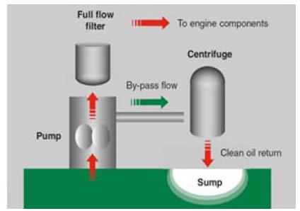
Figure 1 shows a schematic diagram of the circulation system of oil lubrication[1]. Most purifiers use the full flow filter. This filter – belonging to the element type – cannot purify the sub-micron sized matters present in oil. In order to purify such matters the pore size should be reduced in conventional filters. However, this produces large pressure drop which eventually makes oil circulations worse in the main lubricating lines. To overcome this problem, a centrifugal oil purifier is used which takes about 10% of the total circulating oil from the main circulation system for purification.
Several studies on the centrifugal type filters have been carried out. Jeong [2] carried out a study on the standard criteria of solid particle separation test for marine centrifugal purifier. Lee and Kim [3] carried out a basic study on the integrated lubrication system for large scale marine diesel engine in terms of the lubrication efficiencies. Kim et al. [4] studied on the enhancements of filtration efficiencies of centrifugal purifiers in case of gas-liquid two phase flows. Bang et al. [5] evaluated the flow characteristics and the filtration efficiencies of a cylindrical centrifugal purifier for the case with simple inlet and outlet conditions. Smiles [6] investigated the centrifugal filtration of particulate systems by numerical analysis method. Most of the researches have focused on the cases having simple inlet and outlet conditions not having actual using conditions. A commercial code Ansys CFX is used for calculation purposes [7].
The purpose of this study is to investigate the flow characteristics within the centrifugal oil purifier and the movement of impurities for the case of actual using conditions. Moreover, the effects of number of blades, particle density, particle size and rotating speed of the filter have also been investigated in terms of filtration efficiency.
2. Numerical Analysis
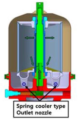
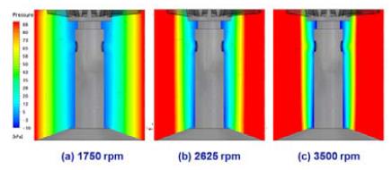
Figure 2 shows the cross sectional view of a centrifugal oil purifier. The oil comes in from the inlet at the upper part of the rotating shaft and it goes out via the outlet at the lower part. The oil inside the purifier is accelerated with the centrifugal force and the impurities are separated from oil due to inertia of their mass and moves toward the inner surface of the rotating cylinder, and are, lastly accumulated at the wall of the purifier where a sheet of paper filter is installed. The centrifugal force is produced by the rotational moments which are generated by injecting oil via two nozzles installed at the lower part of the purifier.
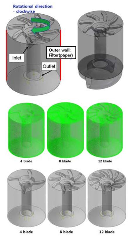
Figure 3 shows the calculation domain for the analysis. The grid system, the tetrahedral mesh are used and the prism layer has been constructed for the wall side. The number of the grids is 700,000 cells. In this study, three types of blade models - 4-blade, 8-blade and 12-blade models - are tested.
The physical properties of the operating oil tested (SAE 30) are:
temperature 90℃, density ρ = 853.9kg/m2 and viscosity μ = 0.0356kg/x·m.
The SST (Shear Stress Transport) turbulence model is used due to its known superior standards and its reliability to model flows having higher shear stresses. To analyse the rotational effects of the flow fields, the function of MFR (Multi Frames of Reference) is applied and the equilibrium equation for the force acting on the particles is represented by the Lagrangian coordinate system given by Equation (1) which was derived by Basset, Boussinesq and Oseen for a rotating reference frame.
Here,
FD = drag force acting on the particle [N]
FB = buoyancy force due to gravity [N]
FR = forces due to domain rotation [N]
FVM = added mass force [N]
FP = pressure gradient force [N]
FBA = Basset force or history term [N]
To calculate the particle movements, flow field analysis was performed first. From the results obtained, the motions of the discrete particles were predicted based on the phase model in which the behaviour of particles are calculated. The interactions between the dust particles and the working fluids have been neglected in this study because the particle sizes are too small to influence the working fluids. The forces on the particle are calculated from the pressure gradients. The number of used grids for calculation is decided on the condition that there is no grid dependency. The validation for the numerical simulation is now being tested experimentally for the next research reports.
3. Results and Discussion
The filtration efficiency is defined by the ratio of the particle numbers filtered over the total particle numbers inserted into the purifier. Accordingly, the filtration efficiency can be described by Equation (2).
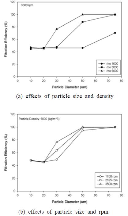
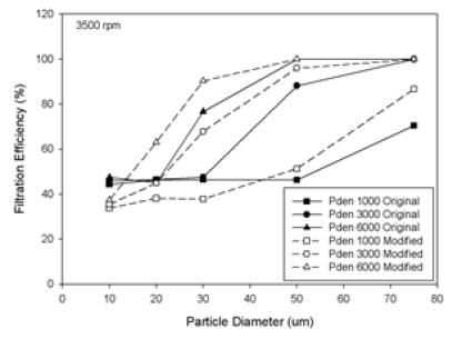
Figure 4 (a) shows the filtration efficiency according to the density and size of the particle. Under high density of particles, the filtration efficiency is higher and at low density, the filtration efficiency is limited.
This can be inferred from Equation (1) that the radial force due to the buoyancy force (FB) becomes larger than the tangential force due to the drag force (FD).
In case of the particle density ρ=6000 kg/m3, the efficiency begins to increase at the size of 30μm. In case of the particle density ρ=1000 kg/m3, the efficiency begins to increase at the size of 75μm. Figure 4 (b) shows the filtration efficiency according to the rotation speed (rpm) and the size of the particle. The efficiency increases with increments in rotating speed. At the particle's size 30μm, the efficiency showed large differences in accordance to the rotating speed. When the particle's size is bigger than 50μm and is smaller than 20μm, the efficiencies do not show any dependency on the rotating speed. This implies that the blades installed near the upper cover induce the flow to upper radial direction, and the particles in the flow travel along the outer wall of the rotating chamber, and they are lastly eliminated by being attached upon the filter paper.
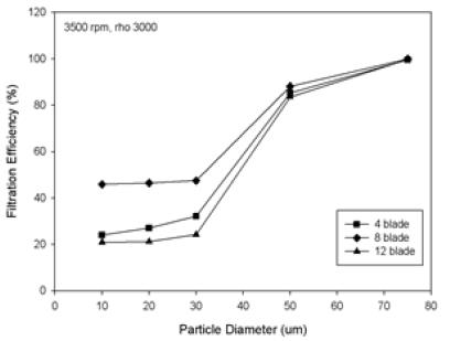
Figure 6 shows the effect of the number of blades to the filtration efficiency under the condition of 3500 rpm and ρ=3000 kg/m3 of particle density. In case of the 8-blade, the highest efficiency is seen among the three cases for all particle sizes. However, the differences of the efficiencies become small over the size 50μm, which implies that the effects of the blade number to the efficiency is not seen any more over a certain number of blades. This sort of result can be found in the studies on the centrifugal pumps. According to the studies done by Oztekin et al. [8] and Stepanoff et al. [9], the optimal number of blades is 5 to 9 for the centrifugal pumps.
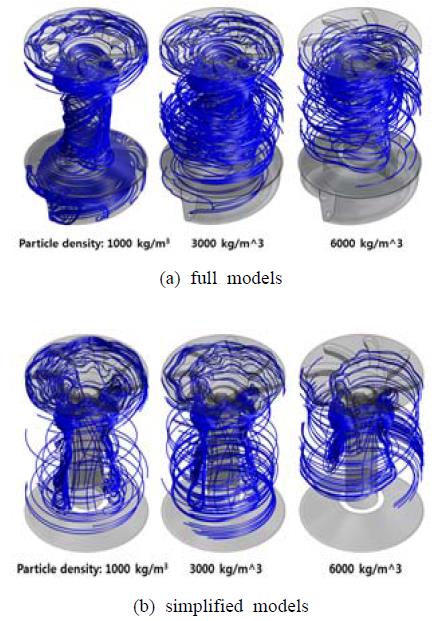
Particle tracking for various particle density of 8 blade model at 3500 rpm for Simplified model and full model
Figure 10 shows the particles' (impurity matters) movements for the three cases of blades. It can be seen from the figure that the particles are moving nearest to the outer wall of the cylindrical chamber in case of 8-blade, which implies the highest filtration efficiency.
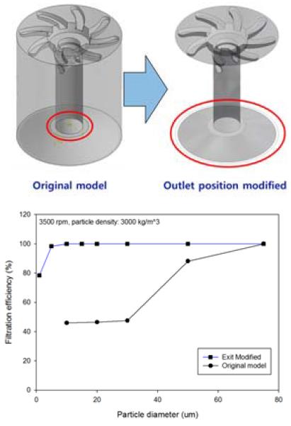
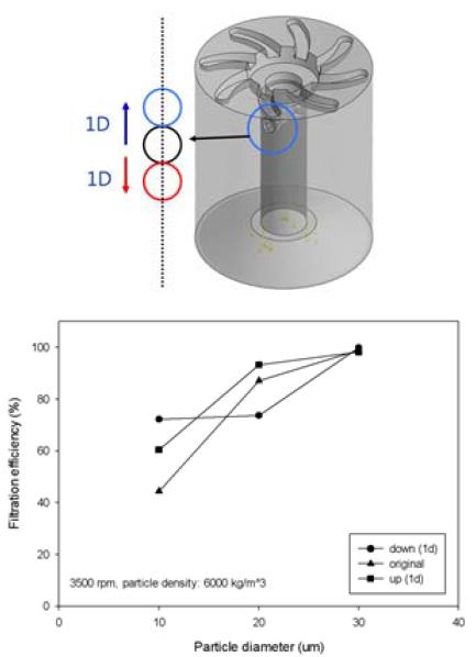
Figure 7 and 8 show the filtration efficiency along the various conditions(changing the exit position and inlet heights).
For the case of changing the outlet position to outer wall, the filtration efficiency is higher than the inside exit position (Figure 6) and filtration efficiency increases as the inlet heights increase.
In this study, the simplified model is used because only the quantitative comparison along the various conditions are required. But, both the simplified and the full models were used for a detailed investigation of design parameter. Figure 9 shows the flow characteristics of the full model and Figure 10 shows the filtration efficiency along the two models. The value of filtration efficiency is a bit different, but the pattern is similar.
For the case of changing the outlet position to outer wall, the filtration efficiency is higher than the inside position exit (Figure 7) and filtration efficiency increases as the inlet heights increase.
In this study, the simplified model is used because only the quantitative comparison along the various conditions are required. But, both the simplified and the full models were used for a detailed investigation of design parameter. Figure 9 shows the flow characteristics of the full model and Figure 10 shows the filtration efficiency along the two models. The value of filtration efficiency is a bit different, but the pattern is similar.
4. Conclusion
The characteristics of fluid flow and the physical behavior of the dust particles in various type of centrifugal oil purifiers have been numerically investigated by using CFD simulations to estimate the filtration efficiencies.
The removal efficiency of impurities increases when the particle size and its density increases. For a particle size of 50μm and density of 6000 kg/m3, the removal efficiency is approximately 10 % higher when compared to the particle size of 50μm and density of 3000 kg/m3. In particular, for a particle density of 1000 kg/m3 and particle size of 50μm, the removal efficiency is 60% higher. When the particle size is 30μm, the RPM increases and hence the particle removal efficiency increases by 15%. Also, when the particle size is more than 50μm, the particle removal efficiency is approximately 95 to 100%. When the particle size is between 10 ~ 30μm, blade 8 has twice the removal efficiency than blades 4 and 12. Moreover, when the outlet is positioned on the exterior of the wall, the removal efficiency increases by 50% and when the inlet is placed on top of the original model, the removal efficiency increases by 20%.
Acknowledgments
This work was supported by a Research Grant of Pukyong National University (2013).
Notes
References
- MANN+HUMMEL GMBH, Business Unit Industrial Filters. J. H. https://www.marn-hummel.com/fileadmin/user_up_load/service/cat alogues/pdf/MH_Centrifuges_en.pdf, Accessed August 13, 2013.
-
S. H. Jeong, “A study on the standard criteria of solid particle separation test for marine centrifugal purifier”, Journal of the Korean Society of Marine Engineering, 31(8), p1028-1034, (2007), (in Korean).
[https://doi.org/10.5916/jkosme.2007.31.8.1028]

- I. Y. Lee, and J. W. Kim, “A basic study on the integrated lubrication system for large scale marine diesel engines”, Spring Conference of the Korean Society for Power System Engineering, p262-266, (2003), (in Korean).
- J. M. Kim, J. H. Lee, Y. K. Yoon, and H. D. Kim, “A study of the performance improvement of a centrifugal separator for gas-liquid two-phase flow”, Proceedings of the Korean Society of Mechanical Engineers Spring Annual Meeting, p3352-3357, (2007), (in Korean).
-
K. H. Bang, K. K. Kim, Y. A. Song, and P. S. Kim, “Numerical analysis of fluid flow and filtering efficiency in centrifugal oil filter”, Journal of the Korean Society of Marine Engineering, 33(6), p867-872, (2009), (in Korean).
[https://doi.org/10.5916/jkosme.2009.33.6.867]

-
D. E. Smiles, “Centrifugal filtration of particulate systems”, Chemical Engineering Science, 54, p215-224, (1999).
[https://doi.org/10.1016/S0009-2509(98)00229-2]

- Ansys CFX Release 11.0 manual, ANSYS Inc, (2006).
-
A. Oztekin, B. R. Seymour, and E. Varley, “Pump flow solution of the Navier-Stokes equations”, Studies in Applied Math, 107, p1-41, (2001).
[https://doi.org/10.1111/1467-9590.1071176]

- A. J. Stepanoff, Centrifugal and Axial Flow Pumps (Theory, Design and Application), KriegerPubCo, (2007).
