Synchronization and identification of ship shaft power and speed for energy efficiency design index verification
The maritime sector is advancing with dedicated endeavor to reduce greenhouse gas in addressing issues with regards to global warming. Since 01 January 2013, the International Maritime Organization (IMO) regulation mandatory requirement for Energy Efficiency Design Index (EEDI) has been in place and should be satisfied by newly-built ships of more than 400 gross tonnage and the Ship Energy Efficiency Management Plan (SEEMP) for all ships type. Therefore, compliance to this necessitates planning during the design stage whereas verification can be carried –out through an acceptable method during sea trial. The MEPC-approved 2013 guidance, ISO 15016 and ISO 19019 on EEDI serves the purpose for calculation and verification of attained EEDI value. Individual ships EEDI value should be lower than the required value set by these regulations. The key factors for EEDI verification are power and speed assessment and their synchronization. The shaft power can be measured by telemeter system using strain gage during sea trial. However, calibration of shaft power onboard condition is complicated. Hence, it relies only on proficient technology that operates within the permitted ISO allowance. On the other hand, the ship speed can be measured and calibrated by differential ground positioning system (DGPS). An actual test on a newly-built vessel was carried out to assess the correlation of power and speed. The Energy-efficiency Design Index or Operational Indicator Monitoring System (EDiMS) software developed by the Dynamics Laboratory-Mokpo Maritime University (DL-MMU) and Green Marine Equipment RIS Center (GMERC) of Mokpo Maritime University was utilized for this investigation. In addition, the software can continuously monitor air emission and is a useful tool for inventory and ship energy management plan. This paper introduces the synchronization and identification method between shaft power and ship speed for EEDI verification in accordance with the ISO guidance
Keywords:
Energy Efficiency Design Index (or Operational Indicator), Shaft Power, Ship Speed, Synchronization, Ship Energy Efficiency Management Plan, Monitoring System1. Introduction
The maritime sector is advancing with dedicated endeavor to reduce greenhouse gas that contributes to global warming. Addressing this, the Marine Environmental Protection Committee-International Maritime Organization (MEPC/IMO) contemplated in improving the energy efficiency and reducing fuel consumption in the view of reducing air pollutants. Hence since 01 January 2013, the IMO regulation mandatory requirement for Energy Efficiency Design Index or Energy Efficiency Operation Index (EEDI or EEOI) have been in place and should be satisfied by newly-built ships of more than 400 gross tonnage and the Ship Energy Efficiency Management Plan (SEEMP) for all ships type. Therefore, compliance to this necessitates planning during the design stage whereas verification can be carried –out through an acceptable method during sea trial. The MEPC-approved 2013 guidance, ISO 15016 and ISO 19019 on EEDI serves the purpose for calculation and verification of attained EEDI value. Individual ships EEDI value should be lower than the required value set by these regulations [1][2].
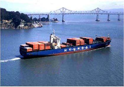
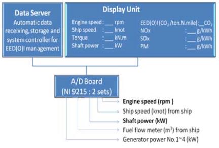
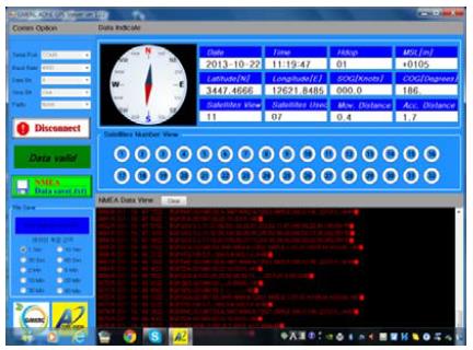
This paper introduces the synchronization and identification method between shaft power and ship speed factors for EEDI verification in accordance with the ISO guidance. The shaft power can be measured by telemeter system using strain gage during sea trial. On the other hand, the ship speed can be measured and calibrated by differential ground positioning system (DGPS). However, shaft power calibration is complicated due to onboard condition and relies entirely on proficient technology that operates within the permitted ISO allowance. An actual test on an existing vessel, as seen in Figure 1, and a container vessel were carried out to verify the correlation of power and speed synchronization. During the investigation, the Energy-efficiency Design Index (or Operational Indicator) Monitoring System (EDiMS) software developed by the Dynamics Laboratory-Mokpo Maritime University (DL-MMU) and Green Marine Equipment RIS Center (GMERC) of Mokpo Maritime University was utilized. Figure 2 illustrates the system and display configuration. The software likewise can continuously monitor air pollution and is a useful tool for inventory and ship energy management plan.
2. Ship power and speed measurement
2.1 The EDiMS Software
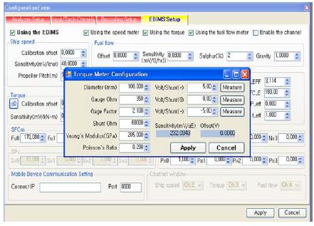
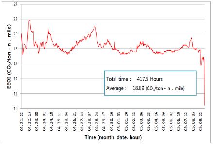
The IMO mandatory requirement on EEDI/EEOI verification should be carried-out through an acceptable method. With this necessity, the EDiMS software was developed by the DL-MMU. Other than its prime function of constantly monitoring the exhaust emission volume, the software can also monitor the engine operation output data [3]. Figure 3 shows the set-up configuration of the software wherein the output power and speed measurement using analog signal can be done simultaneously [4][5]. Figure 4 is the output data for the EEOI value verification for the test vessel.
2.2 Ship Power and Speed Measurement
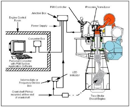
Different methods can be applied for engine power measurement. The pressure mean indicator, or Pmi as shown Figure 5, measures each individual cylinders pressure. However, the consistency of the mean shaft power value can be affected by external parameters such as changing sea state condition or fluctuating speed. Additionally, the ITTC defined the acceptable measurement devices, being torsion meter with strain gauges or calibrated permanent torque sensor having a bias error of 1%, for shaft power data measurement [6].
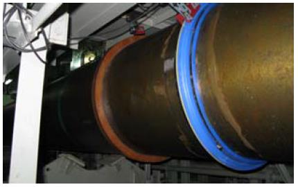
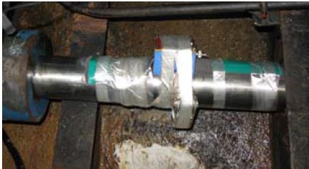
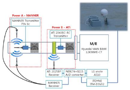
Figure 6 and Figure 7 pictures the telemeter system with strain gauges installed on the intermediate during the shaft power measurement. On Figure 6, two telemeter systems were installed to ensure the redundancy of the measured shaft power data. Figure 7 shows the capability of installing the telemeter system on smaller shaft diameter
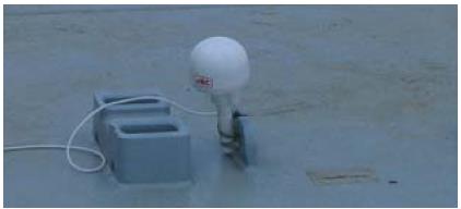
For ship speed measurement, likewise, data can be acquired implementing different methods. The Doppler Effect ship speed indicator can be utilized for the speed signal. In the absence of speed signal, ship speed can be estimated using the shaft rpm and the propeller shaft assuming there is no slip. For the purpose of EEDI verification, the use of global positioning system operated in differential mode must be used in the speed measurement. The analog signal generated by the DGPS transponder provides additional accuracy of measurement data. Figure 8 illustrates the DGPS transponder mounted during actual speed measurement. Figure 9 describes the EDiMS software shaft power – ship speed measurement configuration. Shaft stresses are obtained by the strain gauges and transmitted into the portable computer for computation of generated shaft power. The transmitted signals from the telemeter system and the DGPS speed sensor both passes through an A/D converter.
3. Synchronization between shaft power and ship speed measurement
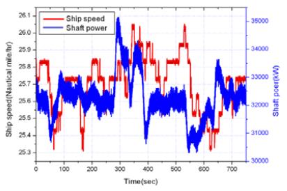
This paper investigates the synchronization of shaft power and ship speed for EEDI verification. The vessel’s deadweight, speed deviation, power peak value and sampling time effect on the synchronization process are presented in this paper. Specifically for minimizing the random peak value using the Chauvenet’s criterion, this paper presents analysis using root mean square to determine the mean value. On Figure 11, the correlation of shaft power and ship speed is illustrated. Ideally, similar deviation pattern will be followed by these two parameters.
ISO regulation for EEDI verification applies to all ships of more than 400 gross tonnages. However, taking into the account the vessels deadweight, there will be a big difference in its response to external factors such as sea condition, wind condition among others resulting to bigger deviation in its speed data and original track. This deviation should be considered to identify its effect in the synchronization of shaft power and ships speed.
Firstly, the ship’s position is denoted by the latitude and longitude and its course represented by an imaginary straight line. When the ship deviates from this course, EEDI verification accuracy can be affected. Thereby, synchronization of shaft power and ship speed should include the relationship of latitude and longitude to the ship’s position including its deviation.
The meridian distance on the sphere, m(ϕ), formula is given in Equation 1 wherein R is the mean radius of the Earth and ϕ is latitude angle. With this, the meridian length of 1 degree of latitude on the sphere is 111.2 km or 1.853 km for 1 minute of latitude.
As latitude is defined through an ellipsoid and the position of a given point is different on each ellipsoid, it is necessary to identify how the latitude and longitude values transforms from one ellipsoid to another. The shape of an ellipsoid of revolution is determined by the shape of the ellipse requiring two parameters, the equatorial radius and inverse flattening. The WGS84 ellipsoid, which is used for all GPS devices, defines the value for equatorial radius and inverse flattening. Thereby, there should be a definite reference datum identified, such as WG84, to be adopted in the synchronization of EEDI factors. Further, the distance from the equator to the pole is 10001.966km but when the latitude difference is 1 degree, corresponding to π/180.0radians, the arc distance can be calculated by
Using Equation 2, the variation in the distance between each degree of latitude can be compared while Equation 3 shows the length of a degree of longitude while earths’ eccentricity is denoted by e[7][8].
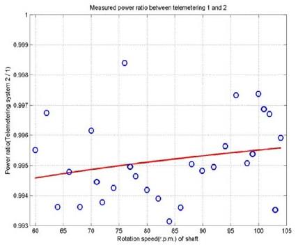
Secondly, the ITTC recommended the need for filtering the measurement data to minimize the “spike” or the random peak value using the Chauvenet’s criterion. Chauvenet’s criterion is a procedure of eliminating processed data if its acquired value is below or beyond the standard deviations [9]. Figure 12 is the ratio of measured power values from two telemetering equipment. These values should be evaluated to confirm the reliability of the measuring equipment adhering to the recommended bias error smaller than 1% [10].
The EDiMS software is capable of processing measured data both on raw and filtered status. Comparison of previous power and speed data analysis for both raw and filtered condition yielded an almost negligible deviation hence confirming the capability of the EDiMS program to disregard the “spikes” in its data analysis. Further, it is hypothesized that the Chauvenet’s criterion of time domain is not fully applicable to torque measurement due to perceived higher deviation value output. Hence, new methodology on speed and shaft power mean value calculation using the root mean square of frequency domain is introduced and integrated on the program. Mean value deviation applying the Chauvenet’s criterion (σc) can be given as Equation 4 while the maximum deviation is assumed at ± 3σc. The root mean value correction (σr) is given in Equation 5 wherein the Tai is the torque variable value through FFT analysis peak from 1st order to 12th order for two stroke diesel engine including electric propulsion system and from half order to 12th order for four stroke diesel engine based on shaft rotating speed including the propeller blade order. Accordingly, the maximum deviation is assumed to be ± 3σr .
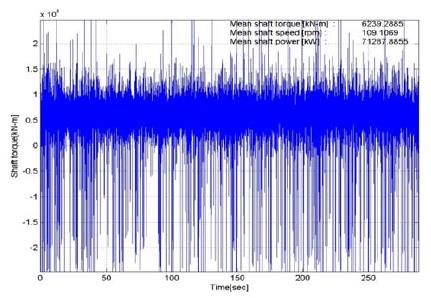
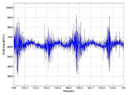
In reference to Figure 12, the shaft power measurement data between the two telemetering system were analysed and compared. Measurement data for telemetering equipment B were further analysed applying the Chauvenet’s criterion and FFT analysis method. Likewise, both equipment measurement data were evaluated using the moving filter technology. Figure 13 is the measured raw signal of equipment B in Figure 9 for shaft power.
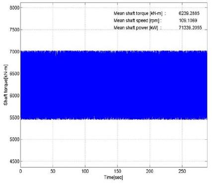
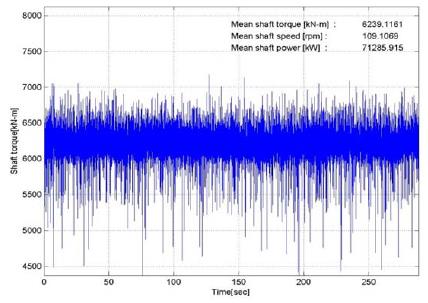
As mentioned beforehand, strain gauge telemetering system will yield high precision measurement data for shaft power and torque calculation. On the other hand, the increase in the shaft’s diameter will contribute to the increase or abnormality of the “spike” or the random peak value. The torque variable value estimation using FFT analysis method is commonly accepted while the sampling rate is increased to 2048/sec [11][12]. Figure 14 and Figure 15 show the shaft power calculation using FFT analysis and the sampling time data respectively.
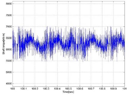
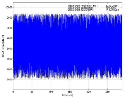
Figure 16 and 17 is the shaft power measurement analysis implementing the Chauvenet’s criterion. The Chauvenet’s criterion data is mainly based on the time domain signal; hence the evidence of random peak value or “spikes” as can be seen on Figure 16. Figure 17 is the zoomed out illustration for the shaft power data at 2048/sec sampling rate using Chauvenet’s criterion. The moving filter analysis method is likewise carried-out on this paper. Moving filter approach is based on analysing stored data, in this case 40 data, wherein the process is carried out as new data is acquired while dropping off one previously stored data. Figure 18 is the illustration of the corrected shaft power measurement using the moving filter technology.
Table 1 overview the analysis result for each telemetering equipment and calculation method applied. The test engine was run at 109.2 rpm and measurement data were simultaneously gathered using the two telemetering equipment. For telemetering equipment A, the value deviation between raw data and moving data is almost negligible. On telemetering equipment B, three shaft power calculation methods were carried out. Comparison to the raw data, value deviation yielded 0.26%, 0.07% and zero-deviation for Chauvenet’s criterion, FFT and moving filter method respectively. From this result, application of FFT method on identifying the shaft power mean value is more reliable and accurate as it can eliminate better the random peak values compared to the Chauvenet’s criterion.
On Figure 19 and 20, the speed deviation for the small coastal vessel was measured on different sea state condition. For Figure 19, sea current condition was observed and the deviation between the DGPS generated speed and actual speed is about 0.147kt. For the same direction of sea current, as seen on Figure 20, the calculated deviation is 0.374kt. The big deviation difference shows the effect of external factors influence to lower tonnage ships, hence the reduced accuracy on shaft power – ship speed relationship.
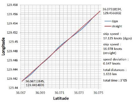
Deviation of ship speed test round 1 for small coastal vessel with the sea current at opposite direction
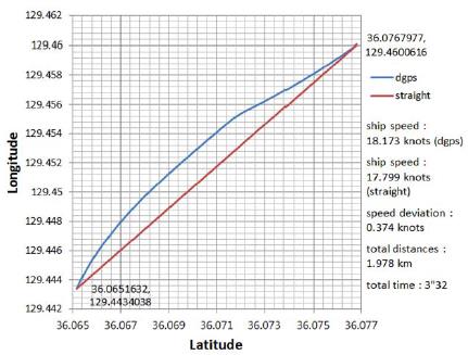
Deviation of ship speed test round 2 for small coastal vessel with the sea current at same direction
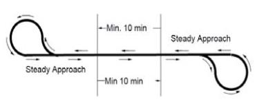
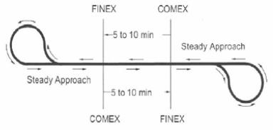
Under the IMO guidance for speed – power measurement, the minimum sampling time is at least 600secs at constant condition as can be seen on Figure 21[13]-[16]. Constant condition refers to load settings and external factors such as sea conditions. Considering this, lower tonnage vessels are more dependent on external factors. Hence, the longer the sampling time acquisition, the accuracy of measurement data is being reduced. Figure 22 is the recommendation of Marine Research Institute Netherlands (MARIN) shortening the sampling time acquisition from 5minutes to 10minutes. The Dynamics Laboratory of Mokpo National Maritime University suggests a data sampling time acquisition of at least 180secs or defining a sampling time for each vessel tonnage range pending future studies.
4. Conclusions
This paper presented the synchronization of shaft power and ship speed for EEDI verification. The EDiMS software designed by the DL-MMU was utilized for this purpose.
1. It is recommended for EEDI or EEOI verification to use an integrated equipment and compact software capable of measuring the shaft power and ship speed simultaneously. This is seen to be more advantageous in shaft power – ship speed synchronization. Additionally, analog signal also improves the measurement accuracy compared to digital signal. EDiMS software features this capability and available for application.
2. New methodology on speed and shaft power mean value calculation using the root mean square method based on FFT analysis is introduced and integrated on the program. Comparison of calculated shaft power mean value result using Chauvenet’s criterion and FFT RMS method indicated a smaller deviation value for the latter. Implementing this methodology on shaft power – ship speed synchronization is seen to give the higher reliability and accuracy in identifying the shaft power mean value compared to the Chauvenet’s criterion method.
3. ITTC recommendation covers all ships of more than 400 gross tonnages. However, lower tonnage vessels are susceptible to higher measurement data deviation due to external factors influence. Reducing the data sampling acquisition is perceived to increase the measurement data accuracy and reduce analysis deviation.
4. EDiMS can measure shaft power using strain gauge from small diameter shafts (99mm) to biggest propulsion shaft diameter and applicable also to higher speed engines.
Acknowledgments
This paper is supported by the Ministry of Oceans and Fisheries and the Green Marine Equipment RIS Center of Mokpo National Maritime University
References
- IMO MEPC59/INF.10, Second IMO GHG Study 2009 Update of the 2000, (2009).
- IMO MEPC55/4/8, Information about indexing trials according to the Interim Guidelines for Voluntary Ship CO2 Emission Indexing, (2006).
-
R. Barro, J. Kim,, and D. Lee, “Real time monitoring of energy efficiency operation indicator on merchant ships”, Journal of the Korean Society of Marine Engineering, 35(3), p301-308, (2011).
[https://doi.org/10.5916/jkosme.2011.35.3.301]

- Don Choo Lee, Kie See Joo, Tak Kun Nam, Eun Seok Kim, and Sang Hwan Kim, “Development of integrated vibration analysis and monitoring system for marine diesel engines and ship machineries”, 26th International Council on Combustion Engine, Paper No. 65, (2010).
- D. C. Lee, K. S. Joo, T. K. Nam, E. S. Kim, and S. H. Kim, “Development of engine vibration analysis and monitoring system (EVAMOS) for marine vessels”, Transactions of the Korea Society for Noise and Vibration Engineering, 19(2), p155-162, (2009).
- H. Boom, van der I. Hout, and M. Flikkema, “Speed-power performance of ships during trials and in service”, Proceedings of The Society of Naval Architects and Marine Engineers, (2008).
- www.wikipedia.com, Accessed September. 10 2013.
- J. August, “Simple statistics for laboratory data analysis”, American Biltrite, Inc, (2001).
- IMO MEPC 64/INF.6, Speed/power trials, part 2, analysis of speed/power trial data, (2012).
- ISO 20383-2, Mechanical vibration – Measurement of vibrations on ships, Part 2. Measurement of structural vibration, (2008).
- ISO 20383-4, Part 4. Mechanical vibration – Measurement and evaluation of vibration of the ship propulsion machinery, (2012).
- C. Klimt-Møllenbach, Green ship of the future, Available: www.greenship.org, (2010).
- ISO 3046-1, Reciprocating internal combustion engines – Performance- Part 1. Standard reference conditions, declarations of power fuel and lubricating oil consumptions, and test methods, (2001).
- ISO 15016, Ships and marine technology ― Guidelines for the assessment of speed and power performance by analysis of speed trial data, (2002).
- ISO 19019, Sea-going vessels and marine technology ― Instructions for planning, carrying out and reporting sea trials, (2005).
- IMO MEPC61/5/2, Report on a trial verification of energy efficiency design index (EEDI), (2010).
