디스크 레이저를 이용한 순 타이타늄의 비드용접시 비드색에 따른 용접특성
2Staff, R&D Center, Laser Line, Tel: 031-427-1780 shpark@laserline.co.kr
3Researcher, Department of Marine Engineering, Korea Maritime and Ocean University, Tel: 051-410-4676 mksong@kmou.ac.kr
Copyright © The Korean Society of Marine Engineering
This is an Open Access article distributed under the terms of the Creative Commons Attribution Non-Commercial License (http://creativecommons.org/licenses/by-nc/3.0), which permits unrestricted non-commercial use, distribution, and reproduction in any medium, provided the original work is properly cited.
초록
본 연구에서는 최대 출력 3.3 kW의 연속 출력 파형 디스크 레이저를 사용하여 순 타이타늄 용접을 실시하였다. 타이타늄은 용접시 고온에서 산소, 질소, 수소 및 탄소 등의 침입형 원소와의 반응성이 매우 높으므로 산화 및 질화에 대한 취성영역이 형성되어 용접부의 내식성과 기계적 성질을 저하시킬 수 있다. 따라서 최적의 실드가스를 선정하기 위하여 실드가스의 종류를 변화시켜 실험을 실시하였으며 그에 따른 용접성을 평가하였다. 비드색에 따른 용접부에 대하여 광학현미경 및 주사전자현미경을 이용하여 미세조직을 관찰하였다. 또한 경도측정을 통해 기계적 특성을 파악하였다. 용접부가 산화 또는 질화될 경우 비드표면에 덴드라이트 형상의 조직이 관찰되었으며 비드표면뿐만 아니라 용접부 내부까지 산소 및 질소량이 증가하여 경도값이 모재 대비 3배 이상 크게 증가하였다. 결과적으로 비드색에 따라 용접부의 미세조직, 기계적인 특성 등이 달라짐을 알 수 있었다.
Abstract
In this study, pure titanium welding was performed using a continuous output waveform disk laser with a maximum output of 3.3 kW. Titanium is highly reactive with interstitial elements such as oxygen, nitrogen, hydrogen and carbon at a high temperature during welding, and thus a brittle region is formed owing to oxidation and nitridation, which may deteriorate the corrosion resistance and mechanical properties of the welded portion. Therefore, in order to select the optimal shield gas, experiments were conducted by varying the type of shield gas and the weldability was evaluated. The changes in the microstructures of the welds with respect to the bead colors were examined using an optical microscope and a scanning electron microscope. The mechanical properties were also determined by performing a hardness measurement. When the welds were oxidized or nitrided, a dendritic structure was observed on the surface of the bead. The oxygen and nitrogen content increased not only on the bead surface but also inside the weld, resulting in an increase in the hardness value of more than 3 times that of the base metal. As a result, the microstructure and mechanical properties of the welds were found to vary depending on the bead color.
Keywords:
Pure titanium, Laser welding, Disk laser, Shield gas, Flow rate, Oxidation키워드:
순 타이타늄, 레이저 용접, 디스크 레이저, 실드가스, 유량, 산화1. 서 론
항공 및 자동차 등 수송분야에서 경량화 및 환경문제에 대한 솔루션으로 타이타늄 합금에 대한 수요가 꾸준히 증가하고 있다[1]-[3]. 따라서 타이타늄에 대한 여러 가지 용접기술이 개발되어 왔으며 최근에는 레이저 용접 기술에 대한 연구가 활발히 이루어지고 있다. 레이저 용접은 기존의 아크용접대비 입열량이 적으므로 용접열변형이 적으며 작은 용접부위에 대해 매우 정밀한 용접이 가능하다[4]-[11].
디스크 레이저는 독일에서 개발되어 이테르븀(Yb)이 도핑된 Yb:YAG 의 얇은 디스크를 매질로 하며 1,030 nm 파장의 광을 방출한다. 매질이 로드 타입인 레이저에 비해 디스크 레이저는 빔 품질이 우수하여 널리 사용되고 있다[12][13].
타이타늄은 고온에서 산소, 질소, 수소 및 탄소 등의 침입형 원소와의 반응성이 높으므로 용접부를 대기로부터 차폐하기 위한 적절한 실드조건이 필요하다. 이러한 반응을 통해 산화막이 생성되면 산화막 두께에 따라 비드색깔이 금색, 갈색, 청색 등으로 다양하게 변화하게 된다[14]. 따라서 비드색으로 산화정도를 파악할 수 있으므로 용접부의 특성을 대략적으로 판별할 수 있다.
본 논문에서는 디스크 레이저를 이용한 타이타늄 용접 시 실드가스 종류 및 유량을 변화하여 실험을 진행하였으며 비드색에 따른 용접성을 파악하고자 한다.
2. 실험 장치 및 방법
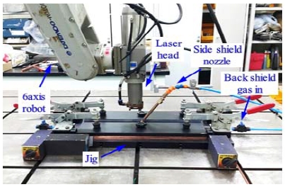
본 실험에 사용된 재료는 성형성 및 연성이 우수한 순 타이타늄(grade1)을 사용하였으며, 시험편의 크기는 50 mm(가로 )X 150 mm(세로 )X 0.5 mm(두께)이다. 재료의 화학적인 조성을 Table 1에 나타낸다. 용접 전에 시험편 표면을 메탄올로 세정하여 시편 표면의 이물질을 제거하였다. 본 실험에 사용된 레이저 열원은 최대 출력 3.3 kW, 연속 디스크 레이저이며 빔 품질(BPP)은 8 mm·mrad로 우수한 특성을 가진다. 실험에 사용된 레이저 용접 장치 구성모습을 Figure 1에 나타낸다. 레이저 집광광학계를 6축 외팔보 로봇에 장착하여 용접실험을 수행하였으며 전면비드의 실드는 광학계헤드에 장착된 직경 8 mm의 사이드 노즐을 사용하였다. 실드가스 종류에 따른 실험에서는 이면비드는 지그 홈에 순도 99.99%의 일반 아르곤 10ℓ/min를 사용하여 실드하였으며, 전면비드에 순도 99.99%의 일반 아르곤 및 질소와 순도 99.999%의 고순도 헬륨 3가지 실드가스를 적용하여 실험하였다. 전면실드의 경우 유량을 25ℓ/min으로 동일하게 하였으며 실드가스 종류에 따른 영향을 서로 비교하여 평가하였다.
3. 실험결과 및 고찰
3.1 실드가스 종류에 따른 용입특성
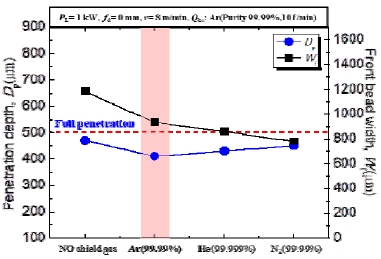
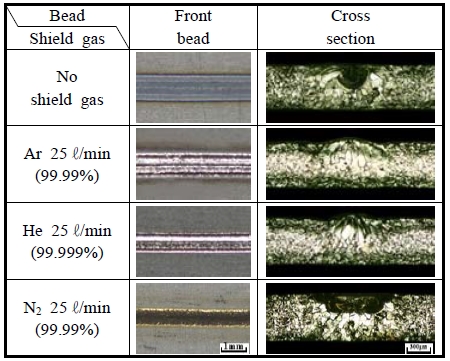
레이저 출력 및 용접속도는 용입특성을 파악하기 위하여 부분 용입이 되도록 선정하였으며 용입특성 그래프와 전면비드 및 횡단면의 사진을 Figure 2와 Figure 3에 나타낸다. 전면비드폭은 대기중에서 용접한 경우 산화에 따른 열로 인해 가장 넓게 나타났으며, 아르곤과 헬륨을 사용한 경우에는 대기로부터 용접부를 차단하여 비드폭이 좁아졌다. 실드가스로 아르곤을 사용한 경우 전면과 이면 비드에 모두 광택을 가진 은백색의 건전한 비드를 얻을 수 있었다. 순도 99.999%의 고순도 헬륨을 실드가스로 사용한 경우에도 은백색의 건전한 전면비드를 관찰할 수 있었다. 반면, 실드가스로 질소를 사용했을 때에는 전면비드에서 광택이 없는 검은색의 조악한 비드를 관찰할 수 있었다.
아르곤 및 헬륨과 비교하여 질소를 실드가스로 사용했을 경우에는 용입이 더 깊게 나타났다. 이는 용접시 용융부에 질소가 혼입됨에 따라 그 부분의 열전도율이 감소하게 되고 더 많은 레이저 빔의 에너지가 재료에 흡수되었기 때문으로 판단된다.
따라서 실드가스로서 일반 아르곤 및 고순도 헬륨을 사용하였을 경우 모두 광택이 있는 은백색의 건전한 비드를 얻을 수 있었으며 가격이 저렴한 일반 아르곤으로도 충분한 실드가 가능하기 때문에 순도 99.99%의 일반 아르곤을 최적의 실드가스로 선정하였다.
3.2 실드가스 유량에 따른 용입특성
본 실험에서는 3.1절에서 도출한 결과를 적용하여 전면실드에 동일하게 일반 아르곤을 사용하고 실드가스 유량(Qcs)을 변화하여 유량에 따른 영향을 평가하였다.
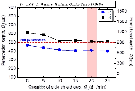
실드가스 유량에 따른 용입특성 그래프와 전면비드 및 횡단면의 사진을 Figure 4와 Figure 5에 나타낸다. 실드가스 유량이 0~ 5ℓ/min일 경우, 전면 비드폭이 증가하였다. 이는 실드가스의 유량이 부족하여 용접부를 대기로부터 효과적으로 보호하지 못했기 때문으로 판단된다. 유량이 10ℓ/min이상일 경우에는 유량에 관계없이 전면비드폭이 비슷한 경향을 나타내었다. 전면비드를 관찰해보면 비드색은 유량이 0~5ℓ/min일 경우 산화되어 회색을 나타내었으며 실드가스를 사용한 경우에는 금색 또는 은백색을 나타내었다. 비드형상은 유량 10~15ℓ/min까지 용접비드가 불균일하고 험핑비드가 관찰되었지만 유량이 20ℓ/min이상에서는 전체적으로 은백색의 건전한 비드가 관찰되었다.
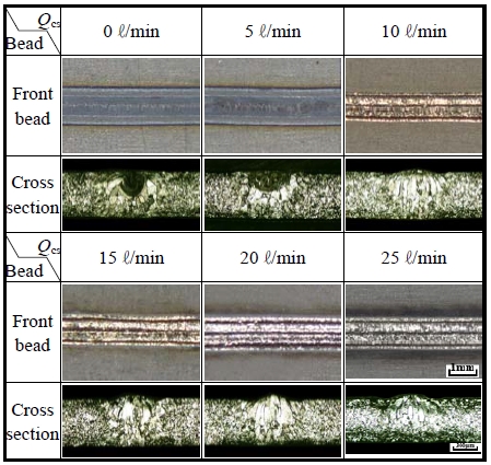
Penetration properties and various bead shapes with flow rate of shield gas (fd = 0 mm, PL = 1 kW, v = 8 m/min)
따라서 유량이 20ℓ/min일 경우 비드색이 은백색을 나타내고 건전한 비드를 나타내었기 때문에 향후 실험에서 순도 99.99%의 일반 아르곤 20ℓ/min를 전면실드가스로 사용하였다.
3.3 비드색에 따른 용접부의 미세조직 및 경도특성
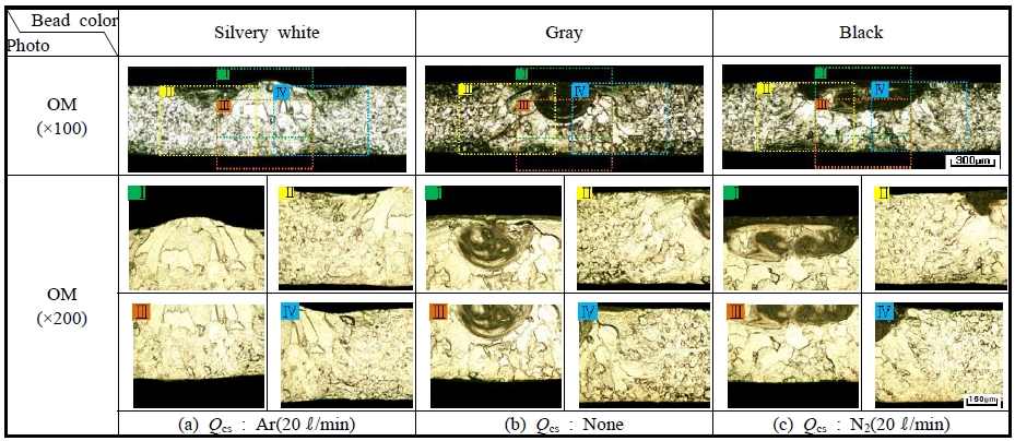
레이저 용접변수 레이저 출력 1 kW, 용접속도 8 m/min의 동일한 조건에서 실드가스 종류를 변화하여 다양한 비드색의 용접부를 얻을 수 있었다. 은백색 및 금색의 비드는 아르곤 실드조건에서, 회색은 대기 중, 검은색의 경우는 질소가스 실드 조건에서 각각 얻을 수 있었다. 이 때 질소가스 실드조건은 아르곤 실드조건과의 비교를 위하여 유량을 20ℓ/min로 동일하게 선정하였다. 광학현미경을 이용하여 용접부를 관찰한 사진을 Figure 6에 나타낸다. 은백색의 비드의 경우 조대한 주상정이 나타났으며 이는 불순물이 없는 타이타늄의 특징으로 생각된다. 회색 및 검은색의 경우, 비드 상부의 조직이 어둡게 관찰되었다.
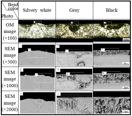
주사전자현미경을 이용하여 용접부를 관찰한 결과를 Figure 7에 나타낸다. 은백색의 비드 상부에서는 광학현미경결과와 마찬가지로 조대한 조직이 관찰되었으나 회색 및 검은색의 비드표면에서는 덴드라이트 형상의 조직이 관찰되었다. 검은색의 비드의 경우 이러한 조직이 더 두드러지게 관찰되었다. 이는 용접부 상부에 산화 또는 질화로 인한 산화물 및 질화물로 판단되며 EDS를 통해 추가적인 분석을 실시하였다[15].
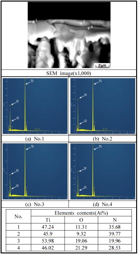
EDS를 이용하여 은백색, 회색 및 검은색 비드의 용접부 상부를 분석한 결과를 각각 Figure 8 ~ Figure 10에 나타낸다. 은백색비드의 경우 산소와 질소 함량이 각각 8~14 wt%, 0~0.9 wt%로 상대적으로 적게 나타났다. 회색 비드의 경우에 최상부 어두운 부분이 산소함량이 매우 높고 질소는 검출되지 않은 것으로 보아 산화층으로 판단된다. 이 부분은 추후에 XRD분석 등을 통해 추가적인 분석을 진행할 예정이다. 검은색 비드의 경우에는 질소함량이 상부에서 하부로 내려갈수록 감소하는 경향을 나타내었으며 질소를 실드가스로 사용하여 산소를 차단하였는데도 불구하고 산소함량이 비교적 높게 나타났다. 이러한 결과는 타이타늄이 질소보다 산소와 반응성이 높기 때문에 산소량이 적음에도 불구하고 산소와 쉽게 반응했기 때문으로 판단된다.
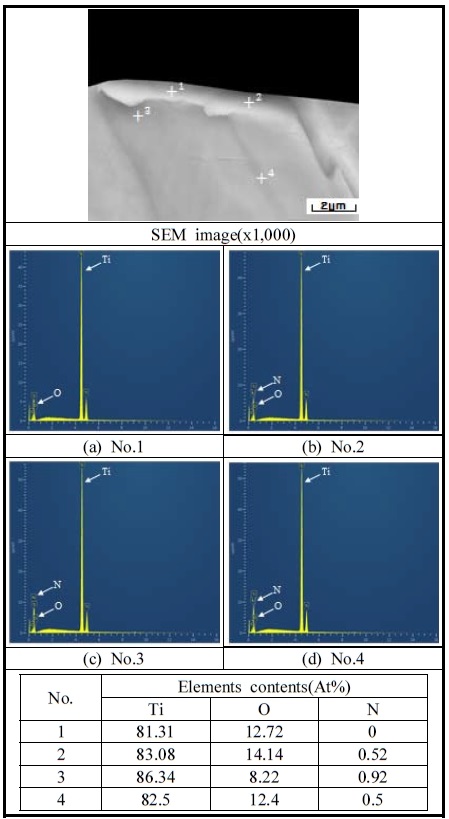
Results of EDS analysis of near top surface zone of silvery-white bead color (fd = 0 mm, PL = 1 kW, v = 8 m/min)
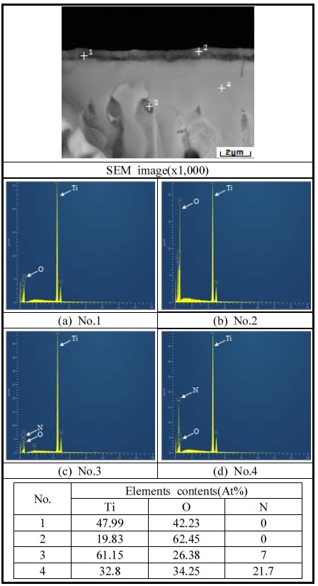
Results of EDS analysis of near top surface zone with gray bead color (fd = 0 mm, PL = 1 kW, v = 8 m/min)
3.4 비드색에 따른 경도특성
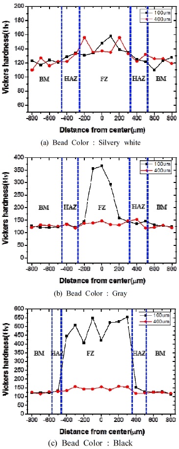
경도시험기를 이용하여 용접부의 경도측정을 실시한 결과를 Figure 10에 나타낸다. 경도 측정은 하중 100 g, 유지시간 10초의 조건에서 비드표면 100㎛, 400㎛아래에서부터 100㎛간격으로 측정되었다. 시험 결과 모재의 경도값은 110~120 Hv로 나타났으며 용접부의 경도값은 보다 높은 값을 나타내었다. 은백색의 비드일때 용접부의 경도가 120~160 Hv로 모재대비 다소 증가하였으나, 비드색이 회색 및 노란색일 경우 각각 300~350 Hv, 400~500 Hv로 모재대비 경도값이 매우 증가하였다. 이것은 산화 및 질화로 인해 용접부내 산소와 질소의 함량이 증가하였기 때문으로 사료된다. 이러한 경향은 T. W. Na et al.의 연구[16]에서도 유사하게 나타난다.
비드색이 은백색일 경우에는 적절한 용접부 실드로 인해 취화되지 않은 건전한 용접부로 판단 할 수 있다. 반면 비드색이 회색 및 검은색일 경우 대기 중의 산소 및 질소의 반응으로 인해 경도값이 모재대비 3배이상 크게 상승하므로 용접부가 취화되었음을 알 수 있었다.
4. 결 론
순 타이타늄에 대하여 적절한 실드가스의 종류 및 유량을 도출하기 위한 레이저 용접을 실시한 결과를 다음에 정리한다.
- (1) 실드가스 종류를 변화하여 실험한 결과, 전면실드에 일반 아르곤 및 고순도 헬륨을 사용한 경우 은백색의 건전한 비드가 나타났다.
- (2) 전면실드에 아르곤을 사용하고 실드가스 유량을 변화하여 실험한 결과, 유량이 15ℓ/min이하일 때 험핑비드가 발생하고 표면비드가 불균일하였으나 유량 20ℓ/min 이상에서는 대기로부터 용접부를 적절히 보호하여 은백색의 양호한 비드를 얻을 수 있었다.
- (3) 광학현미경 및 주사전자현미경을 이용하여 용접부의 미세조직을 관찰한 결과, 은백색 비드의 용접부에서 조대한 조직이 나타났으며 회색 및 검은색 비드의 용접부에서는 비드 상부에서 덴드라이트 형상의 조직이 관찰되었으며 검은색 비드에서 이러한 조직이 더 두드러지게 나타났다.
- (4) 각 비드색에 대한 비드 표면의 EDS점 분석을 한 결과, 대기 분위기 중 용접을 실시한 회색 비드의 표면에서 산소량이 가장 높게 나타났으며 이것은 순 타이타늄이 질소보다 산소와의 반응성이 더 높기 때문으로 판단된다.
- (5) 각 비드색에 따른 경도특성을 평가한 결과, 은백색 비드는 120~160Hv로 취화되지 않은 건전한 용접부였으나 회색과 검은색 비드는 모재보다 3배이상 경도가 증가하였다.
References
- C. Veiga, J. P. Davim, A. J. R. Loureiro, “Properties and applications of titanium alloys: A brief review”, Advanced Materials Science, 32(2), p133-148, (2012).
-
V. A. R. Henriques, “Titanium production for aerospace applications”, Journal of Aerospace Technology and Management, 1(1), (2009).
[https://doi.org/10.5028/jatm.2009.01010717]

- M. Peters, J. Kumpfert, C. H. Ward, and C. Leyens, “Titanium alloys for aerospace applications”, Advanced Engineering Materials, 5(6), p419-427, (2003).
-
A. Mannucci, L. Tomashchuk, A. Mathieu, E. Cicala, T. Boucheron, R. Bolot, and S. Lafaye, “Direct laser welding of pure titanium to austenitic stainless steel”, Procedia CIRP, 74, p485-490, (2018).
[https://doi.org/10.1016/j.procir.2018.08.138]

-
R. Palanivel, I. Dinaharan, and R. F. Laubscher, “Microstructure evolution and mechanical characterization of Nd:YAG laser beam welded titanium tubes”, Materials Characterization, 134, p225-235, (2017).
[https://doi.org/10.1016/j.matchar.2017.10.025]

-
J. Shi, G. Song, and J. Chi, “Effect of active gas on weld appearance and performance in laser-TIG hybrid welded titanium alloy”, International Journal of Lightweight Materials and Manufacture, 1(1), p47-53, (2018).
[https://doi.org/10.1016/j.ijlmm.2018.03.002]

-
S. M. Carvalho, C. A. R. P. Baptista, and M. S. F. Lima, “Fatigue in laser welded titanium tubes intended for use in aircraft pneumatic systems”, International Journal of Fatigue, 90, p47-56, (2016).
[https://doi.org/10.1016/j.ijfatigue.2016.04.018]

-
Pei-quan XU, “Microstructure characterization of Ti– 6Al–4V titanium laser weld and its deformation”, Transactions of Nonferrous Metals Society of China, 22(9), p2218-2123, (2012).
[https://doi.org/10.1016/s1003-6326(11)61437-4]

-
H. Liu, J. Shui, T. Cai, and Q. Chen, “Microstructural evolution and hardness response in the laser beam welded joints of pure titanium during recrystallization and grain growth”, Materials Characterization, 145, p87-95, (2018).
[https://doi.org/10.1016/j.matchar.2018.08.036]

-
Y. Zhang, Y. Ying, X. Liu, and H. Wei, “Deformation control during the laser welding of a Ti6Al4V thin plate using a synchronous gas cooling method”, Materials and Design, 90, p931-941, (2016).
[https://doi.org/10.1016/j.matdes.2015.11.035]

-
R. Li, Z. Li, Y. Zhu, and L. Rong, “A comparative study of laser beam welding and laser-MIG hybrid welding of Ti-Al-Zr-Fe titanium alloy”, Materials Science and Engineering A, 528(3), p1138-1142, (2011).
[https://doi.org/10.1016/j.msea.2010.09.084]

- J. D. Kim, and Y. S. Kim, Easy to Understand Welding Engineering, Korea, Dasom, (2010), (in Korean).
-
S. J. Lee, K. D. Choi, B. H. Park, J. D. Kim, and J. Suh, “Weldability of aluminium alloys laser welding for with high-power disk laser”, Journal of the Korean Society of Marine Engineering, 41(7), p638-645, (2017), (in Korean).
[https://doi.org/10.5916/jkosme.2017.41.7.638]

-
T. Jwad, S. Deng, H. Butt, and S. Dimov, “Laser induced single spot oxidation of titanium”, 387(30), p617-624, (2016).
[https://doi.org/10.1016/j.apsusc.2016.06.136]

- J. Liu, Y. Li, S. Arumuga, J. Tudor, and S. Beedy, “Investigation of low temperature processed titanium dioxide(TiO2) film for printed dye sensitized solar cells(DSSCs) for large area flexible applications”, Materials Today: Proceedings, 5(5), p13846-13854, (2018).
-
T. W. Na, W. R. Kim, S. M. Yang, O. Kwon, J. M. Park, G. H. Kim, K. H. Jung, C. W. Lee, H. K. Park, and H. G. Kim, “Effect of laser power on oxygen and nitrogen concentration of commercially pure titanium manufactured by selective laser melting”, Materials Characterization, 143, p110-117, (2018).
[https://doi.org/10.1016/j.matchar.2018.03.003]


