Flow analysis of the baffle structure of a scrubber for small marine engines
Copyright ⓒ The Korean Society of Marine Engineering
This is an Open Access article distributed under the terms of the Creative Commons Attribution Non-Commercial License (http://creativecommons.org/licenses/by-nc/3.0), which permits unrestricted non-commercial use, distribution, and reproduction in any medium, provided the original work is properly cited.
Abstract
A scrubber is a typical piece of equipment used to reduce the amount of sulfur oxides emitted from marine engines. Many different types of scrubbers have been studied. In this research, the influence of two different types of scrubber structures on backpressure and flow streamlines was studied. Backpressure is closely related to the power and efficiency of the engine, and the behavior of the flow streamlines is related to the duration for which the exhaust gas and cleaning water are in contact. The length and number of horizontal and vertical baffles were calculated and analyzed. The result showed that an inner structure with a baffle length ratio of 0.6 with two baffles was considered optimal in the case of a horizontal scrubber, whereas a baffle length ratio of 0.7 with two baffles was considered optimal in the case of a vertical scrubber.
Keywords:
Backpressure, Streamline, Baffle, Optimal structure, Scrubber1.Introduction
Many types of equipment and systems are installed in an exhaust pipeline to reduce emissions and to increase thermal efficiency, such as a turbocharger, economizer, selective catalytic reduction system (SCR), heat recovery system, catalytic converter, and scrubber.
A turbocharger is a type of turbine-driven forced induction installation used to increase the power and efficiency of an internal combustion engine by intaking more air into the combustion chamber [1]-[3]. SCR is a method for converting NOx into N2 and H2O in the presence of a catalyst. It is widely used in diesel engines to reduce NOx. Kuroki et al. studied a type of commercial-scale indirect plasma and chemical hybrid system that was 15 times more economical than the conventional SCR system [4]. An exhaust heat recovery system is a technology that translates thermal losses in the exhaust pipeline into energy to save fuel and reduce CO2 emissions. Kyriakidis et al. optimized a model of a waste heat recovery system for a two-stroke marine diesel engine [5]. Economizers are mechanical installations intended to reduce energy consumption or to preheat a fluid [6]. A catalytic converter is a type of exhaust emission control device, and it is designed to convert toxic gases and pollutants into less toxic pollutants from the exhaust gas of an internal combustion engine by catalyzing a redox reaction [7].
A scrubber is an important installation in an internal combustion engine for reducing SOx emissions. Many studies on scrubbers have been conducted [8]-[11]. Bal et al. studied the fluid flow behavior and the effect of different parameters on backpressure in a Venturi scrubber [8]. This type of scrubbes is installed in an exhaust pipeline, which causes an increase in the backpressure and thus affects engine performance. However, the effect of the structure variation on the backpressure of small marine engines has not been studied sufficiently.
This research is concerned with the influence of two different types of scrubber structures on backpressure and streamlines. Backpressure is closely related to the power and efficiency of the engine, and the behavior of the flow streamlines is related to the duration for which the exhaust gas and cleaning water are in contact [12]-[15]. The length and number of baffles of the horizontal and vertical types are calculated and analyzed.
2.Mathematical model and calculation conditions
2.1 Mathematical model
The continuous equation is given as
| (1) |
Momentum equations are given as
| (2) |
| (3) |
Energy equations are given as
| (4) |
| (5) |
where U is the velocity vector, γ is the stress, SM is a source of momentum, T is the temperature, δ is a unit matrix, ρ is the density, p is the pressure, h is the enthalpy, λ is the heat conduction ratio, v is the volume, u is the internal energy, and SE is the generated energy.
A shear stress transport (SST) model is used to calculate turbulent flow.
The turbulent viscosity is calculated by the equation
| (6) |
The blending functions are given as
| (7) |
| (8) |
where k is the turbulence kinetic energy, ω is the specific dissipation rate, ρ is the density, S is the strain rate magnitude, and a* is the compensation factor.
2.2 Calculation structure
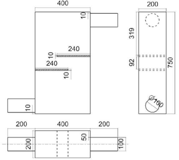
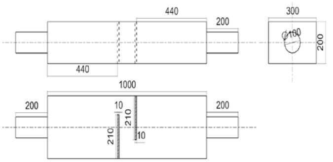
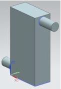
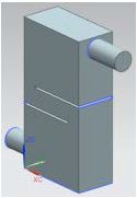
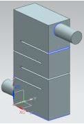
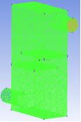
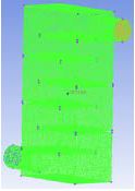
Two types of scrubbers were used in the calculation. Both volumes were 60 L. The two-dimensional and three-dimensional patterns were set up using NX 9.0. The two-dimensional patterns are shown in Figure 1 and Figure 2.
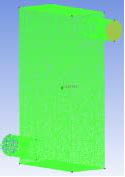
The scrubbers were divided into two groups. Group 1 was equipped with horizontal baffles, and Group 2 was equipped with vertical baffles. The graphic models and mesh models are shown in Table 1 and Table 2.
The mesh files were set up by ICEM CFD. The mesh elements and nodes were generated as the same number to reduce the mesh effect on the calculation. A volume mesh was adopted, and the mesh type was tetra/mixed. The element size of the mesh was 0.009. This kept the mesh number to more than 2 million and maintained good performance. In Group 1, the empty scrubber had 1,223,134 mesh elements and 206,705 nodes. The scrubber with two baffles had 1,223,134 elements and 206,705 nodes. The scrubber with four baffles had 1,200,424 elements and 203,907 nodes. The scrubber with six baffles had 1,200,424 elements and 203,907 nodes. In Group 2, the number of mesh elements was 1,200,424, and the number of nodes was 203,907 for all the cases. ANSYS was used for the simulation and calculations after grid division. The residual targets were set up in 10-6 according to experience.
2.3 Calculation conditions
The flow rates for the test engine are shown in Table 3. The simulation variables are the length and number of baffles, which are shown in Table 4.
l1 is the length of the baffle in Group 1, and l2 is the length of the baffle in Group 2. In the vertical scrubber, the ratio equals the baffle length divided by the scrubber length. In the horizontal scrubber, the ratio equals the baffle length divided by the scrubber height.
3.Calculation results and discussion
3.1 Horizontal baffle structure
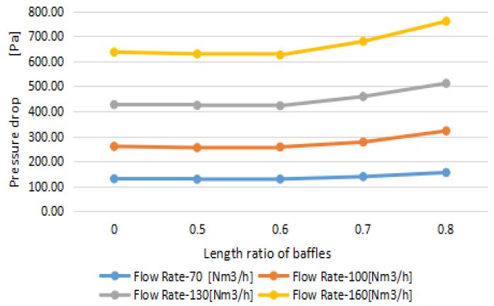
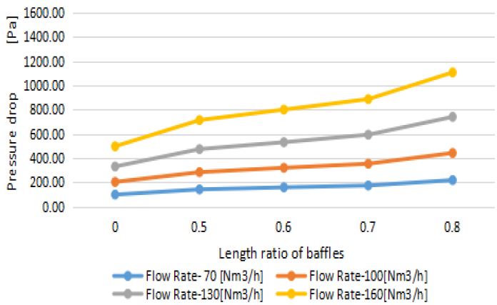
The pressure drop of the structure having two horizontal baffles is shown in Figure 3, where the “0” indicates no baffle.
Figure 3 shows the variation in pressure drop with the length ratio of the baffles. The pressure drop increased with an increase in the length ratio. At a low flow rate of 70 Nm3/h, the increase in the pressure drop was not very remarkable as the length ratio increased. When the flow rate increased, the pressure drop also increased with the length ratio. At all the flow rates from 70 to 160 Nm3/h, the pressure drop remained until a length ratio of 0.6 and increased significantly over a length ratio of 0.7. The result showed that the length ratio of the baffle should be less than 0.6.
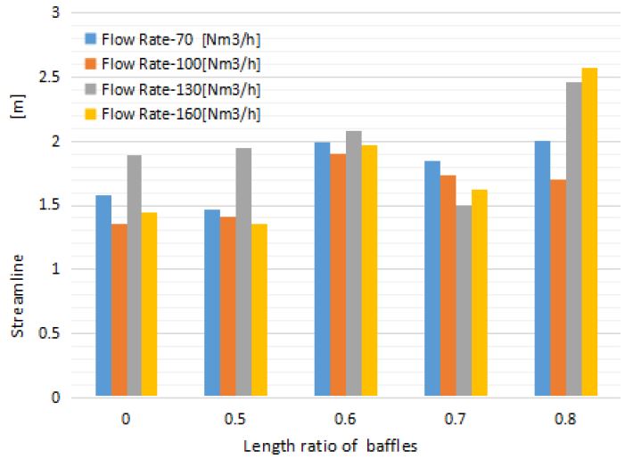
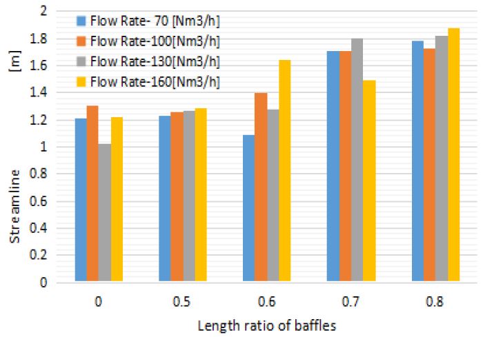
Figure 4 shows the average length of the streamlines with different lengths of horizontal baffles. The average length of the streamline is the average flow distance. It is not very dependent on the flow rate. The length of the streamline increased with an increase in baffle length ratio until 0.6, decreased at a ratio of 0.7, and increased again at 0.8. The result shows that a baffle length ratio of 0.8 is the best, and a baffle length ratio of 0.6 is the next best. In conjunction with the result shown by Figure 3, the results showed that the length ratio of the baffles should be 0.6.
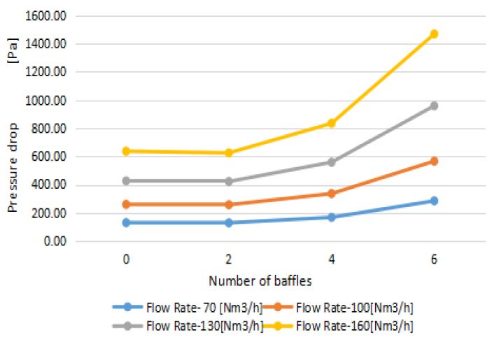
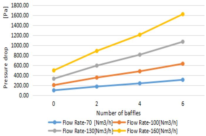
The calculation result showed that a structure with a baffle length ratio of 0.6 is optimal. A baffle length ratio of 0.6 was selected when analyzing baffles with different numbers. The variable was the number of baffles. The simulation was divided into four groups. The number of baffles in each group was 0, 2, 4, and 6. The result of the pressure drop is shown in Figure 5.
Figure 5 shows the variation in pressure drop with different numbers of baffles. The pressure drop increased as the number of baffles increased. At a low flow rate of 70 Nm3/h, the increase in the pressure drop was not very remarkable as the number of baffles increased. When the flow rate increased, the pressure drop rate also increased with the number of baffles. At all the flow rates, from 70 to 160 Nm3/h, the pressure drop remained a slow increasing trend until four baffles and increased substantially at more than six baffles. The result showed that the number of baffles should be less than four.
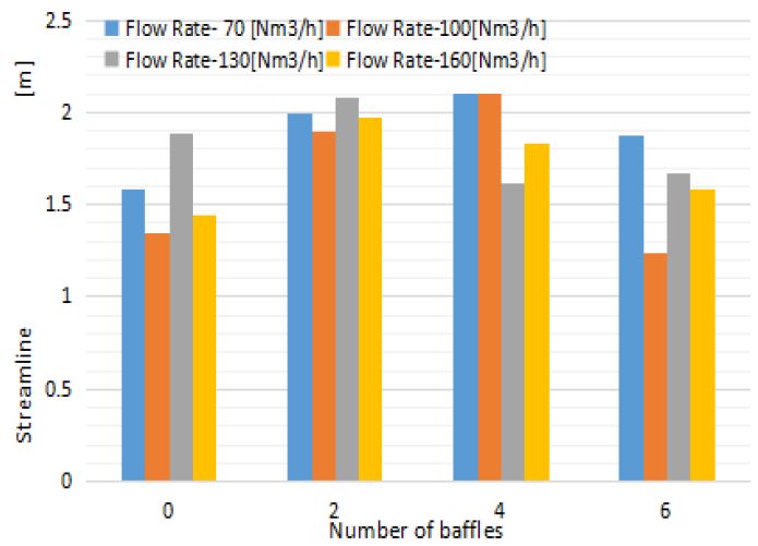
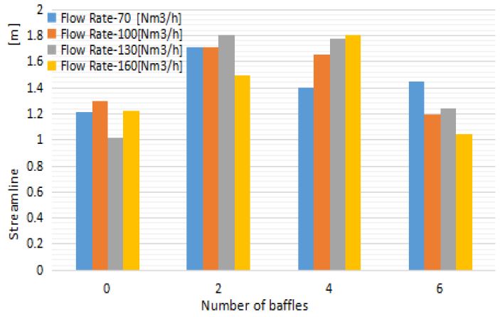
Figure 6 shows the average length of streamlines with different numbers of horizontal baffles. The average length of the streamline is the average flow distance. It is not very dependent on the flow rate. The length of the streamline increased as the number of baffles increased until four and decreased when the number of baffles was six. The result showed that a structure with two baffles is the best, and that with four baffles is the second best. In conjunction with the result shown in Figure 5, the number of baffles should be two or four.
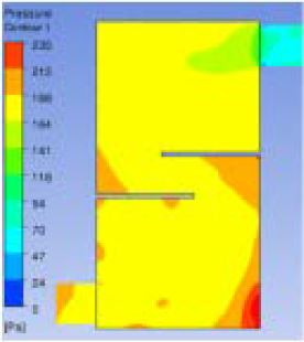
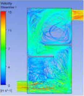
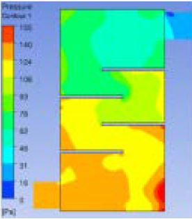
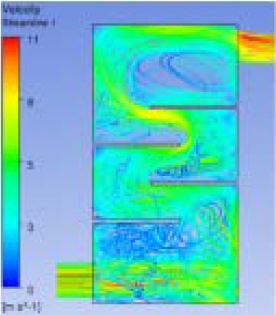
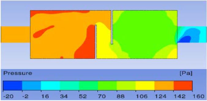
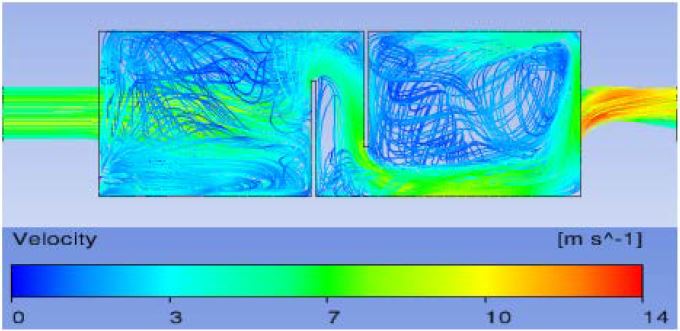
The pressure drop and streamline of a scrubber with two and four horizontal baffles at a flow rate of 70 Nm3/h and a baffle length ratio of 0.6 are shown in Figure 7, Figure 8, Figure 9, and Figure 10.
Figure 7 shows that the inlet pressure was approximately 190 Pa, and the outlet pressure was approximately 70 Pa. The pressure decreased from the inlet to the outlet. The pressure of the lower right corner was approximately 235 Pa, which was the highest. Figure 8 shows that the velocity of gas increased from the inlet to the outlet. The inlet velocity was approximately 7 m/s, and the outlet velocity was approximately 11 m/s. Figure 9 shows that the inlet pressure was approximately 140 Pa, and the outlet pressure was approximately 30 Pa. Pressure decreased from the inlet to the outlet. The pressure of the lower right corner was approximately 155 Pa, which was the highest. Figure 10 shows that the velocity of gas increased from the inlet to the outlet. The inlet velocity was approximately 7 m/s, and the outlet velocity was approximately 8 m/s.
3.2 Research in the case of vertical baffles
The research method was the same with a scrubber of horizontal baffles. The simulation variable was the baffle length, which was divided into five groups. The result is shown in Figure 11.
Figure 11 shows the variation in pressure drop with the length ratio of the baffles. The pressure drop increased with length ratio increase. At a low flow rate of 70 Nm3/h, the pressure drop was not very remarkable as the length ratio increased. When the flow rate increased, the pressure drop rate also increased with the length rate. At all the flow rates, from 70 to 160 Nm3/h, the pressure drop remained a slow increasing trend until the length ratio of 0.7 and increased substantially over a length ratio of 0.8. The result showed that the length ratio of the baffle should be less than 0.7.
Figure 12 shows the average length of the streamlines with different lengths of vertical baffles. The average length of the streamline was the average flow distance. It was not particularly dependent on the flow rate. The length of the streamline increased with an increase in the baffle length ratio from 0 to 0.8. The result showed that a baffle length ratio of 0.8 is the best, and a baffle length ratio of 0.7 is the next best. In conjunction with the result shown in Figure 11, the length ratio of the baffles should be 0.7.
The former calculation result shows that a baffle length ratio of 0.7 is the optimal structure. A baffle length ratio of 0.7 should be selected when analyzing baffles with different numbers. The variable is the number of baffles. The simulation was divided into four groups. The number of baffles in each group was 0, 2, 4, and 6. The result of the pressure drop is shown in Figure 13.
Figure 13 shows the variation in pressure drop with different numbers of baffles. The pressure drop increased with an increase in the number of baffles. At a low flow rate of 70 Nm3/h, the pressure drop was not very remarkable as the number of baffles increased. When the flow rate increased, the pressure drop rate also increased with the baffle number rate. At all the flow rates, from 70 to 160 Nm3/h, the pressure drop remained a similar increasing trend. The result showed that the higher the number of baffles employed, the larger is the pressure drop.
Figure 14 shows the average length of streamlines with different numbers of horizontal baffles. The average length of the streamline is the average flow distance. It is not very dependent on the flow rate. The length of the streamline increased with an increase in the number of baffles until four, then decreased at six. The result shows that two baffles are best, and four baffles are second best. In conjunction with the result shown in Figure 13, the number of baffles should be two.
At a flow rate of 70 Nm3/h, the pressure drop and streamline of the scrubber with two vertical baffles in a length ratio of 0.7 are shown in Figure 15 and Figure 16.
Figure 15 shows that the inlet pressure was approximately 140 Pa, and the outlet pressure was approximately 10 Pa. The Pressure decreased from the inlet to the outlet. The pressure was very high at the corner of the first baffle. Figure 16 shows that the velocity of the gas increased from the inlet to the outlet. The inlet velocity was approximately 7 m/s, and the outlet velocity was approximately 10 m/s.
4.Conclusion
This research investigated the influence of baffle lengths and numbers for two types of scrubber for small marine engines.
In the case of horizontal baffles:
- The pressure drop remained low until a length ratio of 0.6, and the average length of the streamline was the best at a baffle length ratio of 0.8.
- The pressure drop slowly increased until four baffles, and the average length of the streamlines was longest with two baffles.
- The optimal inner structure was a baffle length ratio of 0.6 with two baffles in the case of horizontal baffles.
In the case of vertical baffles:
- The pressure drop slowly increased until a length ratio of 0.7, and the streamline length increased with an increase in baffle length.
- The higher the number of baffles, the larger was the pressure drop, and the average length of the streamlines was longest with two baffles.
- The optimal inner structure was a baffle length ratio of 0.7 with two baffles in the case of vertical baffles.
References
-
O. Chiavola, F. Palmieri, and E. Recco, “Turbocharger speed estimation via vibration measurements for combustion sensing”, Energy Procedia, 126, p842-849, (2017).
[https://doi.org/10.1016/j.egypro.2017.08.281]

- A. Romagnoli, A. Manivannan, S. Rajoo, M. S. Chiong, A. Feneley, A. Pesiridis, and R. F. Martinez-Botas, “A review of heat transfer in turbochargers”, Renewable and Sustainable Energy Reviews, 79, p1442-1460, (2017).
- A. Grönman, P. Sallinen, J. Honkatukia, J. Backman, and A. Uusitalo, “Design and experiments of two-stage intercooled electrically assisted turbocharger”, 111, p115-124, (2016).
-
T. Kuroki, H. Fujishima, K. Otsuka, T. Ito, M. Okubo, T. Yamamoto, and K. Yoshida, “Continuous operation of commercial-scale plasma-chemical aftertreatment system of smoke tube boiler emission with oxidation reduction potential and pH control”, Thin Solid Film, 516(19), p6704-6709, (2008).
[https://doi.org/10.1016/j.tsf.2007.11.101]

-
F. Kyriakidis, S. Kim, S. Singh, and C. Thomas, “Modeling and optimization of integrated exhaust gas recirculation and multi-stage waste heat recovery in marine engines”, Energy Conversion and Management, 151, p286-295, (2017).
[https://doi.org/10.1016/j.enconman.2017.09.004]

-
Q. Ding, X. F. Tang, and Z. G Yang, “Failure analysis on abnormal corrosion of economizer tubes in a waste heat boiler”, Engineering Failure Analysis, 73, p129-138, (2017).
[https://doi.org/10.1016/j.engfailanal.2016.12.011]

-
I. Cornejo, P. Nikrityuk, and Robert E. Hayes, “Multiscale RANS-based modeling of the turbulence decay inside of an automotive catalytic converter”, Chemical Engineering Science, 175, p377-386, (2018).
[https://doi.org/10.1016/j.ces.2017.10.004]

-
M. Bal, and B. C. Meikap, “Prediction of hydrodynamic characteristics of a venturi scrubber by using CFD simulation”, South African Journal of Chemical Engineering, 24, p222-231, (2017).
[https://doi.org/10.1016/j.sajce.2017.10.006]

-
R. W. K. Allen, and A. van Santen, “Designing for pressure drop in Venturi scrubbers: the importance of dry pressure drop”, The Chemical Engineering Journal and the Biochemical Engineering Journal, 61(3), p203-211, (1996).
[https://doi.org/10.1016/0923-0467(95)03044-1]

-
Z. Luan, X. Liu, M. Zheng, and L. Zhu, “Numerical Simulation of Square Section Venturi Scrubber with Horizontal Spray”, Procedia Computer Science, 107, p117-121, (2017).
[https://doi.org/10.1016/j.procs.2017.03.066]

-
P. Goel, A. Moharana, and Arun K. Nayak, “Measurement of scrubbing behavior of simulated radionuclide in a submerged venturi scrubber”, Nuclear Engineering and Design, 327, p92-99, (2018).
[https://doi.org/10.1016/j.nucengdes.2017.12.003]

-
X. M. Zhang, H. Y. Li, L. Zheng, Z. G. Chen, and C. K. Qin, “Combustion characteristics of porous media burners under various back pressures: An experimental study”, Natural Gas Industry B, 4(4), p264-269, (2017).
[https://doi.org/10.1016/j.ngib.2017.08.009]

-
H. Sapra, M. Godjevac, K. Visser, D. Stapersma, and C. Dijkstra, “Experimental and simulation-based investigations of marine diesel engine performance against static back pressure”, Applied Energy, 204, p78-92, (2017).
[https://doi.org/10.1016/j.apenergy.2017.06.111]

-
S. M. Lee, and K. H. Park, “Study of inner structure of in-line scrubbers”, Journal of the Korean Society of Marine Engineering, 42(1), p1-9, (2018), (in Korean).
[https://doi.org/10.5916/jkosme.2018.42.1.1]

-
K. Son, J. Y. Lee, and K. H. Park, “The effect of spray flow rate, aspect ratio, and filling rate of wet scrubber on smoke reduction”, Journal of the Korean Society of Marine Engineering, 39(3), p217-222, (2015), (in Korean).
[https://doi.org/10.5916/jkosme.2015.39.3.217]


