Numerical analysis of the effect of baffle orientation and baffle size on shell-side pressure drop in a liquefied natural gas (LNG) vaporizer
Copyright ⓒ The Korean Society of Marine Engineering
Abstract
In this numerical study, the effect of baffle orientation and baffle size on the shell-side pressure drop in a liquefied natural gas (LNG) vaporizer was investigated. The shell side of the LNG vaporizer with vertical, horizontal and rotated baffle orientations and baffle cuts of 30%, 40% and 50% has been solved by ANSYS CFX 16.2. The results showed that the horizontal baffle orientation demonstrated a lower pressure drop compared to the vertical and rotated baffle orientations, and the 50% baffle cut had a lower pressure drop compared to that in the other two baffle cuts in all baffle orientations. The results also showed that the dependency of the pressure drop on the Reynolds number appeared to decrease for all baffle orientations when baffle cuts increased from 30% to 50%.
Keywords:
LNG Vaporizer, Baffle, Pressure drop, CFD1.Introduction
A heat exchanger is a device used for transferring heat from one medium to another [1]. Various types and configurations of heat exchangers are used in many industrial applications such as power generation, energy storage, air-conditioning system, and materials processing. More than 30% of the industrial heat exchangers in use are shell and tube heat exchangers [2][3] and the same model is employed in this study. The flow in the shell side of the shell and tube heat exchanger with segmental baffles is complex. To verify the performance of the heat exchanger, pressure drop and heat transfer are considered as the important parameters.
Many researchers have described the methods of calculating the pressure drop in the shell side of a heat exchanger. The D. Q. Kern [4] and K. J. Bell [5] methods based on correlation approaches are typically used for calculating the pressure drop in the shell side of the heat exchanger. The Kern method is used for preliminary design and yields traditional results, whereas the Bell-Delaware method yields more detailed results for typical shell-side geometry arrangements. H. Halle et al. [6], T. Pekdemir et al. [7], U. C. Kapale et al. [8], and E. S. Gaddis et al. [9], investigated the pressure drop of the shell and tube heat exchanger and developed a shell- side pressure drop model. B. A. Abdelkader et al. [10] showed the effects of baffle cut sizes on the pressure drop in a shell and tube heat exchanger. They found that, the pressure drop decreases with an increase in the baffle cut. They analyzed a large number of baffles and observed that the pressure drop decreases with an increase in the baffle cut at a higher rate than for a small number of baffles. M. Mellal et al. [11] observed that the baffle orientation is an important parameter to design an efficient shell and tube heat exchanger. They performed their study on the shell side of a heat exchanger under different baffle arrangement and orientations. E. Ozden et al. [12] analyzed the shell side of the heat exchanger using CFD techniques. They performed observations by varying the baffle cut values of 36% and 25%, the results showed that the 25% baffle cut yields slightly better results compared to the 36% baffle cut. A. S. Ambekar et al. [13] studied shell and tube heat exchangers with different baffle configurations. H. Afrianto et al. [14] studied the effect of mass flow rate and heat transfer characteristics in a 1-2 pass shell and tube heat exchanger with segmental baffles using CFD. S. M. Sayeed bin asad et al. [15] experimentally studied the shell side flow characteristics in an LNG vaporizer with two different baffles cut: 15% and 30% of the shell’s inner diameter. They found some vortex shaped flow throughout the whole shell for a 15% baffle cut, which is rare in 30% baffle cut. G. H. Doo et al. [16][17] analyzed the behavior of units fitted with baffle having horizontal and vertical cuts. These works suggested a gravitational flow through the heat exchanger shells. K. Mohammadi et al. [18] investigated the effect of baffle orientation on the heat transfer and pressure drop in the shell and tube heat exchanger with leakage flows. They observed that the orientation of baffles has a considerable influence on the shell side pressure drop.
In summary, although there is considerable research on heat exchanger, the available data in the industry is still insufficient. In this study, three different baffle sizes and three different baffle orientations were considered for calculating the shell-side pressure drop. The present study aims to compare the effects of various baffles shapes such as horizontal, vertical and rotated baffle orientation and the baffle cut sizes on the shell-side pressure drop. Herein, only the shell-side pressure drop of the heat exchanger was focused on, the effect of baffle cut and baffle orientation on heat transfer and pressure drop is reported.
2.Numerical Analysis
2.1 Description of Problem
A U type counter flow shell and tube heat exchanger consists of two sides, the shell side and tube side. The shell-side and tube-side fluids are separated by a tube sheet. It is simple to adjust the tube-side parameters but difficult to obtain the appropriate combination of parameters for the shell side. The shell side of the heat exchanger has a container for the shell fluid, which consists of baffles and tie rods. Baffles, the primary component in the shell side, are used to support the tubes, preventing tube vibration and sagging, maintain the tube spacing, and divert the flow across the bundle. For a given shell geometry, the configuration depends on the baffle cut, baffle spacing and baffle orientation. However, after installing the baffles, the shell-side flow introduces an intricate flow structure owing to the presence of baffles. For minimizing the intricate flow structure and increasing the performance of the shell and tube heat exchanger, the shell-side baffle can be designed in various configurations such as the curve baffle, helical baffle and segmental baffle.
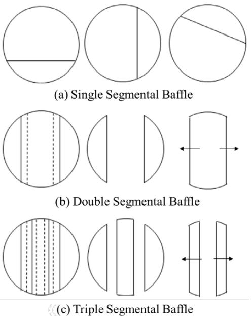
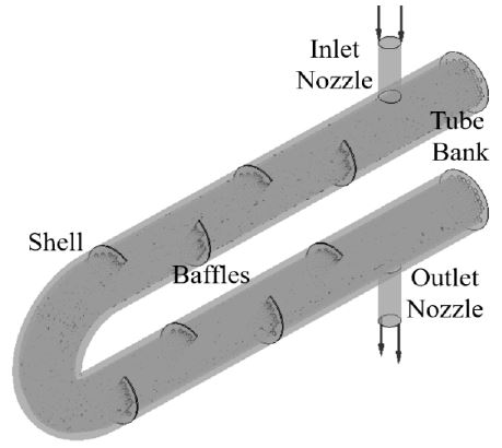
A segment, called the baffle cut, is cut to allow the fluid to flow parallel to the tube axis, as it flows from one baffle space to another. Figure 1 shows the types of baffle segments. The most typically used baffle type is the single segmental baffle, which is also used in the present study owing to its easy construction when compared to the curve or helical baffles. The baffle cut should be carefully set because a baffle cut that is either too large or too small can increase the possibility of fouling in the shell and would also lead to pressure drop. Regarding baffle spacing, the shell and baffle geometry arrangement should be changed to achieve the desired output. Owing to the baffles, the shell and tube heat exchanger may be divided into three different zones, inlet, intermediate, and outlet. The inlet zone is the sector between the inlet nozzle and the first baffle. The outlet zone is the sector between the outlet nozzle and the last baffle, and the intermediate zone is the sector between the first and the last baffle. The number of baffles can be calculated by conventional method. However, this formula assumes that the inlet zone and outlet zone baffle spacing are the same as the central baffle spacing. To minimize the pressure drop at the inlet and outlet zones, the inlet baffle spacing and the outlet baffle spacing must be larger than the axial baffle spacing. In this study, eight baffles were placed along the shell in alternating orientations with the cut facing up, cut facing down, cut facing up again, etc., to create the flow paths across the tube bundle. For each baffle cut, the baffle orientation with the same baffle spacing in different mass flow rates at inlet were investigated. These mass flow rates were introduced in terms of the inlet Reynolds number which is defined based on the velocity at the inlet nozzle, the internal diameter of the inlet nozzle, and the physical properties of the shell-side inlet fluid.
2.2 Geometry Modeling
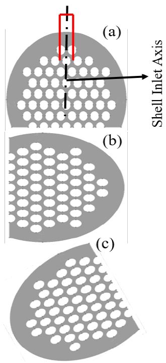
The three-dimensional model of the shell-side geometry of the shell inlet nozzle, shell outlet nozzle, tube bank and shell baffles is shown in Figure 2. The model geometry is created using CATIA V5R18 and meshing is performed using ICEM CFD via the fine mesh method. The baffles cut are 30%, 40%, and 50% of the shell inner diameter, and the baffles orientations are horizontal, vertical, and rotated, as shown in Figure 3. Table 1 lists the dimensions of the shell-side LNG vaporizer specifications.
2.3 Governing Equations
The governing equations used to solve the continuity and momentum conservation are specified by Equation (1) and Equation (2) - Equation (4) respectively. The k–omega turbulence model presented in Equation (5) and Equation (6) based on the shear stress transport (SST) model is used to handle the turbulence developed along the shell domain.
Continuity equation:
| (1) |
Momentum equations:
X-momentum equation:
| (2) |
Y-momentum equation:
| (3) |
Z-momentum equation:
| (4) |
SST k-omega Model:
Turbulence Kinetic Energy:
| (5) |
Specific Dissipation Rate:
| (6) |
2.4 Boundary Conditions
Different boundary conditions were adopted for different boundary zones. The mass flow rate was assigned as the boundary condition for the inlet. Five distinct inlet boundary conditions were used for the five different mass flow rates. The mass flow rates used in this study are 10000, 12500, 15000, 17500, and 20000 kg/hr. The pressure was assigned as the boundary condition for the outlet, and its value was 0 Pa at the outlet condition, to simplify the numerical computations. The working fluid was water with density 997.0 kg/m3. The simulation parameters of the baffles in the LNG vaporizer are listed in Table 2.
3.Results and Discussion
3.1 Validation of Numerical Model
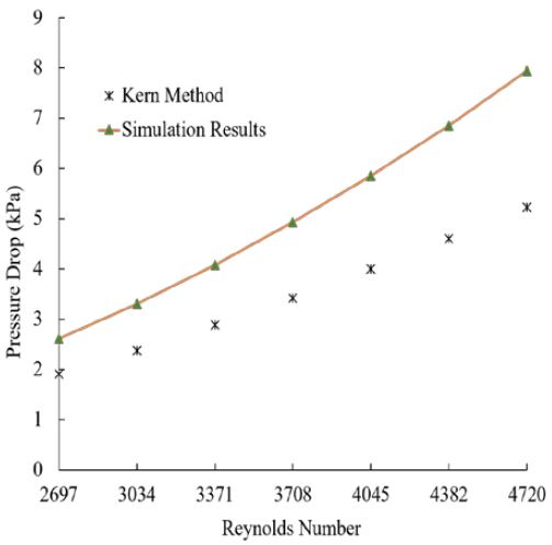
To validate the numerical model, the Kern method was used to calculate the overall pressure drop in the shell side of shell and tube heat exchanger.
Pressure drop in the shell side:
| (7) |
Where, f is the friction factor, ρ is the density of the fluid, Ds is the shell inner diameter, u is the velocity of the fluid, L is the length of the shell, Ls is the baffle spacing, de is the shell equivalent diameter.
The equation of the shell equivalent diameter is:
| (8) |
Where pt is the tube pitch and do is the external tube diameter. The pressure drop values were calculated from difference between the pressures at the entrance and exit nozzles on the shell side in the simulation results. Figure 4 shows the comparison of the simulation results using the Kern method. We found that the pressure drop results from the simulation and the Kern method which depends on the Reynolds number variation, agree well. A comparison of the results for the shell-side pressure drop from the Kern method as well as from the simulation program is shown in Figure 4. The difference in the results obtained using the simulation study and the Kern method varied between 0.7~2.71 kPa.
3.2 Velocity and Streamline Distribution
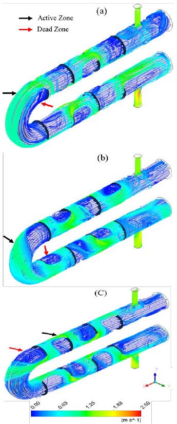
The velocity distributions and streamlines of the shell and tube heat exchanger are shown in Figure 5, for the same Reynolds number 4720. Figure 5 (a), Figure 5 (b), and Figure 5 (c) show the horizontal, vertical, and rotated baffle orientations, respectively. The baffle cut was 30% of the shell inner diameter. In the shell side flow, two zones, namely, the active and dead zones are indicated by black and red arrow signs, respectively. These zones exist between the two baffles. The active zone has a high velocity whereas the dead zone has almost zero velocity as indicated by the velocity legend view. As shown in Figures 5 (a) and Figure 5 (b), for the horizontal baffle orientation case, the streamline flow is vertical (up and down) between the baffles, whereas for the vertical baffle orientation case, the streamline flow is horizontal (side by side) at the inner shell wall. As shown in Figure 5 (c), for the rotated baffle orientation case, the streamline flow is twisted under compression when compared to the horizontal and vertical baffle orientations.
3.3 Baffle Orientation Effects on Pressure Drop
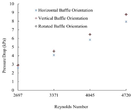
Figure 6 shows the graph of the shell-side pressure drop versus the Reynolds number of the shell-side fluid. The shell-side pressure drop is calculated for the horizontal, vertical, and rotated baffle orientations. The shell-side pressure drop for the vertical and rotated baffle orientation is greater when compared to the shell-side pressure drop for the horizontal baffle orientation.
3.4 Baffle Cut Effects on Pressure Drop
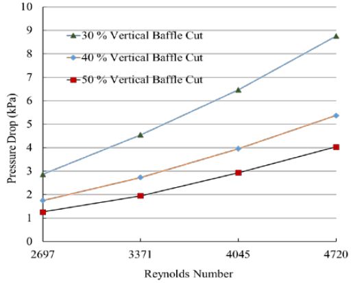
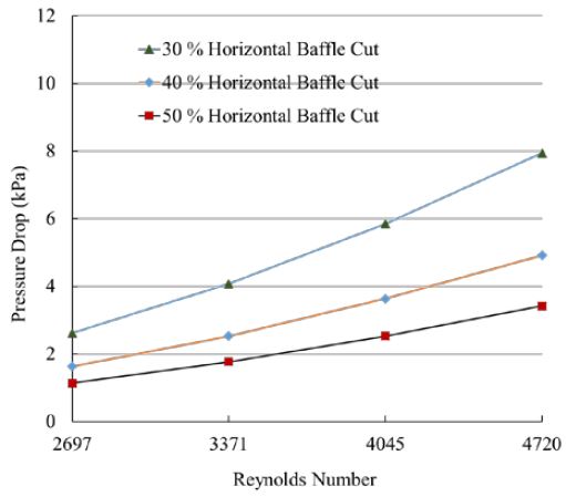
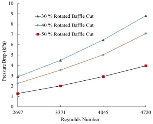
Figure 7 to Figure 9 show the shell-side pressure drop as a function of the baffle cut. The figures show that the pressure drop decreases with the increase in the baffle cut percentage. Figure 7 shows that the dependency of pressure drop on the baffle cut appears to decrease for the horizontal baffles orientation when the baffle cut increases from 30% to 50%. Similarly, from Figure 8 and Figure 9, the pressure drop is noted to decrease for the vertical and rotated baffle orientations whereas the baffles cut increases from 30% to 50%.
4.Conclusion
The shell side of a shell and tube type LNG vaporizer was modeled to investigate the pressure drop. From the CFD simulation, the velocity and streamlines were visualized and the following conclusions are derived:
- (a) Some recirculation regions appeared between the two baffles. In terms of the streamlines behavior, the horizontal baffle orientation was more stable compared to the vertical and rotated baffle orientations. In the rotated baffle orientation, the streamlines were more twisted under compression, compared to in the horizontal and vertical baffle orientations.
- (b) The pressure drop changed with change in the baffle orientation, and for the same Reynolds number, the pressure drops for the horizontal baffle orientation were always lower than those for the vertical and rotated baffle orientations.
- (C) The horizontal baffle orientation with a baffle cut of 50% represented the smallest pressure drop because more shell-side fluid could pass through the baffle window when the baffle cut was larger. However, the pressure drop increased when the baffle size decreased from 40% to 30%. Similar results were noted for the configuration with vertical and rotated baffle orientations.
Acknowledgements
This study was supported by the Ministry of Industry for Economic Cooperation (R0004786) and Human Resources Development Program in Energy Technology of the Korea Institute of Energy Technology Evaluation and Planning (KETEP) granted financial resource from the Ministry of Trade, Industry and Energy, Republic of Korea (No. 20184010201700).
References
- S. Kakac, and H. Liu, Heat Exchangers: Selection, Ratings and Thermal Design, 2nd edition, CRC Press, (2002).
-
B. I. Master, K. S. Chunanged, A. J. Boxma, D. Kral, and P. Stehlik, “Most frequently used heat exchangers from pioneering research to worldwide applications”, Heat Transfer Engineering, 27(12), p4-11, (2006).
[https://doi.org/10.1080/01457630600671960]

-
K. J. Bell, “Heat exchanger design for the process industries”, J. Heat Transfer, 126(6), p877-885, (2004).
[https://doi.org/10.1115/1.1833366]

- D. Q. Kern, Process Heat Transfer, McGraw-Hill, New York, (1950).
- K. J. Bell, Final Report of the Cooperative Research Program on Shell and Tube Heat Exchanger, University of Delaware, Engineering Experimental Station, Bulletin No. 5 (1963).
-
H. Halle, J. M. Chenoweth, and M. W. Wabsganas, “Shellside water flow pressure drop distribution measurements in an industrial-sized test heat exchanger”, Journal of Heat Transfer, 110, p60-67, (1988).
[https://doi.org/10.1115/1.3250474]

-
T. Pekdemir, T. W. Davies, L. E. Haseler, and A. D. Diaper, “Pressure drop measurements on the shell side of a cylindrical shell-and-tube heat exchanger”, Heat Transfer Engineering, 15(7), p42-56, (1994).
[https://doi.org/10.1080/01457639408939830]

-
U. C. Kapale, and S. Chand, “Modeling for shell-side pressure drop for liquid flow in shell and tube heat exchanger”, International Journal of Heat and Mass Transfer, 49(3-4), p601-610, (2006).
[https://doi.org/10.1016/j.ijheatmasstransfer.2005.08.022]

-
E. S. Gaddis, and V. Gnielinski, “Pressure drop on the shell side of shell and tube heat exchangers with segmental baffles”, Chemical Engineering and Processing, 36(2), p149-159, (1997).
[https://doi.org/10.1016/s0255-2701(96)04194-3]

- B. A. Abdelkader, and S. M. Zubair, “The Effect of a number of baffle on the performance of shell-and-tube heat exchanger”, Heat Transfer Engineering, 0, p1-14, (2017).
-
M. Mellal, R. Benzeguir, D. Sahel, and H. Ameur, “Hydro-thermal shell-side performance evaluation of a shell and tube heat exchanger under different baffle arrangement and orientation”, International Journal of Thermal Sciences, 121, p138-149, (2017).
[https://doi.org/10.1016/j.ijthermalsci.2017.07.011]

-
E. Ozden, and I. Tari, “Shell side CFD analysis of a small shell and tube heat exchanger”, Energy Conservation and management, 51(5), p1004-1014, (2010).
[https://doi.org/10.1016/j.enconman.2009.12.003]

-
A. S. Ambekar, R. Sivakumar, N. Anantharaman, and M. Vivekenendan, “CFD simulation study of shell and tube heat exchangers with different baffle segment configuration”, Applied Thermal Engineering, 108, p999-1007, (2016).
[https://doi.org/10.1016/j.applthermaleng.2016.08.013]

-
H. Afrianto, Md. R. Tanshen, B. Munkhbayar, U. T. Suryo, H. Chung, and H. Jeong, “A numerical investigation on LNG flow and heat transfer characteristic in a heat exchanger”, International Journal of Heat and Mass Transfer, 68, p110-118, (2014).
[https://doi.org/10.1016/j.ijheatmasstransfer.2013.09.036]

- S. M. Sayeed bin asad, Y. H. Shin, H. M. Jeong, and H. S. Chung, “Experimental study of shell side flow characteristics in shell and tube LNG vaporizer”, International Symposium of Marine Engineering, Kobe, Japan, October 17-21, (2011).
-
G. H. Doo, W. M. Dempster, and J. M. McNaught, “Shell-side evaporation in a TEMA E shell: flow patterns and transitions”, Applied Thermal Engineering, 24(8-9), p1195-1205, (2004).
[https://doi.org/10.1016/j.applthermaleng.2003.12.028]

-
G. H. Doo, W. M. Dempster, and J. M. McNaught, “Improved prediction of shell side heat transfer in a horizontal evaporative shell and tube heat exchangers”, Heat Transfer Engineering, 29(12), p999-1007, (2008).
[https://doi.org/10.1080/01457630802241109]

-
K. Mohammadi, W. Heidemann, and H. M. Steinhagen, “Numerical investigation of the effect of baffle orientation on heat transfer and pressure drop in a shell and tube heat exchanger with leakage flows”, Heat Transfer Engineering, 30(14), p1123-1135, (2011).
[https://doi.org/10.1080/01457630902972694]


