Improved transient characteristics of output voltage of marine synchronous generator
Copyright © The Korean Society of Marine Engineering
This is an Open Access article distributed under the terms of the Creative Commons Attribution Non-Commercial License (http://creativecommons.org/licenses/by-nc/3.0), which permits unrestricted non-commercial use, distribution, and reproduction in any medium, provided the original work is properly cited.
Abstract
Maintaining a constant voltage in a power system is very important for the protection of the electrical and electronic equipment connected to the power system. There are many types of equipment available to keep power quality high, but the most important is an automatic voltage regulator. The control method of an automatic voltage regulator of a synchronous generator is mostly phase control or proportional–integral–derivative (PID) control. However, this paper is compares neural-network predictive control with PID control, and confirms that the proposed neural-network predictive control is effective in adjusting the voltage through experiments conducted by computer simulation.
It is shown that the terminal voltage of the PID control was measured with a rise time of 0.863 s, a settling time of 3.08 s, and an overshoot of 8.23%. The proposed method measured a rise time of 0.58 s, a settling time of 1.02 s, and an overshoot of 0.23%. Through the use of the proposed control method, therefore, the output voltage was improved for 48% of rising time, 3.02 times for the settling time, and 10% in overshoot. In this paper, it is proven that neural-network-predictive control is more effective than PID control in maintaining the constant output voltage of synchronous generators.
Keywords:
Terminal voltage control, Synchronous generator, Neural networks, Predictive control, PID1. Introduction
In a power system, voltage stability is an essential element to protect electric and electronic equipment. If the voltage of the power system is not stable, such devices could be frequently damaged due to voltage distortion. In order to keep the quality of a power system high, there is a range of equipment, such as automatic voltage regulators, power system stabilizers and filters, that are available. This paper focuses on the control method used by the automatic voltage regulator of a generator.
Various control methods implemented in the automatic voltage regulators of synchronous generators have been studied. These include PID, PID-combination control, genetic algorithm, slide mode, adaptive-optima control, teaching-learning-based optimization, multi-objective-external optimization, fractionaladaptive control, self-tuning control and neural networks [1]-[20]. In keeping with these studies, this paper demonstrates an improvement in the terminal voltage control of a synchronous generator by neural-networks-(NN) predictive control, compared with that by PID control. Furthermore, it confirms that the proposed control method is superior to other neural-networks methods.
2.Modeling of Synchronous Generator
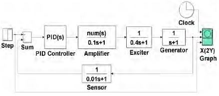
The excitation system of a synchronous generator is composed of an amplifier, an exciter, a generator and a sensor as displayed in Figure 1. Parameters of the transfer function of the system are configured such that ka= 10 & τ a= 0.1 for the amplifier, ke= 0.4 & τ e= 1 for the exciter, kg= 1 (depending on the load, this varies from 0.7 to 1.0) & τ g= 1 for the generator, and ks= 1 & τ s= 0.01 for the sensor [10].
3. Neural Networks Predictive Control
3.1 Predictive Control
Predictive control is one of the types to predict the estimated value prior to the plant. The predicted control value is obtained by using the predictive value of the model, the optimization function, and the control method. Given performance function roles to minimize predictive values during optimization process, the performance function given as below [21].
| (1) |
N1 & N2 : Constant values to indicate the following error and the relevant time range
Nu : Value indicating the time region on the control input
u′ : Provisional control input value to the neural networks
yr : Following target value
ym : Output value of the neural-networks model
The objective of Equation (1) is to define a control value based on a target value. Control values should continuously be updating in order to minimize the J value in the predictive control.
An updated method for finding the minimum value of J, which is presented in this paper, adopts gradient descent methods that obtain a minimum point by moving in the direction of the negative gradient of the given function. The gradient descent method can be illustrated with Equation (2) as follows,
| (2) |
where,
γ : Constant
: Change in J for the current control input
Future control input values are expressed as future control input vectors in Equation (3),
| (3) |
The objective function J given by Equation (4) is the first partial differential equation for U,
| (4) |
3.2 Structure of Neural Networks
In general, the nonlinear dynamic model equation is determined by the past data of the input and the output as shown in Equation (5).
| (5) |
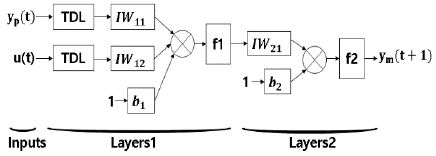
Therefore, in order to train the dynamic model equation using neural networks, a Time Delay Neural Network (TDNN) can be used as shown in Figure 2.
Considering the neural-network model, the input and output values of the plant are entered in the input part of the neural network, respectively, and each time-delay value is entered. The output of the neural network must be observed. The output of the neural network configured to learn the plant output value of the next sampling step that is that predictive control function is structured. The learning data necessary for the neural-network learning should be extracted from the results obtained by operating the plant.
The output of the TDNN model is depicted as,
| (6) |
and
| (7) |
3.3 Differential equation of a Neural Networks System
Generally, the output derivative for the processor input is calculated in order to apply the control theory,
| (8) |
Equation (9) can be transformed as follows,
| (9) |
Then,
| (10) |
| (11) |
Considering y(k − 1), y(k − 2),… y(k − n) values and that u(k − 1), u(k − 2),… u(k − m) are past values that are not influenced by u(k), Accordingly, all summation is zero except for j = 1,
| (12) |
| (13) |
Finally, Equation (12) and Equation (13) is an expression that TDNN neural network represents input & output characteristics. 3.4 Neural-Networks Predictive Control
Predictive control is a method of calculating the control input literally using the predicted value of the system. Therefore, if an appropriate neural-network model is selected and the learning is done well, the neural-network model can express the dynamic characteristics of the actual dynamic system well.
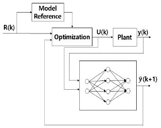
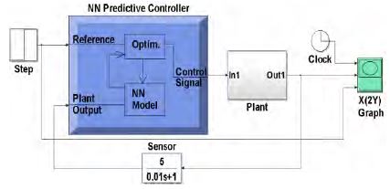
The prediction control algorithm can be constructed using the error between the reference input and the predicted value. Figure 3 is a block diagram illustrating the neural-network predictive control system.
k: Sampling time
r(k): Reference input signal
u(k): Control input value to the plant
y(k) : Output of the plant
e(k): Difference value (Error value) between r(k)& y(k)
: Predicted plant output
The control input value is calculated using the predicted value rather than the actual output value. By definition, the prediction controller minimizes the objective function J, and the objective function can be composed of error values as follows.
| (14) |
| (15) |
In order to improve the control performance, this study uses the gradient descent method as follows.
| (16) |
Using the J value and e(k + 1),
| (17) |
Considering TDNN,
| (18) |
| (19) |
The scalar values may be represented by prediction vectors as follows.
| (20) |
| (21) |
| (22) |
| (23) |
By definition, the prediction controller minimizes the objective function J, and the objective function can be expressed in terms of error values as follows,
| (24) |
To update the control performance, the gradient descent method is used as follows,
| (25) |
| (26) |
The Jacobian matrix is obtained as follows,
| (27) |
4. Simulation and result
4.1 PID control simulation and the result
Firstly, each gain of the PID control through the Ziegler Nichols tuning method in Figure 1 was measured as Kcr : 1.702, Pcr : 1.08, Kp : 0.54, Ti = 0.54 and Td = 0.135 as shown in Figure 4.
Secondly, PID controller parameters were acquired as 0.172486 for P gain, 0.167368 for I gain, 0.020729 for D gain and 5.172102 for the filter coefficient (N) using the automatic tuning method.
The compensator formula is given as follows,
| (28) |
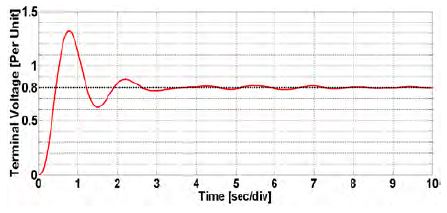
As shown in Figure 5, automatic tuning of the PID control of the synchronous generator resulted in values of 0.863 s for the rise time, 3.08 s for the settling time, and 8.23% for the overshoot being obtained.
4.2 NN Predictive control simulation and the result
The Simulink Model of the plant in Figure 6 includes the same transfer functions of a synchronous generator.
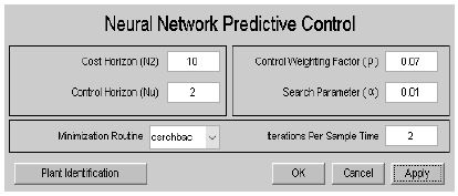
The parameter input for the NN predictive controller was set as in Figure 7. N2 of cost horizon enters 10 for time steps that predicted errors are minimum. ρ, Nu of control horizon, is 2 that control increasement values are minimized. The search parameter was 0.001 for the determination of the line search. The minimization routine used was csrchbac.
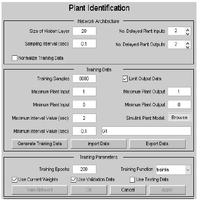
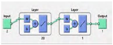
The synchronous generator plant model network was 20 at the first layer as seen in Figure 8. The training function was trainlm which refers to Levenberg-Marquardt. Furthermore, the objective function was Mean Square Error.
As shown in Figure 9, after training the neural-networks predictive control, the configuration was obtained.
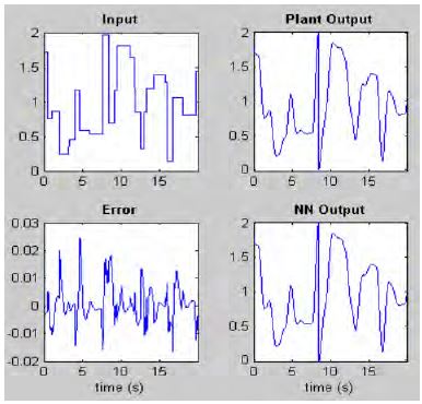
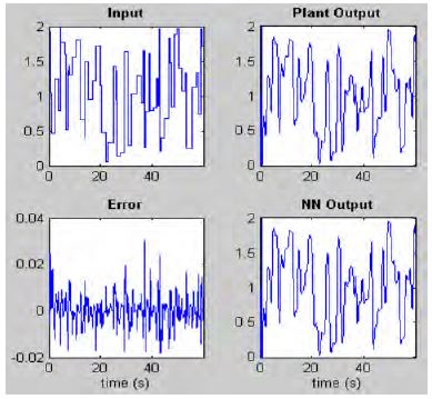
Following the completion of the training of the system, training performance could be comparatively shown between Figure 10 and Figure 11.
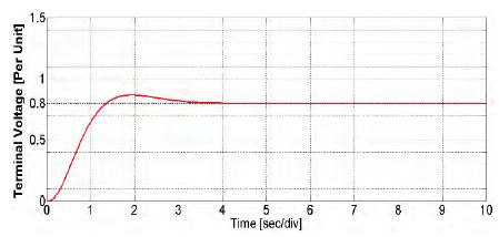
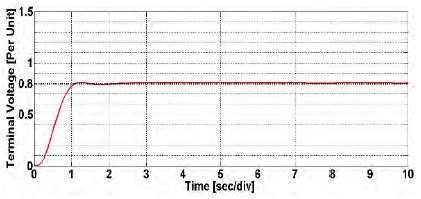
By using NN predictive control in a synchronous generator, the result in Figure 12 was acquired. Through the proposed control method, 0.58 s for the rise time, 1.02 s for the settling time, and 0.23% for the overshoot on the system were obtained.
5. Conclusion
Frequent changes in voltage cause damage to electric and electronic devices through switching loss and thermal loss. Therefore, maintaining the specified voltage in a power system is important. A range of equipment, such as automatic voltage regulators, power system stabilizers and filters, can be used to keep the voltage of a power system stable.
This paper dealt with the control method of the automatic voltage regulator of a synchronous generator. To verify the validity of the proposed method, the results obtained were compared with those obtained using PID control.
Following computer simulations, the terminal voltage from PID control is measured with 0.863 s for the rise time, 3.08 s for the settling time, and 8.23% for the overshoot. The proposed method measured 0.58 s for the rise time, 1.02 s for the settling time, and 0.23% for the overshoot. Through the use of the proposed control method, therefore, output voltage was improved 48% for rise time and 3.02 times for setting time and 10% for overshoot. This paper verified that the output voltage of the synchronous generator using neural-networks predictive control can be improved compared to that obtained using PID control.
Acknowledgments
This work was supported by the Korea Maritime And Ocean University Research Fund.
References
- L. D. S. Coelho, “Tuning of PID controller for an automatic regulator voltage system using chaotic optimization approach”, Chaos, Solitons & Fractals, vol. 39(no. 4), p1504-1514, (2009).
-
S. Kansit, and W. Assawinchaichote, “Optimization of PID controller based on PSOGSA for an automatic voltage regulator system”, Procedia Computer Science, vol. 86, p87-90, (2016).
[https://doi.org/10.1016/j.procs.2016.05.022]

-
H. Shayeghi, A. Younesi, and Y. Hashemi, “Optimal design of a robust discrete parallel FP+FI+FD controller for the Automatic Voltage Regulator system”, International Journal of Electrical Power & Energy Systems, vol. 67, p66-75, (2015).
[https://doi.org/10.1016/j.ijepes.2014.11.013]

-
S. Panda, B. K. Sahu, and P. K. Mohanty, “Design and performance analysis of PID controller for an automatic voltage regulator system using simplified particle swarm optimization”, Journal of the Franklin Institute, vol. 349(no. 8), p2609-2625, (2012).
[https://doi.org/10.1016/j.jfranklin.2012.06.008]

- F. Naeim, and T. Bingqi, “Application of self-tuning PID controller on the AVR system”, Proceedings of 2012 IEEE international Conference on Mechatronics and Automation, p2510-2514, (2012).
- J. H. Abdullah, M. A. Kaml, K. J. Mahmoud, and M. W. Mustafa, “Integrated PLC-fuzzy PID Simulink implemented AVR system”, International Journal of Electrical Power & Energy Systems, vol. 69, p313-326, (2015).
-
I. Szuvovivski, T. S. P. Fernandes, and A. R. Aoki, “Simultaneous allocation of capacitors and voltage regulators at distribution networks using Genetic Algorithms and Optimal Power Flow”, International Journal of Electrical Power & Energy Systems, vol. 40(no. 1), p62-69, (2012).
[https://doi.org/10.1016/j.ijepes.2012.02.006]

-
S. Panda, and K. Y. Narendra, “Automatic generation control of multi-area power system using multi-objective nondominated sorting genetic algorithm-II”, International Journal of Electrical Power & Energy Systems, vol. 53, p54-63, (2013).
[https://doi.org/10.1016/j.ijepes.2013.04.003]

- A. G. Suri babu, and B. T. Chiranjeevi, “Implementation of fractional order PID controller for an AVR system using GA and ACO optimization techniques”, IFAC-PapersOnLine, vol. 49(no. 1), p456-461, (2016).
- A. A. EL Ela, and S. R. Spea, “Optimal corrective actions for power systems using multi-objective genetic algorithms”, Electric Power Systems Research, vol. 79(no. 5), p722-733, (2009).
-
R. L. A. Ribeiro, C. M. S. Neto, F. B. Costa, T. O. A. Rocha, and R. L. Barreto, “A sliding-mode voltage regulator for salient pole synchronous generator”, Electric Power Systems Research, vol. 129, p178-184, (2015).
[https://doi.org/10.1016/j.epsr.2015.07.016]

-
L. B. Prasad, H. O. Gupta, and B. Tyagi, “Application of policy iteration technique based adaptive optimal control design for automatic voltage regulator of power system”, International Journal of Electrical Power & Energy Systems, vol. 63, p940-949, (2014).
[https://doi.org/10.1016/j.ijepes.2014.06.057]

-
S. Chatterjee, and V. Mukherjee, “PID controller for automatic voltage regulator using teaching-learning based optimization technique”, International Journal of Electrical Power & Energy Systems, vol. 77, p418-429, (2016).
[https://doi.org/10.1016/j.ijepes.2015.11.010]

-
V. Rajinikanth, and S. C. Satapathy, “Design of controller for automatic voltage regulator using teaching learning based optimization”, Procedia Technology, vol. 21, p295-302, (2015).
[https://doi.org/10.1016/j.protcy.2015.10.032]

-
G. Q. Zeng, J. Chen, Y. X. Dai, L. M. Li, C. W. Zheng, and M. R. Chen, “Design of fractional order PID controller for automatic regulator voltage system based on multi-objective extremal optimization”, Neurocomputing, vol. 160, p173-184, (2015).
[https://doi.org/10.1016/j.neucom.2015.02.051]

-
N. Aguila-Camacho, and M. A. Duarte-Mermoud, “Fractional adaptive control for an automatic voltage regulator”, ISA Transactions, vol. 52(no. 6), p807-815, (2013).
[https://doi.org/10.1016/j.isatra.2013.06.005]

-
M. Asama, H. Ukai, M. Sone, and K. Nakamura, “DSPBASED H∞ controlled Digital Automatic Voltage Regulator for use on Engine Generator”, IFAC Proceedings Volumes, vol. 35(no. 1), p283-288, (2002).
[https://doi.org/10.3182/20020721-6-es-1901.00381]

- M. Fasai, K. J. Zachariah, and J. W. Finch, “Implementation of a self-tuning AVR, IEE Proceedings of Control Theory Application”, vol. 144(no. 1), p32-39, (1997).
-
H. Gozde, and M. C. Taplamacioglu, “Comparative performance analysis of artificial bee colony algorithm for automatic voltage regulator (AVR) system”, Journal of the Franklin Institute, vol. 348(no. 8), p1927-1946, (2011).
[https://doi.org/10.1016/j.jfranklin.2011.05.012]

-
L. N. Magangane, and K. A. Folly, “Neuro-controllers for Synchronous Generator”, Proceedings of the 19th World Congress The International Federation of Automatic Control, p8218-8222, (2014).
[https://doi.org/10.3182/20140824-6-za-1003.00768]

- B. R. Lee, Fuzzy Neural Network Focusing on Matlab/Simulink, UUP, p211-217, (2012), (in Korean).

