Compact microstrip feed dual band monopole antenna for UWB and bluetooth applications
Copyright © The Korean Society of Marine Engineering
This is an Open Access article distributed under the terms of the Creative Commons Attribution Non-Commercial License (http://creativecommons.org/licenses/by-nc/3.0), which permits unrestricted non-commercial use, distribution, and reproduction in any medium, provided the original work is properly cited.
Abstract
This paper presents a small printed monopole antenna for ultra-wide band (UWB) (3.1~10.6 GHz) and Bluetooth (2.4~2.48 GHz). The proposed antenna consists of a small U-shaped UWB radiating patch and a lollipop-shaped Bluetooth radiating patch. This antenna is fed by a microstrip line and built by RF-4 dielectric substrate having a thickness of 1.6 mm. The size of the designed antenna is 15 × 26 ㎟, which is significantly smaller than the previous similar antenna. The simulated and measured results show that the proposed antenna achieves a broad operating bandwidth of 2.95~11.5 GHz for UWB application, and 2.38~2.52 GHz for Bluetooth application. The designed antenna has an omnidirectional radiation patterns and stable gain.
Keywords:
Monopole antenna, UWB, Bluetooth, Small size, U-shaped, Lollipop-shaped1. Introduction
Recently, UWB radio technology has attracted considerable attention for many applications since the Federal Communications Commission (FCC) released an unlicensed 3.1~10.6 GHz frequency band for UWB applications [1]. Many research groups have reported on types of UWB antennas [2]-[4]. In particular, the printed monopole antenna attracted many
researchers in the past few years owing to its physical features, such as its simple structure, small size, low cost, and ease of fabrication [5]-[7].
Nowadays, communication systems require a single antenna to cover several frequency bands. As an example of such a multi-band antenna, a single antenna covering the UWB band and the Bluetooth band have been reported. Yildirim presented an antenna that minimizes the interaction between UWB and Bluetooth resonance [8], and another paper written by Mahamine presents an antenna inserting a quarter wavelength strip in the middle part of radiating patch to achieve Bluetooth and UWB bands [9].
In this paper, a compact microstrip feed dual-band monopole antenna with a U-shaped slot and a lollipop-shaped strip is proposed for Bluetooth and UWB applications. The simulation and measured results for the return loss, radiation patterns and gain of the proposed antenna are shown.
2. Antenna Design
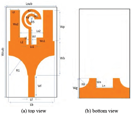
The designed monopole antenna and the parameters of the antenna size are shown in Figure 1, and Table 1, respectively. The antenna was designed on an FR-4 dielectric substrate with a dielectric constant of 4.4 and a thickness of 1.6mm, and the characteristics of the antenna were simulated using HFSS software.
For a printed patch antenna, the current mostly flows to the edge of the patch. Therefore, even if the upper center portion of the patch is cut out and deformed into a U-shape, there is no significant influence on the characteristics of the patch antenna. Therefore, the antenna for Bluetooth was designed in the Ushaped cut - out space. The impedance bandwidth of the print antenna was decided by the shape of radiating patch and ground plane. To achieve the impedance bandwidth over the entire UWB range, two slots with same arc radius and another two rectangular slots were cut in the radiating patch, and three slots were cut in the ground plane, as shown in Figure 1.
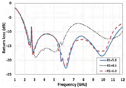
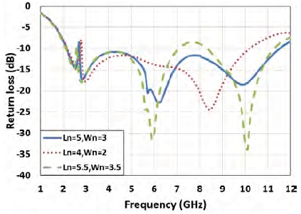
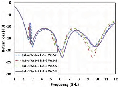
Figure 2 shows the return loss varying with different sizes of slots in the radiating patch, Figure 3 shows the return loss varying with different sizes of slot in the middle of ground, and Figure 4 shows the simulated return loss according to the parameters Ls1, Ws1, Ls2, and Ws2 of the proposed antenna. From Figure 2 to Figure 4, it can be seen that the return loss of the antenna largely changes according on the values of R1, Ln and Wn. In the simulation, the remaining parameters except for the variables are fixed to the values listed in Table 1.
A lollipop-shaped strip was inserted in the middle-notched part of the radiating patch to resonate at the Bluetooth band. The length of the lollipop-shaped strip could be obtained to create a monopole with length LB having a quarter wavelength of the Bluetooth frequency.
From Table 1, the length LB is 33.9 mm which is approximately 0.27λ at 2.4GHz.
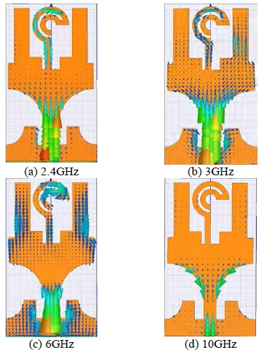
Figure 5 shows the current distribution of the designed antenna. It can be observed in Figure 5 (a) that the Bluetooth frequency is based on the lollipop-shape in the top of the antenna. The U-shape of the radiating patch supplies the UWB frequency, which is presented in Figure 5 (b), Figure 5 (c), Figure 5 (d). In addition the slot in the middle of the ground had a significant effect on the frequency bandwidth from 3~6 GHz, which can be seen in Figure 5 (b) and Figure 5 (c). Figure 5 (d) shows that the two slots of radiating patch control the return loss at high frequency.
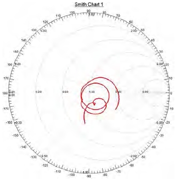
Figure 6 shows the simulated input impedance response of the designed multiband antenna.
3. Experimental Results
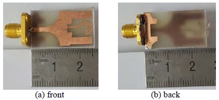
Figure 7 shows a picture of the fabricated monopole antenna on an FR-4 dielectric substrate with a thickness of 1.6 mm. From Figure 7, we can find that the proposed antenna is easy to fabricate and that the size of the antenna is very small.
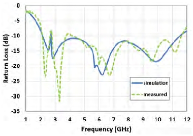
Figure 8 shows the simulated and measured return loss of the fabricated antenna. It shows that measured result fit well with the simulated result. It can be seen that the impedance bandwidth of the designed antenna is 2.95~11.5 GHz which covers the UWB frequency range, and 2.38~2.52 GHz which covers the Bluetooth frequency range.
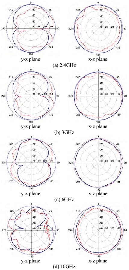
Figure 9 shows the simulated and measured radiation patterns in the E-plane (y-z plane) and H-plane (x-z plane). The radiation patterns are measured in an anechoic chamber of 10m × 5m × 6m using standard horn antenna. It can be seen that the measured radiation patterns fit well with the simulation results, and that the radiation patterns are nearly omnidirectional.
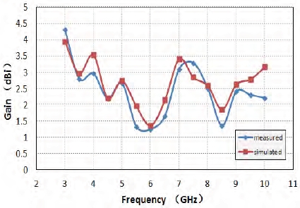
Figure 10 shows the simulated and measured maximum gain results of the design antenna. Moreover, it can be seen that the antenna gains change in the range from 1.2 dBi to 4.3 dBi within the frequency range from 3 GHz to 11 GHz. In Figure 10, the antenna gain at 6 GHz is smaller than that at the other frequencies. This is the result of the current flowing in opposite directions on the antenna surface more than that in other frequencies.
4. Conclusion
A small printed monopole antenna for UWB and Bluetooth applications was proposed in this paper. The lollipop-shaped strip was used to achieve the Bluetooth signal without affecting the UWB signal, which was supplied by the U-shaped patch. The two cuts with same radius in the U-shaped patch and the three cuts in the ground plane provided a good impedance match. The designed antenna was fabricated using a FR-4 dielectric substrate with a thickness of 1.6 mm, and the size of the antenna was 15mm× 26mm × 1.6mm , which is very small compared to the size of the antenna presented in other papers [8][9]. The measured results fit well to the simulation results, the radiation characteristics were acceptable in the working bandwidth, and this antenna exhibited omnidirectional radiation patterns.
References
- FCC, Ultra-wideband Operation FCC Report and Order, Tech.rep.US47 CFR Part 15, (2002).
-
Z. N. Chen, Terence S. P. See, and X. Qing, “Small Printed ultra-wideband antenna with reduced ground plane effect”, IEEE Transactions on Antennas and Propagation, vol. 55(no. 2), p383-388, (2007).
[https://doi.org/10.1109/TAP.2006.889823]

-
M. Ojaroudi, N. Ojaroudi, and N. Ghadimi, “Dual bandnotched small monopole antenna with novel coupled inverted U-ring strip and novel fork-shaped slit for UWB applications”, IEEE Antennas and Wireless Propagation Letters, vol. 12, p182-185, (2013).
[https://doi.org/10.1109/LAWP.2013.2245296]

-
A. Garg, D. Kumar, P. K. Dhaker, and I. B. Sharma, “A novel design dual band-notch small square monopole antenna with enhanced bandwidth for UWB application”, IEEE International Conference on computer, Communication and Control, p1-5, (2015).
[https://doi.org/10.1109/IC4.2015.7375542]

-
S. Kundu, M. Kundu, and K. Mandal, “Small monopole antenna with corner modified patch for UWB applications”, 2014 First International Conference on Automation, Control, Energy and Systems, p1-3, (2014).
[https://doi.org/10.1109/ACES.2014.6807975]

-
A. Singh, and R. K. Raj, “Dual band notched small monopole antenna with a novel T-shaped slot for UWB applications”, IEEE International Conference on Advances in Engineering and Technology Research, p1-4, (2014).
[https://doi.org/10.1109/ICAETR.2014.7012908]

-
A. Bekasiewicz, and S. Koziel, “Structure and computationally efficient simulation-driven design of compact UWB monopole antenna”, IEEE Antennas and Wireless Propagation Letters, vol. 14, p1282-1285, (2015).
[https://doi.org/10.1109/LAWP.2015.2402282]

-
B. S. Yildirim, and B. A. Cetiner, “Integrated bluetooth and UWB antenna”, IEEE Antennas and Wireless Propagation Letters, vol. 8, p149-152, (2009).
[https://doi.org/10.1109/LAWP.2009.2013371]

-
S. D. Mahamine, and R. P. Labade, “A ‘ϕ ’ shaped compact dual band printed monopole antenna for bluetooth and UWB applications”, 2015 International Conference on Industrial Instrumentation of Control, p756-760, (2015).
[https://doi.org/10.1109/IIC.2015.7150843]


