RCGA based PID controller with feedforward control for a heat exchanger system
Copyright © The Korean Society of Marine Engineering
This is an Open Access article distributed under the terms of the Creative Commons Attribution Non-Commercial License (http://creativecommons.org/licenses/by-nc/3.0), which permits unrestricted non-commercial use, distribution, and reproduction in any medium, provided the original work is properly cited.
Abstract
A heat exchanger is commonly used in a chemical process and/or ships to transfer heat from a hot fluid through a solid wall to a cooler fluid. Various types of PID controllers have been adopted to control the temperature of a heat exchanger to guarantee control performance. The inherent limitation of PID controllers, however, is that the controller acts after disturbance distorts the required control objective. If disturbances occur frequently, a PID controller would not be able to attain the desired steady state response. To overcome this limitation, feedforward control must be adopted with PID control. Feedforward control works in combination with PID control as it cannot operate alone. This paper presents a method to control the temperature of a heat exchanger by using a PID controller with a feedforward controller. The parameters of the PID controller are tuned using the real-coded genetic algorithm (RCGA) by minimizing the integral absolute error. A set of simulations are carried out to compare the set-point tracking and disturbance rejection performances of the proposed controller with conventional PID controllers.
Keywords:
Heat exchanger, PID controller, Feedforward controller, RCGA1. Introduction
A heat exchanger is widely used in chemical plants and/or ships because it can sustain a wide range of temperatures and pressures. There are different types of heat exchangers, but a shell and tube heat exchanger system is most widely used [1]. The main purpose of a heat exchanger system is to transfer heat from a hot fluid to a cooler fluid; thus, controlling the temperature of the outlet fluid is of prime importance. An accurate mathematical model is required to design a controller. However, it is difficult to obtain a suitable mathematical model because the dynamics of a heat exchanger depends on many factors such as temperature difference, heat transfer area, flow rate of fluids, and flow patterns. Various studies have proposed different temperature control methods for heat exchangers such as feedforward PID control [2], optimal linear fuzzy control [3], PI type fuzzy control [4], PID controller, and internal model control [5][6].
PID control is a classical method, and it has been studied for the last several decades and is widely used in the field. The inherent limitation of a PID controller, however, is that the controller acts after disturbance distorts the required control objective. If disturbances occur frequently, a PID controller would not be able to attain the desired steady state response. To overcome this drawback, feedforward control must be adopted with PID control.
This paper presents a linear PID controller with feedforward control that shows a better control performance and systematic tuning than conventional PID controllers. The temperature control of the heat exchanger may cause time delays and disturbances; thus a PID controller combined with a feedforward controller is designed to improve control performance.
The parameter tuning methods of the PID controller include the closed-loop and open-loop tuning methods such as the Z–N (Ziegler–Nichols) tuning method, IMC (Internal Model Control) tuning method, and RCGA (Real Coded Genetic Algorithm) tuning method [7]-[9]. Among them, the RCGA tuning method provides an optimal solution by using the evaluation function under given conditions. This study, therefore, uses the RCGA technique to tune the PID controller. In order to improve the tracking performance of the control system, the PID controller is tuned while the disturbance is fixed, and the set value is changed stepwise. Further, the PID controller tuned by RCGA and a feedforward controller are combined to examine disturbance rejection while the measured disturbance is applied to the heat exchanger system.
A set of simulations are carried out to compare set-point tracking and disturbance rejection performances with conventional PID controllers and show the feasibility of the proposed method.
2. Modeling of heat exchanger
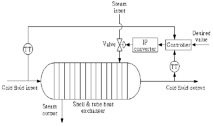
Figure 1 shows the temperature control system of the shell and tube heat exchanger used in industrial fields. This system consists of a heat exchanger, a controller, an I/P converter, a control valve, and a temperature transmitter (TT). Overheated steam at a temperature of 180 [℃] supplied from the boiler flows into the tubes after the control valve adjusts the amount of steam. On the other hand, fluid at a temperature of 30 [℃], pumped by a centrifugal pump, flows through the shell. These conditions are assumed to be equilibrium states for simulations.
Different assumptions have been considered in this study. The first assumption is that the inflow and outflow rates of fluid are same, so that the level of fluid is constant in the heat exchanger. The second assumption is that the heat storage capacity of the insulating wall is negligible.
The inlet and outlet temperatures measured by a thermocouple are converted to current signals from 4 [mA] to 20 [mA] and are implemented in the feedback path of the control system.
The controller implements the control algorithm, compares the cold fluid output with the desired value, and then provides the necessary command to the final control element (valve) via the actuator unit. The actuator unit is a current-to-air pressure converter, and the final control unit is an air-to-open (fail-close) valve. The actuator unit converts the controller output within a range of 4-20 [mA] into a standardized air pressure signal within a range of 0.2-1.0 [bar]. The valve is actuated according to the controller decisions.
The experimental data available for the heat exchanger system is summarized in other studies [10][11]. A linearized mathematical model of heat exchanger is developed from the experimental data.
2.1 Saturator
There is a physical limit to the operation of an actual actuator. Therefore, to approach a more realistic problem, a saturator is considered and expressed as Equation (1).
| (1) |
um and uM indicate the minimum and maximum values of the saturator, respectively.
2.2 Actuator
An actuator is a device that uses electricity, hydraulic pressure, air pressure etc. to perform proper operation for input signal. The actuator consists of an I/P converter that converts an electrical signal into a pneumatic signal and a control valve. The transfer function can be expressed as a first order system as follows.
| (2) |
Usat and Ua are the outputs of the saturator and actuator, respectively. KIP is the I/P converter gain and kv is the control valve gain. Ka is the actuator gain and τa is the time constant of the actuator.
2.3 Heat exchanger
The transfer function of the heat exchanger can be expressed as a first order system with time delay by using Equation (3).
| (3) |
kx and τx are the gain and time constants of the heat exchanger, respectively, and L represents the time delay.
2.4 Sensor
The transfer function of the sensor can be expressed as a first order system as follows.
| (4) |
ks and τs are the gain and time constants of the sensor, respectively.
2.5 Disturbance
Assuming that the transfer function does not have a time delay, Gd(s) can be expressed as a first order system as follows.
| (5) |
kd and τx are the gain and time constants of disturbance, respectively. Further, it is assumed that τx is equal to the time constant of the heat exchanger.
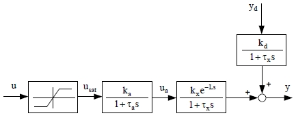
Figure 2 shows the control system consisting of a saturator, actuator, and heat exchanger and the disturbance.
This can be expressed by the following equation.
| (6) |
Y(s) is the outlet temperature of the fluid, and Ys(s) is the inlet temperature of the fluid under disturbance.
Table 1 summarizes the various parameters used in this study. The minimum and maximum values of the actuator are 4 [mA] and 20 [mA], respectively.
3. PID controller combined with feedforward controller
3.1 PID controller
A conventional linear controller is used as a PID controller, and its transfer function is expressed as follows.
| (7) |
Kp, Ti and Td are the proportional gain, integral time, and derivative time, respectively.
There are different tuning methods of a PID controller. Some methods are empirical methods, some methods are based on frequency response analysis, and other methods are based on the minimization of performance measures. Despite advances, most PID controllers are tuned using the trial and error method.
3.2 Feedforward controller
The inherent limitation of a feedback controller is that the controller acts after disturbance distort the required control objective. If disturbances occur frequently, the PID controller would not be able to attain the desired steady state response. To overcome this limitation, feedforward control must be adopted with PID control. Feedforward control limits the deviation caused by the disturbance while it works under the condition that the disturbance would be measured or estimated. Feedforward control works in combination with feedback control, as it cannot operate alone.
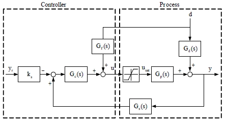
Figure 3 shows a control system incorporating the feedforward controller. In this system, the closed-loop transfer function of the output temperature under disturbance is as follows.
| (8) |
Gf(s) is the transfer function of the feedforward controller. Gp(s) is the transfer function of the actuator and heat exchanger.
In case the numerator of Equation (8) becomes 0, the disturbance can be removed.
| (9) |
Rewriting the above equation, the transfer function of the feedforward controller is as follows.
| (10) |
Because there is a time delay in Gp(s) , the order of the numerator is larger than that of the denominator in Gf(s) . In order to replace the time delay, (1+λs)n is added in the denominator of Gf(s) , and then, Equation (10) is expressed as follows.
| (11) |
λ is the filter time constant, and its value varies between 0 and 1. In this paper, λ was set to 0.9 and n to 1 through trial and error.
4. Tuning of the PID controller
4.1 Z–N tuning technique
The Z–N technique presented in this paper repeats trial and error by using the MATLAB software. The limit gain was 16.50, and the limit cycle was 34.46 [s] at this time.
4.2 IMC tuning technique
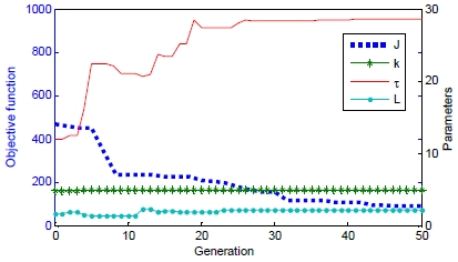
In order to use the IMC technique, the transfer function of the plant have to be given by the FOPTD (First Order Plus Time Delay) system. Figure 4 shows the process of searching k, τ, and the L values of FOPTD obtained using RCGA, and we can obtain k = 4.976, τ = 28.557, L = 2.228.
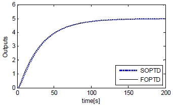
Figure 5 shows the step response for the SOPTD(Second Order Plus Time Delay) system and FOPTD system as the approximated model. Comparing the two responses shows that the step responses showed good agreement.
4.3 RCGA-based tuning technique
First, in order to improve the tracking performance, the parameters of the PID controller are tuned while the disturbance is fixed and the set value is changed stepwise.
This paper proposes RCGA as a tuning method and the IAE(Integral Absolute Error) is used as an evaluation function.
| (13) |
φ is [Kp, Ki , Kd]∈ R3 and e(t) is the error between the set value and the output, and the integration time tf is a sufficiently large value enough to ignore integral values thereafter.
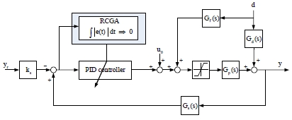
Because optimization techniques operate on a probabilistic basis in general, the solutions obtained vary slightly depending on the configuration of the initial group. Therefore, in order to ensure that the solution searched with RCGA is optimal, simulations are performed five time by using random seed values, and the average value of the results is determined as final solutions. Figure 6 shows the concept of searching each parameter of the PID controller by RCGA.
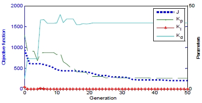
In order to obtain ing the optimal parameter using RCGA, the number of generations, population, crossover, mutation were set to 50, 30, 0.9 and 0.05, respectively. Figure 7 shows the process of searching Kp, Ki , Kd of the PID controller using RCGA.
Table 2 summarizes the parameters obtained from the proposed technique and the other techniques.
5. Simulation and review
In order to validate the proposed controller, simulations were performed with the sampling time of 0.01[s], and the proposed controller was compared with the Z–N and IMC technique.
5.1 Tracking performance of PID controller
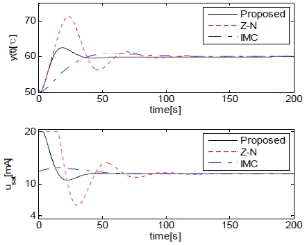
Figure 8 shows the outputs and control inputs when the set value is changed from 50 [°C] to 60 [°C], under the assumption that disturbance does not exist.
Table 3 summarizes the rising time, overshoot, setting time and absolute error integration.
From Figure 8 and Table 3, it can be seen that rising time of the Z–N technique is the shortest, while the overshoot value and settling time are very large. The overshoot value of the IMC technique is slightly smaller than those of other methods, but the rising and settling times are very large. The overshoot value of the proposed RCGA technique is very similar to that of other techniques, while the rising and settling times are very small, corresponding to excellent results.
5.2 Disturbance rejection performance of PID controller without feedforward controller
In the above discussion, it was found that the RCGA-based PID controller has a relatively good performance in the tracking problem compared with other methods.
Next, simulation is performed to examine the disturbance rejection performance when a measured disturbance is applied to the heat exchanger system. The temperature of cold fluid is assumed to decrease stepwise from 30 [°C] to 20 [°C] after 50[s]. Figure 9 shows the control results, and Table 4 summarizes MV (maximum variation) and MV time, recovery time, and absolute error integration.
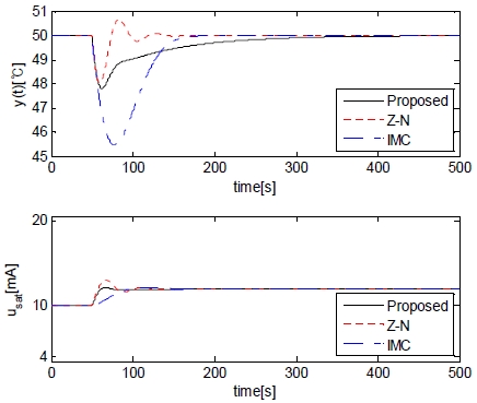
Disturbance rejection responses without feedforward controller when d decreases stepwise from 30 [°C] to 20 [°C]
5.3 Disturbance rejection performance of PID controller combined with feedforward controller
Because the feedforward controller does not affect the tracking performance, the disturbance rejection performance with feedforward controller is shown intensively in Figure 10.
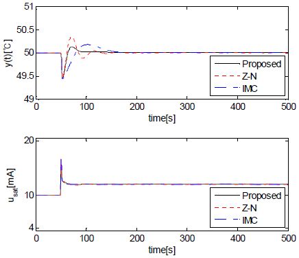
Disturbance rejection responses with feedforward controller when d is step-wisely decreased from 30 [°C] to 20 [°C]
Table 5 summarizes the MV and MV time, recovery time, and absolute error integration.
According to Figure 9 and Figure 10, the PID controller combined with the feedforward controller shows better disturbance rejection performance. Especially, the RCGA-based PID controller shows excellent disturbance rejection performance when the feedforward controller is combined.
From these simulations, it is clear that a PID controller combined with a feedforward controller is a much better option for disturbance rejection control problem rather than conventional PID control.
6. Conclusion
This paper implemented a conventional PID controller and a PID controller with a feedforward controller to control the outlet temperature of a shell and tube heat exchanger system. A mathematical model of the heat exchanger was developed using experimental data of previous studies. The parameters of the PID controller were tuned using the RCGA technique. The performance of the controllers was evaluated using transient characteristics and error indices. From the simulation results, it was found that the performance of the RCGA-based PID controller combined with the feedforward control was superior under disturbance.
The classical PID controller showed a higher MV and MV time whereas the RCGA-based PID controller with feedforward controller reduced the MV, MV time and also obtained a good recovery time.
References
- T. N. L. Vu, J. T. Lee, and M. Y. Lee, “Design of multi-Loop PID controllers based on the generalized IMC-PID method with Mp criterion”, International Journal of Control, Automation, and Systems, vol. 5(no. 2), p212-217, (2007).
- N. K. Navid, A. Sakhvati, and S. H. Hosseini, “Design of a PID feed-forward controller for controlling output fluid temperature in shell and tube heat exchanger”, Journal of Electrical and Electronic Engineering, vol. 3(no. 2-1), p30-34, (2015).
-
A. Maidi, M. Diaf, and J. P. Corriou, “Optimal linear PI fuzzy controller design of a heat exchanger”, Chemical Engineering and Processing: Process Intensification, vol. 47(no. 5), p938-945, (2008).
[https://doi.org/10.1016/j.cep.2007.03.008]

- M. Pandey, K. Ramkumar, and V. Alagesan, “Design of fuzzy logic controller for a cross flow shell and tube heat- exchanger”, IEEE-International Conference On Advances In Engineering, Science And Management, p150-154, (2012).
- S. Padhee, “Controller design for temperature control of heat exchanger system: Simulation studies”, WSEAS Transactions on Systems and Control, vol 9, p485-491, (2014).
-
G. M. Sarabeevi, and B. M. Laila, “Temperature control of shell and tube heat exchanger system using internal model controllers”, 2016 International Conference on Next Generation Intelligent Systems, p1-6, (2016).
[https://doi.org/10.1109/ICNGIS.2016.7854015]

- G. G. Jin, Genetic Algorithms and Their Applications, Kyowoosa, (2010).
-
Y. H. Lee, S. K. Kwon, and M. Y. So, “Design of RCGA-based PID controller for two-input two-output system”, Journal of the Korean Society of Marine Engineering, vol. 39(no. 10), p1031-1036, (2015).
[https://doi.org/10.5916/jkosme.2015.39.10.1031]

-
S. S. Shin, J. H. Noh, and J. H. Park, “A study on the optimal tuning of the hydraulic motion driver parameter”, Journal of the Korean Society of Marine Engineering, vol. 38(no. 1), p39-47, (2014), (in Korean).
[https://doi.org/10.5916/jkosme.2014.38.1.39]

- S. Padhee, and Y. Singh, “A comparative analysis of various control strategies implemented on heat exchanger system: A case study”, Proceedings of the World Congress on Engineering, vol. 2, p873-877, (2010).
-
S. Padhee, Y. B. Khare, and Y. Singh, “Internal model based pid control of shell and tube heat exchanger system”, in IEEE Students’ Technology Symposium, p297-302, (2011).
[https://doi.org/10.1109/TECHSYM.2011.5783833]


