Zone heating method for the efficient use of energy in painting process for ship blocks and plant structures
Copyright © The Korean Society of Marine Engineering
This is an Open Access article distributed under the terms of the Creative Commons Attribution Non-Commercial License (http://creativecommons.org/licenses/by-nc/3.0), which permits unrestricted non-commercial use, distribution, and reproduction in any medium, provided the original work is properly cited.
Abstract
This paper proposes a method of air conditioning in workspaces, which increases productivity and reduces the cost involved in the painting process of ship blocks and plant parts. The costs of electricity, LNG, LPG, diesel, and kerosene as energy sources for the process are compared. A zone heating method for heating the painting target is suggested instead of the conventional method of heating the entire plant. In providing the required painting conditions during summer, heating saves more in terms of energy and system costs, when compared to dehumidifying. An impinging jet is recommended for drying the painted surface to save time and energy. For the efficient use of thermal energy, a low air velocity and small-diameter for the jet are required. The optimum diameter of the jet and the distance between the target surface and jet are about 30 cm and 2.3 m, respectively.
Keywords:
Energy saving, Paint, Plant structure, Ship block, Drying, Heating1. Introduction
Painting is an important process in shipbuilding and plant construction [1]. The object to be painted usually weighs more than hundreds of tons; therefore, a large amount of time and energy are required for the process. The drying speed of the paint is one of the important parameters considered while preparing the process schedule. Environmental parameters such as temperature, humidity, dust, and ventilation are factors that affect the painting speed, cost, and quality. Due to the large scale, saving energy and maintaining uniform painting quality are essential as well.
The conventional method used to paint ship blocks involves heating and cooling the air of the entire plant, whose volume can be 30,000–500,000 m3. This results in an enormous cost in the painting process during winter and summer. The heating and drying processes rely on natural convection in the plant. Portable burners are frequently used to heat the target objects. C. S. Yim et al.[2] reported that infrared heaters are more effective than nichrome heaters in drying paint coats. However, due to the size of the ship blocks and plant parts, it is not easy to apply this method.
The purpose of the present work is to investigate cost savings and reduction in drying and dehumidifying times in the painting processes of ship blocks and plant parts. The energy source, methods of heating and air conditioning in summer and winter, and the nozzle specifications of an impinging jet for the process are discussed.
2. Painting Process
2.1 Drying Time of Paint
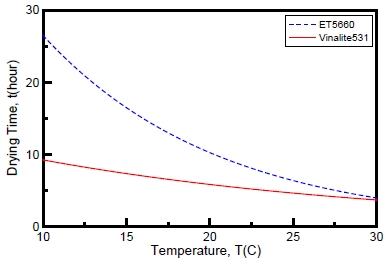
Figure 1 shows the relation between the drying time and ambient temperature for a typical epoxy (ET5660) and vinyl-acrylic based paint (VINALITE 531) [3]. The drying-time, which forms a large portion of the time duration for the painting process, decreases with increase in air temperature in the painting space. In addition, the surface to be painted usually requires a relative humidity of less than 80%; if this condition is not satisfied, the paint develops problems such as wrinkling, peeling, bubbling, and cracking.
2.2 Environmental Data
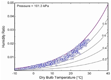
Figure 2 shows a psychrometric chart of the mean daily temperatures and humidity for workspace locations in the Gunsan area for the year 2013. The average temperature ranges from −5 °C with a relative humidity greater than 50% in winter to 30 °C with a relative humidity greater than 80% in summer. Therefore, the air in the painting spaces needs to be heated in the winter, spring, and autumn, and dehumidified in the summer.
2.3 Selection of Energy Source
Table 1 compares the costs of energy sources that were generally used in the Gunsan area during the year 2015: electricity, LNG, LPG, diesel, and kerosene. Kerosene, which is the most expensive, is 2.38 times as expensive as electricity, which is the cheapest, for the same thermal energy. Electricity also has advantages over gas and oil in terms of safety, system simplicity, and system management. Therefore, electricity is a strong candidate among the available energy sources for controlling the environment in the present system.

Comparison of the costs (in Korean won) of energy sources used in the Gunsan area for the year 2015: electricity, LNG, LPG, diesel, and kerosene [4]-[6].
The average energy ir needed to heat and dehumidify a unit of the painting space air from the environmental to the desired conditions during a period is obtained as follows:
| (1) |
where it and id are the target and environment enthalpies of the air, respectively, and n is the number of days considered in the period.
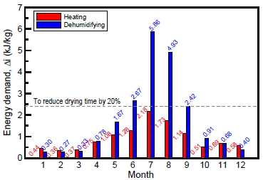
Figure 3 shows the average monthly heating load required to reduce the drying time of epoxy ET5660 by 20% in winter in the Gunsan area. The load Δi varies monthly in small increments, and the maximum is about 2.45 kJ/kg in July. In summer, the relative humidity can be reduced by heating or dehumidifying the air.
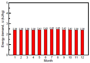
Comparison of energy required to control the temperature of the workspace to reduce the drying time of epoxy ET5660 by 20% in the Gunsan area in 2013.
Figure 4 shows the average monthly heating and dehumidifying energy loads that was needed to satisfy the 80% relative humidity requirement during the year 2013. The loads for the air vary monthly, and the maximum load required for dehumidifying was 5.86 kJ/kg in July. The energy needed for heating the air, to meet the requirements of the painting process from June to September, is about 40% of that for dehumidifying the air. Heating is useful for warming the air in all the seasons and for decreasing the relative humidity in summer. Therefore, electric heating devices are a very good choice from the perspectives of saving energy and capital costs as well as for mobility in the present system.
3. Design of Heating Device
3.1 Thermal Model
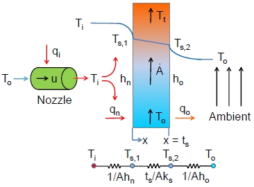
Impinging jets are widely used to control the temperature of surfaces exposed to an open space, because they provide high heat transfer coefficients. In the present case, the thickness of a steel sheet for a ship block is approximately 20 mm, and the thickness of the paint is approximately 0.1 mm. Therefore, the heat capacity of the paint layer is negligible compared to the steel sheet. Figure 5 shows the lumped thermal model of the present study for painting an object, usually a steel sheet, which is heated on one side and exposed to open space on the other. It is assumed that a cold steel sheet of thickness ts [m] in air at ambient temperature To is fed at a constant rate [m2/s], and the impinging jet heats it to the target temperature Tt uniformly. This process requires thermal loads on the moving steel sheet and impinging jet. The net thermal energy qs needed to heat the sheet to the target temperature can be calculated as follows:
| (2) |
where ρs and cp,s are the density and heat capacity of the steel sheet, respectively.
As shown in Figure 5, the ambient air at temperature To is heated to temperature Ti by applying qi , and the air with velocity u is ejected from the nozzle of the impinging jet with diameter D onto the steel sheet. The air from the jet on one side of the steel sheet, and the still air on the other side, have heat transfer coefficients hn and ho, respectively. The thermal resistances include the convection thermal resistance caused by the impinging jet, the conduction resistance of the steel sheet, and the natural convection thermal resistance on the opposite side. The Biot number of the steel sheet based on the thickness, hnt/2ks, is about 0.004 for heat transfer coefficient hn = 100 W/m2·K, even under severe conditions. Therefore, the steel may be considered as a lumped system whose temperature is almost constant along the thickness direction, i.e., Ts,1 ≈ Ts,2 ≈ Ts. The steel sheet is heated continuously from the ambient temperature To to the target temperature Tt, and therefore the average temperature of the steel sheet is assumed to be an arithmetic average in the present work:
| (3) |
The heat transfer coefficient for natural convection in stagnant air is about 5 W/m2·K. Therefore, the configuration of the impinging jet is very important to the heating speed of a steel sheet, and hence, the drying speed of the paint. The energy balance and heat transfer equations are given below:
| (4) |
| (5) |
| (6) |
where qn and qo are the heat transfers from the impinging jet to the steel sheet and from the steel sheet to the ambient air, respectively. If we assume natural convection for the air on a vertical disk with radius R, which is a specified heated zone, the heat transfer coefficient on the open space side can be expressed by the Churchill and Chu correlation [7]:
| (7) |
| (8) |
| (9) |
where Nuo, Rao, and Pr are the Nusselt, Rayleigh, and Prandtl numbers, respectively, and ρa, βa, κa, μa, and R are the density, thermal expansion coefficient, thermal conductivity, viscosity of the air, and radius of the steel respectively.
The thermal load at the nozzle achieves the desired impinging jet temperature from the ambient air, as given below:
| (10) |
where D and u are the nozzle diameter and air velocity of the impinging jet, respectively.
In the present work, the energy efficiency is defined as the ratio of the heat transferred to the steel sheet over the thermal load at the nozzle:
| (11) |
The efficiency depends strongly on the thermal resistance, i.e., the convection heat transfer coefficient between the impinging jet and the painting surface.
3.2 Heat Transfer Coefficient of Impinging Jet
The heat transfer coefficient of the impinging jet is a major parameter in the thermal resistance. Goldstein [8] expressed the average Nusselt number of the normal impinging jet on a steel sheet as
| (12) |
where A = 24, B = 533, C = 44, n = 1.285, and L, D, and R are the distance between the nozzle and object, nozzle diameter, and radius of the object (a steel sheet in the present work), respectively. The Nusselt and Reynolds numbers for the nozzle are defined as
| (13) |
| (14) |
where hn is the average heat transfer coefficient on the surface of the object.
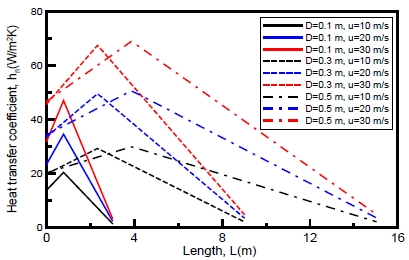
There are various shapes of ship blocks; therefore, the model ship block to be painted is considered to be a steel disk with a 20 mm thickness and 1 m radius (R). Figure 6 shows the graph of the heat transfer coefficient versus the distance between the nozzle and object for various nozzle diameters and air velocities. The heat transfer coefficient is a function of the distance, diameter, and velocity, and shows a maximum value at a certain distance. The maximum heat transfer occurs at L/D = 7.78, as expressed in Equation (12).
3.3 Energy Efficiency
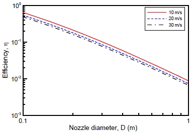
Figure 7 shows the net heat transfer rate as a function of the nozzle diameter and air velocity of the impinging jet. In this comparison, the ambient and nozzle temperatures and the ratio of the distance to the object over the nozzle diameter are fixed as 10 °C, 70 °C, and L/D = 7.76. The assumed steel feeding rate is 0.04 m2/s, which is estimated from the surface area that is painted monthly in the field. From the figure, the net heat transfer rate increases as the nozzle diameter and velocity increase, and the maximum net heat transfer rate is obtained at a nozzle diameter of 0.3 m. Figure 8 shows the graph of energy efficiency versus the nozzle diameter for different velocities. In fact, the efficiency increases as the nozzle diameter and velocity decrease. For given operating conditions of steel-feeding velocity and air and steel target temperatures, a small diameter and low velocity, with L/D ≈ 7.76, are recommended for maximum efficiency in the present study.
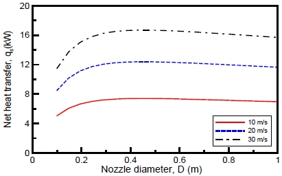
Net heat transfer versus nozzle diameter for 3 nozzle velocities under conditions of To = 10℃, Tn = 90℃ , A˙ = 0.04m2, ts = 0.02m, and L/D = 7.76
4. Concluding Remarks
This study was performed to reduce the energy cost and enhance the productivity of the painting process for ship blocks and plant parts. Our conclusions are as follows:
- (1) Electric heaters are more economical than burners using kerosene, natural gas, diesel, or propane.
- (2) To maintain the relative humidity below 80% in the workspace, heating consumes about 40% of the energy that dehumidifying does.
- (3) Impinging jets are effective for heating and dehumidifying sheet-steel painting targets. A simple thermal model is proposed to estimate the bulk sheet temperature, heat transfer rate, and energy efficiency. In the model, the ratio of the distance between the nozzle and object over the nozzle diameter is 7.76 for maximum energy efficiency. A small diameter nozzle and low air velocity are recommended for saving energy.
The present work investigated and designed a model for energy supply according to the weather conditions in Gunsan, Korea; however, the design can be adjusted for other locations. Currently, heat pumps are very effective devices for utilizing thermal energy. Heat pumps can save operation costs and have potential for the future. However, they also have some limitations in achieving high temperatures, and require large capital investments and lack mobility.
Acknowledgments
This work (Grants No. C0217527) was supported by Business for Cooperative R&D between Industry, Academy, and Research Institute funded by the Korea Small and Medium Business Administration in 2014.
References
-
K. A Dafforn, J. A. Lewis, and E. L. Johnston, “Antifouling strategies: History and regulation, ecological impacts and mitigation”, Marine Pollution Bulletin, vol. 62(no. 3), p453-465, (2011).
[https://doi.org/10.1016/j.marpolbul.2011.01.012]

- C. S. Yim, S. C. Ohu, K. S. Kim, N. C. Cho, and Y. J. Kim, “A study on drying of coated films utilizing infrared ray”, Solar Energy, vol. 14(no. 1), p7-15, (1994).
- Technical Data, Byucksan Paint and Coatings co., Ltd., (2015).
- Monthly Energy Statistics, Korea Energy Economics Institute, vol. 7, (2014).
- Price of Electricity, http://home.kepco.co.kr/kepco/main.do Accessed April 29, 2015.
- Price of Oil, http://www.oilandgas.co.kr Accessed April 29, 2015.
-
S. W. Churchill, and H. H. S. Chu, “Correlating equation of laminar and turbulent free convection from a vertical plate”, International Journal of Heat and Mass Transfer, vol. 18(no. 11), p1323-1329, (1975).
[https://doi.org/10.1016/0017-9310(75)90243-4]

-
R. J. Goldstein, A. I. Behbahani, and H. K. Kieger, “Streamwise distribution of the recovery factor and the local heat transfer coefficient to an impinging circular air jet”, International Journal of Heat and Mass Transfer, vol. 29(no. 8), p1227-1235, (1986).
[https://doi.org/10.1016/0017-9310(86)90155-9]


