반도체 웨이퍼 열공정에 사용되는 파워단자부의 전기-열 해석
Copyright © The Korean Society of Marine Engineering
This is an Open Access article distributed under the terms of the Creative Commons Attribution Non-Commercial License (http://creativecommons.org/licenses/by-nc/3.0), which permits unrestricted non-commercial use, distribution, and reproduction in any medium, provided the original work is properly cited.
초록
히터 플레이트의 강건성은 웨이퍼 공정의 신뢰도에 필수적이다. 하지만, 열적으로 유발되는 고장은 히터 모듈의 파워단자부에 빈번하게 발생한다. 따라서, 파워단자부의 열특성은 주의 깊게 조사되어야 하므로, 파워단자부의 유한요소해석 전기-열모델이 도출되었고, 측정에 의해 검증되었으며, 해석에 적용되었다. 모델을 활용하여 봉지재의 열전도율, 기판 두께, 발열부 면적이 열성능에 미치는 매개변수적 영향을 연구하였다. 기본 조건하의 파워단자부의 발열부는 기판대비 10K 고온이며, 1 K/mm 의 상당한 온도 구배가 발열부에서 발생됨이 밝혀졌고, 매개변수 영향 연구에 의해서는 봉지재 열전도율이 0.2 W/m-K 에서 5W/m-K 로 25배 증가해도 발열부 최대온도는 단지 0.6% 감소하는 미미한 봉지재 열전도율 영향이 밝혀졌다. 또한, 기판두께가 0.5mm에서 5mm로 증가 시 축방향 온도차는 61% 감소되는 상당한 기판 두께의 영향이 발견되었다. 반면에, 발열부 면적이 3배 증가할 때 최대온도는 0.5% 감소하는 상대적으로 미미한 발열부 면적 영향이 확인되었다.
Abstract
Robustness of heater plates is crucial for reliable wafer processing. Nevertheless, thermally-induced failures often occur at the packaged power terminals of heater modules. Hence, the thermal behaviors of the packaged power terminals should be carefully explored. Finite element analysis electrical-thermal models of the packaged power terminals were developed, validated by measurements, and then utilized for the analysis. The models investigated parametric influences including the thermal conductivity of the encapsulant, substrate thickness, and the area of the heating element on the thermal performance. The study has found that for the nominal conditions, a 10K higher temperature of the heating element compared with the substrate and a considerable axial temperature gradient of 1K/mm have occurred. The parametric study has found a negligible effect of the thermal conductivity of the encapsulant; though the thermal conductive of the encapsulant increases by 25 times, from 0.2W/m-K to 5W/m-K, the maximum temperature of the heating element decreases by only 0.6%. The study has also found that the effect of the substrate thickness is considerable; the axial temperature difference alleviates by 61% with the increase of the substrate thickness from 0.5mm to 5mm. However, the effect of the area of the heating element is found to be relatively moderate; the maximum temperature reduces by just 0.5% with the increase of the area of the heating element by 3 times.
Keywords:
Wafer, Packaged power terminal, Electrical-thermal, Heater plate, Finite element analysis키워드:
웨이퍼, 파워단자부, 전기-열, 히터 플레이트, 유한요소해석1. 서 론
반도체 제조공정에서 베이킹, 노광공정의 핵심모듈은 히터 플레이트(heater plate, HP) 이다[1]-[3]. HP는 감광액 도포 공정 시 웨이퍼 표면의 건조, 도포된 감광액의 베이킹, 노광시간 단축 등에 지대한 영향을 미치므로 일반적으로 온도 허용폭이 2°C 내로 요구되는 정교한 열처리 모듈이다. 따라서 HP의 온도 균일도를 확보하기 위한 연구는 지속적으로 수행되어왔다[1]-[7].
반면 HP는 가혹한 열공정 조건으로 인해 고장이 지속적으로 발생하며, 특히 파워단자부 (packaged power terminal, PPT)에서 빈번하게 열적고장이 발생하는데, 웨이퍼 열공정의 신뢰성을 향상시키기 위해서는 고장의 열적배경의 이해가 매우 중요하다. 하지만, 온도 균일도 확보 연구와 달리 이에 대한 연구는 매우 미흡한 상황이다. 따라서, 본 연구에서는 PPT의 열특성을 조사하고자 한다.
본 논문에서는 첫째, PPT의 유한요소해석 (FEA) 전기-열모델링에 대해서 논하고, 둘째 PPT 모델의 유효성 검증을 위한 테스트 리그와 검중결과에 대해 설명하며, 셋째, PPT 모델을 적용하여 수치적으로 해석된 PPT의 정량적 열특성과 매개변수 의존성에 대해서 논의하고자 한다.
2. FEA 전기-열 모델
2.1 기초이론
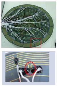
연구대상인 HP 와 PPT 의 실사는 Figure 1 에 제시 되어 있는데, HP 실사는 상단에, 실사에서 점선부분을 확대한 이미지는 하단에 제시된다. 하단의 이미지는 타원형 점선으로 표식된 PPT 한 쌍과 주변 열선을 명확하게 보여준다.
PPT의 열특성을 수치적으로 조사하기 위해서는 완전결합형 FEA 전기-열 모델이 필요하며, 정상상태에서 전기-열 모델의 지배방정식들은[8][9] 다음의 식 (1) - 식 (3)에 제시되어 있다. 전압 분포에 대한 지배방정식은 다음과 같다.
| (1) |
여기서 ϕ 는 전압 분포, ρe 는 비저항을 지칭한다. 열전도방정식은 다음과 같다.
| (2) |
여기서 k 는 열전도율, T 는 온도, q″′는 열발생율이다. 본 모델에서 열발생율은 줄열에 기인하므로 다음의 식으로 표현된다.
| (3) |
여기서 는 전류 밀도, 는 전기장이다.
2.2 모델구조
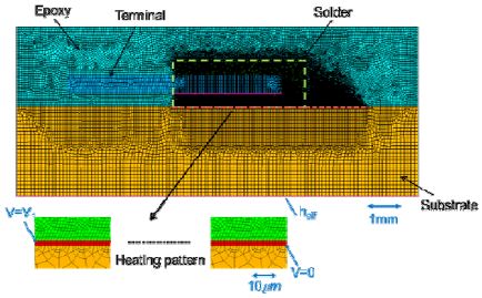
PPT의 열특성을 조사하기 위해 2-D FEA 전기-열 모델이 개발되었고, Figure 2는 그 구조를 보여주며, 모델링에는 상용 FEA 도구인 ANSYS Multiphysics[8][10]를 사용하였다. 해석은 정상상태 가정 하에 수행되었고, 18만여 개의 quadrilateral 전산요소가 사용되었다. Figure 2에서 보여주는 것처럼, 발열부 (heating pattern)는 solder 층과 substrate 사이에 위치한다.
FEA 전체 모델과 발열부 치수는 각각 15.8mm x 6.4mm, 7.56mm x 0.0034mm 이고, 모델에서 발열부 소재는 NiP(8%P), 기판 소재는 AlN, 단자대 소재는 copper 이다.
Figure 2 는 모델의 전기적 하중조건과 열적 경계조건을 도해하는데, heff 는 유효 열전달계수, V1 은 일정한 직류 전압 조건을 의미한다.
본 해석에서는 heff 는 3540W/m2-K, V1 은 3V로 설정 되었다. 3V 전압이 인가되는 PPT 에서 발열율을 고려한 에너지 평형식을 정립하여 heff 를 설정하고, FEA 모델에 대입하여 최초 계산을 수행하였다. 궁극적으로 substrate 하면의 평균온도가 공정상 목표온도인 110°C 로 수렴할 때까지 수치적 반복 계산을 수행하여 heff 는 3540W/m2-K 로 결정되었다. FEA 모델의 주요 수치적 조건은 Table 1에 요약 되어있다.
PPT 전기-열 모델이 전산모사하는 다중 물리현상의 과정은 다음과 같다. 발열부에(heating pattern) 직류 전압이 인가되어 전류가 흐르고, 옴 손실에 의해 발열이 되며, 열전도에 의해 확산되어, 종국에는 substrate 하면에서 외부로 소산된다.
3. 모델 검증
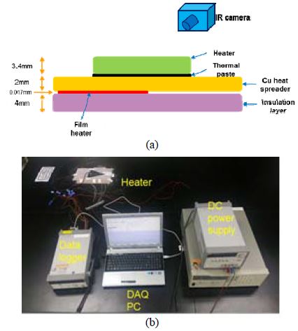
전기-열 모델의 검증목적용 히터 실험품과 측정리그가 구축되었으며, 히터 실험품 구조는 Figure 3 (a)에 측정리그는 Figure 3 (b)에 제시된다.
히터 실험품은 반지름 157mm 의 1/8 부채꼴 히터 플레이트로 Figure 1에서 보여주는 히터 플레이트의 1/8 크기이다. 실험품은 히터 플레이트, 히트 스프레더, 필름 히터, 단열층으로 구성된다. 필름 히터로는 127 x 127mm polyimide 히터가, 단열층으로는 에어로젤 단열재가 사용되었다.
측정리그를 구성하는 장비들은 열화상 카메라 (FLIR T440), 데이터 로거 (Agilent 34970A), DC 파워 서플라이 (Agilent 6655A, Agilent E3634A), DAQ PC 이다. 언급된 측정리그를 구성하는 장비 및 요소는 Table 2에 요약되어 제시된다.
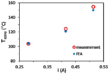
모델의 유효성을 검증하기 위하여, 파워 단자의 봉지재인 epoxy 표면온도 (Tepoxy) 에 대한 계산결과와 측정결과를 비교하였고, 온도 측정에는 열화상 카메라가 사용되었다. 측정 시 epoxy 표면의 열복사에 기인하는 측정 오류를 제어하기 위하여 표면을 흑색 코팅 물질로 도포하여 흑체에 유사하게 표면 처리를 하였으며, 열화상 이미지 획득 시 유효 방사율을 0.95로 설정하였다.
인가 전류에 대한 측정치와 계산치의 비교 결과는 Figure 4에 제시되어 있다. Figure 4에서 제시하는 결과에 의하면 측정치와 계산치의 최대차이가 약 3% 로 그 차이가 미미함이 확인되었으므로, FEA 전기-열모델은 해석 모델로 유효하게 활용될 수 있다.
4. 열특성
본 장에서는 PPT 의 열특성을 조사하기 위해, 전기-열모델을 활용하여 일정 전기-열 조건에서 (3VDC, 3540W/m2-K) 수행한 결과에 대해 논한다. 대표적 해석 결과로 PPT 의 전압장, 전류밀도장, 온도장이 제시된다. 이어서 PPT 의 열특성에 대한 봉지재 (encapsulant)의 열전도율, 기판 두께, 발열부 면적 영향에 대해 조사한 결과에 대해서 논한다.
4.1 전압장 및 전류밀도장
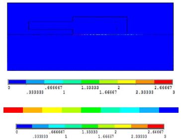
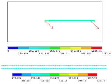
전압장과 전류밀도장 해석의 대표적인 결과가 Figure 5과– Figure 6에 제시되어 있으며, 전체 PPT와 발열부에서의 결과가 같이 나타나 있다. Figure 2에서 발열부에서 전기적 부하 조건을 참조하면 예상할 수 있듯이, 발열부를 제외한 다른 영역에선 절연상태임이 Figure 5에 잘 나타나 있다. 발열부에 형성되는 전류밀도의 크기와 방향은 Figure 6에 제시되어 있고, 평균적으로 529 A/mm2의 전류밀도가 형성됨을 알 수 있다.
4.2 온도장
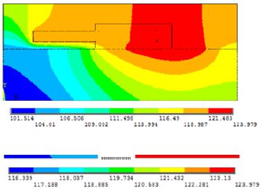
전체 PPT와 발열부에서의 온도장 해석의 대표 결과가 Figure 7에 제시되어 있다. 이 해석결과에서 발열부의 축방향 온도구배가 1 K/mm 로서 그 크기가 상당하고, 발열부가 substrate 하면보다 평균적으로 10°C 가 더 높음을 알 수 있다. 또한, PPT 각 층의 온도분포를 살펴보면 전기-열모델이 온도장 도출에 적합함을 정성적으로 확인할 수 있다.
4.3 매개변수 영향PPT 의 열특성에
PPT 의 열특성에 대한 봉지재 (encapsulant) 의 열전도율, 기판 두께, 발열부 면적 영향에 대한 연구 결과가 Figure 8 – Figure 10에 제시되었다.
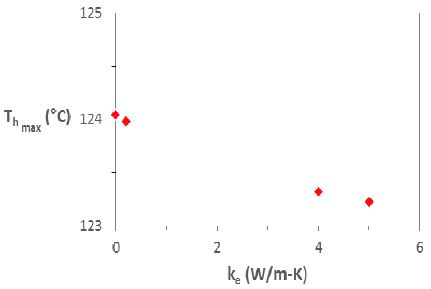
Effect of the thermal conductivity of the encapsulant on the maximum temperature of the heating element
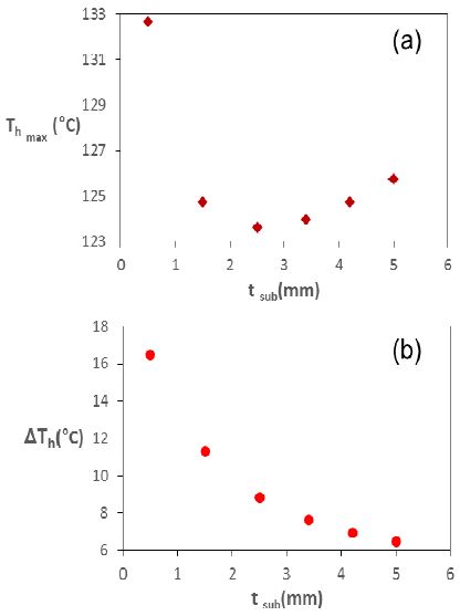
(a) The maximum temperature and (b) the axial temperature difference of the heating element as a function of substrate thickness
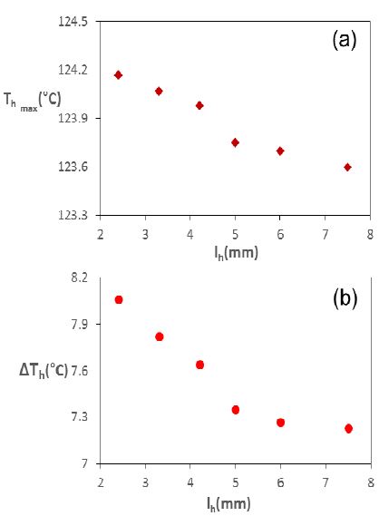
(a) The maximum temperature and (b) the axial temperature difference of the heating element as a function of heating element area
Figure 8에서 봉지재 열전도율이 0인 경우는 봉지재가 존재하지 않는 경우이며, 봉지재 열전도율이 4 또는 5W/m-K 인 경우는 에폭시와 실버 particle 의 복합 소재인 경우이고, 해석 결과 도출 시 기판의 두께는 3.4mm 로 일정하게 유지되었다. 열전도율이 0.2 W/m-K 에서 5W/m-K 로 25배 변화해도, 발열부 최대온도 (Thmax)는 124°C 에서 123.3°C로 겨우 0.6% 낮아지는 결과가 Figure 8에 나타나있는데, 이처럼 봉지재 열전도율이 발열부 최대온도에 미치는 영향이 미미한 것으로 확인되었다.
발열부의 최대온도와 축방향 온도차 (ΔTh)를 기판두께의 함수로 나타낸 결과가 Figure 9에 제시되어 있고, 해석 결과 도출 시 봉지재의 열전도율은 0.2W/m-K 로 일정하게 유지되었다.
주요 결과는 다음으로 요약할 수 있다. 0.5 ~ 5mm 기판두께에 대해서 발열부 최대온도의 최대치와 최저치는 각각 132.6°C, 123.5°C 로 7% 차이를 보이며, 축방향 온도차는 16.5°C 에서 6.4°C 로 61% 감소하여, 기판두께에 매우 종속적임을 알 수 있다. 또한 발열부 최대온도는 2.4mm 두께에서 가장 낮음이 확인되었다.
Figure 10 은 발열부의 최대온도와 축방향 온도차를 발열부 면적의 함수로 나타낸 해석결과를 제시한다. 발열부 면적이 3배 늘어날 때 최대온도가 124.2°C 에서 123.6°C 로 단지 0.5% 감소함을 보이는데, 이처럼 발열부 최대온도에 대한 발열부 면적영향은 미미하다. 반면, 발열부 면적이 3배 증가할 때 축방향온도차는 8.1°C 에서 7.3°C 로 10% 감소함을 보인다.
5. 결 론
본 연구에서는 반도체 제조용 히터 플레이트의 파워단자부의 열특성을 조사하기 위해, FEA 전기-열 모델을 개발하였고, 실험적으로 모델을 검증한 후, 파워단자부의 정량적 열특성과 매개변수 의존성을 수치적으로 조사하였다. 본 연구에서 주요 결과를 다음으로 요약하였다.
첫째, 파워단자부의 발열부에서 1 K/mm 의 상당한 온도 구배가 발생됨이 발견되었다. 둘째, 봉지재의 열전도율이 0.2 W/m-K 에서 5W/m-K 로 25배 증가해도 발열부 최대온도는 0.6% 감소함으로써 봉지재 열전도율의 영향은 미미한 것으로 확인되었다. 셋째, 0.5 ~ 5mm 범위의 기판두께에 대해서 발열부 최대온도의 최대치와 최저치는 7% 차이를 나타내며, 축방향 온도차는 61% 감소함이 발견되어 기판두께의 영향이 큰 것으로 조사되었다. 마지막으로, 발열부 면적이 3배 증가할 때 최대온도는 0.5% 감소하고, 축방향 온도차는 10% 감소하여, 기판두께에 비교하여 상대적으로 그 영향이 작음이 확인되었다.
Acknowledgments
이 논문은 부경대학교 자율창의학술연구비(2016년)에 의하여 연구되었음.
References
-
J. Lee, H. G. Kwon, S. Shin, S. Han, J. Ha, H. Yoo, and H. H. Cho, “Thermal design of hot plate for 300mm wafer heating in post-exposure bake”, Microelectronic Engineering, vol. 88, p3195-3198, (2011).
[https://doi.org/10.1016/j.mee.2011.08.012]

-
H. T. Chua, A. Tray, Y. Wang, and X. Wu, “A heater plate assisted bake/chill system for photoresist processing in photolithography”, Applied Thermal Engineering, vol. 29(no. 5-6), p985-997, (2009).
[https://doi.org/10.1016/j.applthermaleng.2008.05.024]

- J. Y. Song, C. K. Song, S. K. Roh, and H. Y. Park, “Reliability evaluation system of hot plate for photoresist baking”, Journal of the Korean Society of Precision Engineering, vol. 19(no. 8), p180-186, (2002).
-
C. D Schaper, M. M. Moslehi, K. C. Saraswat, and T. Kailath, “Modeling, identification, and control of rapid thermal processing systems”, Journal of The Electrochemical Society, vol. 141(no. 11), p3200-3209, (1994).
[https://doi.org/10.1149/1.2059302]

- T. K Lim, and S. H Rhi, “Experiment study on nanofludic heat pipe hot chuck in semiconductor wafer baking process”, Journal of Mechanical Science and Technology, vol. 24(no. 7), p1501-1509, (2010).
- W. K Ho, A. Tay, and C. D. Schaper, “Optimal predictive control with constraints for the processing of semiconductor wafers on bake plates”, IEEE Transactions on Semiconductor Manufacturing, vol. 13(no. 1), p88-96, (2000).
-
K. V. Ling, W. K. Ho, B. F. Wu, A. Lo, and H. Yan, “Multiplexed MPC for multizone thermal processing in semiconductor manufacturing”, IEEE Transactions on Control Systems Technology, vol. 18(no. 6), p1371-1380, (2010).
[https://doi.org/10.1109/tcst.2009.2036155]

- ANSYS Multiphysics User’s Guide, ANSYS Inc., (2016).
- M. N. Ozisik, Heat Conduction, New York, John Wiley and Sons Inc., (1993).
-
S. K. Yun, and S. S. You, “A study on the thermal analysis for the robotic arm of the cord blood storage tank”, Journal of the Korean Society of Marine Engineering, vol. 32(no. 5), p724-729, (2008), (in Korean).
[https://doi.org/10.5916/jkosme.2008.32.5.724]


