Study on torsional vibration characteristics of small high-speed marine diesel engine crankshaft system with viscous friction damper: Numerical calculation method of torsional angular displacement and stress using simultaneous measurement values at two points
Copyright © The Korean Society of Marine Engineering
This is an Open Access article distributed under the terms of the Creative Commons Attribution Non-Commercial License (http://creativecommons.org/licenses/by-nc/3.0), which permits unrestricted non-commercial use, distribution, and reproduction in any medium, provided the original work is properly cited.
Abstract
In this study, to reduce the torsional vibration force on a shafting, a two-points simultaneous measurement was performed for the damper inertia ring and damper casing parts of a high speed marine diesel engine crank shaft system with a viscous friction damper. The proposed method to directly measure the relative torsional angular displacement waveform of the damper inertial ring and casing parts is to simultaneously measure the dynamic torsional stiffness and damping coefficient. We used dynamic characteristics value obtained from measurements and performed numerical calculations (using the transfer matrix method) of the torsional vibration angular displacements and the torsional stresses of the viscous friction damper of the marine diesel engine crankshaft system.
Keywords:
Marine diesel engine, Viscous friction damper, Dynamic characteristics, Crankshaft system, Simultaneous measurement at two points, Transfer matrix method1. Introduction
The torsional vibration of small high-speed marine diesel engines has become more significant with the increase in exciting forces at high pressures. Therefore, the running engine crankshaft is highly stressed owing to the large torsional vibration [1]-[8]. Hugh-performance torsional viscous friction dampers have been employed in high mean effective pressure marine diesel engines for vibration reduction [9]-[14]. The dynamic characteristics of the dampers have a considerable influence on the vibration of the engine crankshaft system that cannot be ignored, and the viscosity of the silicone fluid and dimensions of the damper inertia ring have been varied in experiments [1]-[8]. To obtain measurements of the torsional vibration displacement, a phase-shaft type torsiograph equipment is used for the simultaneous measurement of the angular displacements of damper casing and inertia ring [1]-[5]. Both the dynamic torsional stiffness and damping coefficient of the dampers can be obtained from the harmonically analyzed results of waveforms measured at the damper casing and inertia ring [6]-[8]. In these experiments the 6-liter, 6-cylinder, and in-line high-speed marine diesel engine with well-known torsional vibration characteristics is regarded as a torsional vibration oscillator.
2. Main Specifications of Marine Diesel Engine and Viscous Friction Dampers
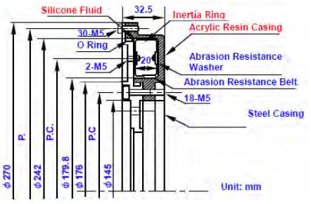
The test engine used for measurements of the torsional vibration angular displacement waveform is a 6-cylinder, in-line, marine or automotive high-speed diesel engine. The main specifications of the test engine are given in Table 1.The dimensions and the shape of the standard viscous friction damper, shown in Figure 1, were decided by considering widely used dampers in marine or automotive high-speed diesel engines. As seen in Table 2 (a), Table 2 (b), and Table 3, the dimensions of the viscous friction damper inertia rings and the viscosities of the silicone fluids, were varied to investigate the dynamic characteristics of the torsional stiffness and damping coefficient of the viscous friction dampers. The numbers assigned to the damper inertia rings of the standard viscous friction dampers (No. 02-S*) are given in Table 2 (a) and Table 2 (b). The dimensions of the gap of the standard damper were determined from the B.I.C.E.R.A. empirical formula [15]. The peripheral and lateral gaps between the damper inertia ring and the damper casing of the other dampers were changed based on the gap of the standard damper. Table 3 gives the values of the viscosities used in the experiments.

Dimensions of the Viscous Friction Damper Inertia Ring [Change in Lateral Gap, Peripheral Gap: Constant]

Dimensions of the Viscous Friction Damper Inertia Ring [Change in Peripheral Gap, Lateral Gap: Constant]
3. Torsional Angular Displacement Waveform Measured Simultaneously at Two Points
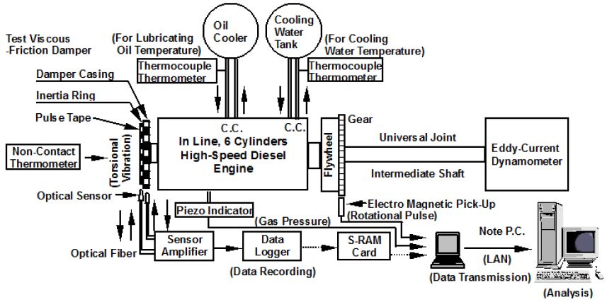
The test engine was equipped with a torsional viscous friction damper [1]-[5]. An eddy-current dynamometer was connected to the crankshaft of the engine via an intermediate shaft, a universal joint, and rubber coupling. The torsional vibration waveforms were simultaneously measured, at the periphery of the damper inertia ring and damper casing. Transparent acrylic resin suitable for penetrating light was used as the material of the damper casing part. The tapes, in which white and black parts were arranged alternately for generating signal pulses, were stuck on the periphery of the damper casing and damper inertia ring. The floodlight from the light emission division of the photo sensor and the reflected light were detected by a lightreceiver. The electric frequency signals proportional to the engine speed were obtained from the optical sensor. The measured signals were transmitted to the phase-shift type torsiograph equipment via the adapter which calculated the average of the angular velocity (the center frequency). The torsional vibration waveforms were obtained from the torsional angles, numerical calculated by the relationship between the measured and center frequencies. The signal was recorded by the data logger via the amplifier. The measured torsional waveforms of the damper inertia ring and damper casing were harmonically analyzed using a personal computer. The schematic of the experimental system is shown in Figure 2. The torsional vibration waveforms were measured under full load from 1000 to 3000 [r/min]. The temperature of the cooling water and lubricating fluid of the engine were kept constant, and the surface temperature of the viscous damper was retained at 333 [K] during the experiments.
4. Measurement Results of the Amplitude of the Torsional Angular Displacement
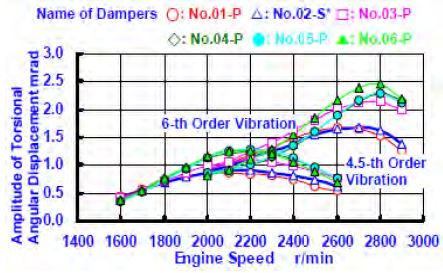
Figure 3 (a) and Figure 3 (b) illustrate the measured torsional amplitude curves with changing peripheral and lateral gaps and a kinematic viscosity of the silicone fluid is 0.10 [m2/s]. It can be inferred from the measured amplitude curves, that, the peripheral and lateral gaps are considerably influenced by the torsional vibration of the engine crankshaft system.
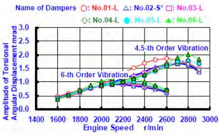
Amplitude Curves of the Torsional Angular Displacements at the Damper Casing for the Conditions with a Peripheral Gap Change [Lateral Gap: Constant, Kinematic Viscosity: 0.10 [m2/s], In-Line 6-Cylinder Engine]
5. Formula for Numerical Computation of Dynamic Characteristics Value in the Silicone Fluid Part of a Viscous Friction Damper
The viscous friction damper consisted of an annular seismic mass enclosed in a damper casing filled with silicone fluid. The values of the dynamic torsional stiffness and damping coefficient of the viscous friction parts were obtained from the harmonically analyzed results of the waveforms measured at the damper inertia ring and damper casing.
The equation of motion at the damper inertia ring is as follows:
| (1) |
Here,
| (2) |
Equation (3) and Equation (4) were obtained by rearranging Equation (1), into which the above-mentioned relational expressions (2) were substituted. The dynamic torsional stiffness and damping coefficient are given by,
| (3) |
| (4) |
where, θVFD,d and θVFD,p [rad] are the torsional angular displacements of the damper inertia ring and damper casing respectively, M = θVFD,d 0/θVFD,p0 is the amplitude ratio, IVFD is the inertia moment of the damper inertia ring [kgm2], is the complex damping coefficient of the silicone fluid [Nms/rad], , and ω is the circular frequency of the i-th order vibration [rad/s]. In Equation (3) and Equation (4), the values of the amplitude ratio M and phase angle between the damper inertia ring and damper casing φ can be obtained by harmonically analysing the waveforms measured at the damper inertia ring and damper casing. In addition, the values of IVFD and, ω are known. Therefore, the values of the dynamic torsional stiffness KVFD , and damping coefficient CVFD , can be determined from Equation (3) and Equation (4), respectively. [See Figure 4 (a) and Figure 4 (b)].
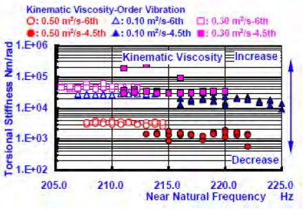
Relationship between Torsional Stiffness and Near-Natural Frequency by Simultaneous Measurement at Two Points [Inertia Ring Number: No. 04L, In-Line 6-Cylinder Marine Engine]
6. Dynamic Torsional Stiffness and Damping Coefficient of the Silicone Fluid in the Viscous Friction Damper
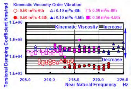
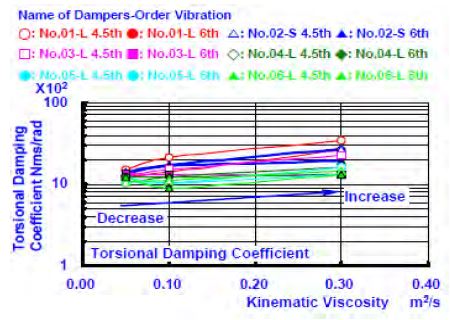
Figure 4 (a) and Figure 4 (b) show the dynamic torsional stiffness and the natural frequency obtained from the experimental results from the viscous damper, which was inserted into inertial ring No. 04-L in the damper casing in the engine. The natural frequency was obtained by sampling several points in the neighbourhood of the resonance frequency. As the viscosity of the filling silicone fluid increased, the values of the dynamic torsional stiffness constant of the 4.5-th and 6-th order vibrations increased. This is consistent with the previous study, and Figure 5 (a), Figure 5 (b), Figure 6 (a), and Figure 6 (b) show the changes in the torsional stiffness and torsional damping coefficient. The difference of the damping coefficient that generated the change in the viscosity of the filled silicone fluid from 0.05 to 0.10 [m2/s] was increased approximately ten times. However, the difference of the damping coefficient that generated the change in viscosity from 0.10 to 0.30 [m2/s], was only several percent. As for the reduction effects of the torsional oscillation resonance amplitude on the damper, the influence of the damping coefficient and torsional stiffness constant was large, and the reason for the increased viscosity of the silicone fluid (of low viscosity). Furthermore, as for the dynamic traits of the damper filled with a silicone fluid with higher viscosity, it should have been examined using only a damping coefficient. The experimental results showed that it is Study on torsional vibration characteristics of small high-speed marine diesel engine crankshaft system with viscous friction damper Journal of the Korean Society of Marine Engineering, Vol. 41, No. 8, 2017. 10 727 necessary to consider a damping coefficient with fixed torsional stiffness. The dynamic characteristics of the viscosity of the other viscous friction dampers showed a similar tendency.
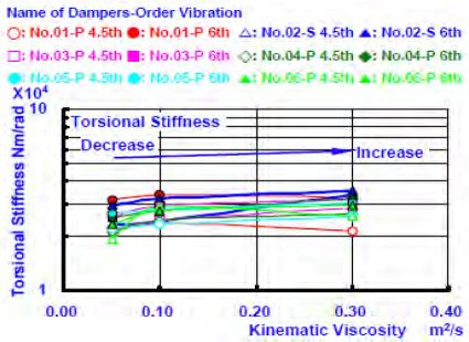
Relationship between Torsional Stiffness and Kinematic Viscosity with Conditions of Changing Peripheral Gap [Lateral Gap: Constant]
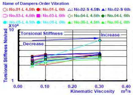
Relationship between Torsional Stiffness and Kinematic Viscosity with Conditions of Changing Lateral Gap [Peripheral Gap: Constant]
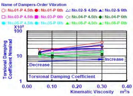
Relationship between Torsional Damping Coefficient and Kinematic Viscosity with Conditions of Changing Peripheral Gap [Lateral Gap: Constant]
7. Analysis of Forced Vibrations of Engine Crankshaft System with Viscous Friction Damper using Transfer Matrix Method
7.1 Vibration Model and Definition of State Vectors
The marine diesel engine crankshaft system with a torsional viscous friction damper consists broadly of a viscous friction damper, an engine, an intermediate shaft including a rubber coupling, a universal joint and an eddycurrent dynamometer. Figure 7 shows the details of the vibration model of the analyzed in-line, 6-cylinder engine crankshaft system. In this model the crankshaft system was assumed to be elastically supported by the main and thrust bearing of the crankshaft, and with bearings of the dynamometer. The external forces were assumed to apply concentrically to the crankpins in the tangential and nominal directions. In this model, it was assumed that the elastic supports of the bearings could be replaced with concentrated linear springs and dampers, and that the concentrated external forces apply to the center of the pins. As the engine crankshaft systems are very complicated, the crankshaft system was initially divided into many elements and the transfer matrices were determined for each element to define a mass-elastic system in three dimensional space. Axial, torsional, and two types of bending vibrations were considered at each divided element, and the state vector q at both ends of each element was defined as follows;
| (5) |
(T : Transposed vector)

Whole Vibration Model of a In-Line 6-Cylinder Marine Diesel Crankshaft System with a Viscous Friction Damper for Transfer Matrix Method
Here, u is the displacement in the x-axis direction [m], N is the force in the x-axis direction [N], θ is the torsional angular displacement [rad], T is the torsional moment [Nm], v is the displacement in the y-direction [m], ϕ is the angular displacement in the z-direction [rad], Mz is the moment in the z-direction [Nm], V is the shearing force in the y-direction [N], w is the displacement in the z-direction [m], φ is the angular displacement in the y-direction [rad], M is the moment in the y-direction [Nm], Q is the shearing force on the z-direction [N].
7.2 Transfer Equation and Numerical Computation Matrix Solution
From the vibration model of the engine crankshaft system with a viscous friction damper shown in Figure 7, the transfer equation connecting a state vector qVFD,L at the left-hand side of the engine and state vector qED,R at the right-hand side of the dynamometer can be represented by Equation (6).
| (6) |
Here, the transfer matrix of the viscous friction damper is
| (7) |
the transfer matrix of the engine is
| (8) |
the transfer matrix of intermediate shaft is
| (9) |
And the transfer matrix of dynamometer is
| (10) |
Here, the square transfer matrices are as follows: ZVFDI : inertia ring of viscous friction damper, ZVFDS : silicone fluid of viscous damper, ZVFDC : casing of viscous damper, ZFLY : Flywheel, ZJ ,R,1 , ZJ ,R,2 : right-hand side of crankshaft, ZK,7 : 7-th main bearing, ZPHE,5 : phase change between adjacent crank throws, Z6 : 6-th crank throw, Z5 : 5-th crank throw, Z4 : 4-th crank throw, ZL : thrust bearing, Z3 : 3-rd crank throw. Z2 : 2-nd crank throw, Z1 : 1-st crank throw, ZJ ,L,1 , ZJ ,L,2 : left-hand side of crankshaft, ZPUL : pulley, ZIS : intermediate shaft system, ZRC : rubber coupling and universal joint, ZPL : plate, ZEDJ ,L,1 , ZEDJ ,L,2 : left-hand side shaft element of eddy-current dynamometer, ZEDJ ,R,1 , ZEDJ ,R,2 : right-hand side shaft element of dynamometer, ZEDK ,1 , ZDEK ,2 : main bearing of dynamometer, ZED,R : rotor of dynamometer, and column state vector at qED,R : right-hand side of dynamometer, and qVFD,L : left-hand side of viscous damper. The boundary conditions at both the left and right-hand sides are free, and were applied to Equation (6). All forces and moments are zero and the displacement is an unknown. Therefore, the boundary matrix RL and the unknown displacement vector AL were introduced to derive the physical equations. The state vector at the left hand side of the crankshaft under the boundary conditions can be represented as :
Therefore, Equation (6) can be represented by Equation (11).
| (11) |
Assuming a free end at the right-hand side of the crankshaft system, boundary matrix RR is introduced to derive the physical quantities and pre-multiplied by state vector qED,R at the right-hand side of the crankshaft system, and
| (12) |
Therefore, from Equation (11).
| (13) |
by solving a set of complex linear equations, and unknown displacement AL at the left hand side of the crankshaft can be determined. The state vectors at each of the divided positions are obtained by successively pre-multiplying the obtained state vector qVFD,L at the left-hand side by transfer matrices. This numerical computation method can computer the vibration conditions per orders by using the amplitudes and phase angles of the harmonic exciting forces and phase angle of the firing order.
7.3 Superposition of Harmonic Vibration Frequencies
Using the numerical computation method presented in the previous section, the state vector per order of the vibration components was computed at arbitrary position of the engine crankshaft. There, the vibration stress and angular displacement waveform were superposed using the following equations.
| (14) |
| (15) |
Here, τt, k and θx,k are, the torsional vibration stress [Pa] and angular displacement amplitude of the k-th order vibration [rad], respectively, and φt,k are the corresponding phase angles [rad]. τt,0 and θx,0 are the respective initial values. As a four-stroke cycle engine was assumed in this work, the order of vibration components of the 0.5-th, 1-st, 1.5-th 2-nd dampers. etc. were considered in the computation. The torsional (shearing) stress of the k-th order vibration in Equation (14) and Equation (15) can be computed using Equation (16).
| (16) |
where, ZP is the torsional section modulus of the crankshaft at the position of observation [m3].
8. Numerical Computation Results of Torsional Vibration Angular Displacements and Vibration Stresses on a Crankshaft System with the Dynamic Characteristics Values obtained from the Simultaneous Measurement at Two Points
8.1 Numerical Calculation Results of the Torsional Vibration Angular Displacement
Figure 3 (a) and Figure 3 (b) show a comparison between the numerical calculated results (refers to Clause 4) and the measured results of the torsional vibration angular displacement of the crankshaft system with a viscous friction damper. However, a value obtained from the simultaneous measurement method at two points, was applied to the dynamic characteristics value (a dynamic torsional stiffness and damping coefficient) of the silicone fluid in the numerical calculations. The plots show the measurement results and the solid line represents the numerical calculation results. The numerical calculation results of the torsional vibration characteristics and the amplitude values were compared with the measurement results. These results showed the adequacy of the dynamic characteristics value of the silicone fluid provided by the simultaneous measurement method at two points.
8.2 Numerical Calculation Results of the Torsional Vibration Stresses
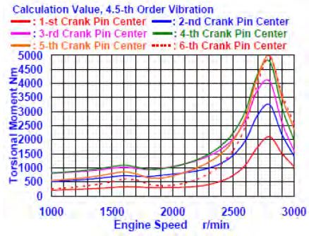
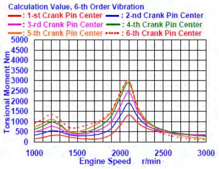
As an example of the numerical calculation results, Figure 8 and Figure 9 show the torsional vibration moment amplitude curves of the 4.5-th and 6-th order vibrations, which are in the center position of the crank pin of the test engine. The torsional vibration moment of the free end (a pulley end side) is the smallest, and this moment becomes larger, nearer to flywheel side. This is because the node of the vibration exists near the 6- th pin intermediate position on the vibrational mode of the crankshaft system. In addition, the torsional moment in the intermediate position of each crank pin on the resonant revolution has different characteristics. Furthermore, the torsional vibration angular displacement characteristics, torsional vibration stresses, and torsional vibration moments are coincident. In addition, the torsional vibration moment is given by Equation (17):
| (17) |
where, τ is the torsional vibration stress [Pa], T is the torsional moment [Nm], and Zt is the section modulus of the torsion. If the section modulus is constant, the torsional vibration stress and vibration moment have similar characteristics.
9. Conclusions
Simultaneous measurement at two points of the torsional vibration angular displacement of a damper inertia ring and damper casing was performed. In the engine experiment the attached viscous friction damper changed the side of the viscous damper. The viscosity of the gap in the peripheral and lateral directions also varied for the silicone filling fluid. From the results of measurement and the numerical calculations of the dynamic characteristics of the viscous friction dampers, we drew the following conclusions:
- (1) The comparison between the measured value and numerical calculation results of the torsional vibration angular displacement showed the adequacy of this numerical calculation method.
- (2) As the viscosity of the silicone fluid used to fill the viscous friction damper increased, the torsional stiffness and damping coefficient increased. The estimation of these dynamic characteristics is important in the design of viscous friction dampers.
- (3) The torsional vibration moment increased, near to the flywheel side. In addition, the torsional vibration angular displacement characteristics, torsional vibration stress and torsional vibration moment characteristics coincided.
References
-
T. Kodama, K. Wakabayashi, Y. Honda, and S. Iwamoto, “Dynamic characteristics of viscous-friction dampers by simultaneous vibration displacement measurement at two points”, SAE World Congress, SAE Technical Paper No. 2001-01-0281, p1-12, (2001).
[https://doi.org/10.4271/2001-01-0281]

-
T. Kodama, K. Wakabayashi, Y. Honda, and S. Iwamoto, “Three dimensional vibration characteristics of high speed automotive diesel engine crankshaft system with a viscous fluid damper”, SAE World Congress, SAE Technical Paper No. 2002-01-0165, p1-8, (2002).
[https://doi.org/10.4271/2002-01-0165]

- T. Kodama, K. Wakabayashi, Y. Honda, and S. Iwamoto, “An experimental study on dynamic characteristics of torsional stiffness and torsional damping coefficient of viscous-friction dampers”, Transactions of Kokushikan University, Faculty of Engineering, no. 35, p67-79, (2002).
- T. Kodama, K. Wakabayashi, Y. Honda, and S. Iwamoto, “An investigation on the three dimensional vibration characteristics of high-speed diesel engine crankshaft system with a viscous fluid damper”, Transactions of Kokushikan University, Faculty of Engineering, no. 36, p30-40, (2003).
- T. Kodama, K. Wakabayashi, Y. Honda, H. Okamura, and S. Iwamoto, “Dynamic characteristics of torsional stiffness and torsional damping coefficient of viscous-shear dampers by changing viscosity of silicone fluid and clearance between damper casing and damper inertia ring”, Proceedings of International Conference for Automotive Engineering, p255-266, (2003).
- T. Kodama, Y. Honda, and K. Wakabayashi, “Dynamic characteristics of viscous-shear dampers obtained by simultaneous vibration displacement measurement at two points”, The 15th Asia Pacific Automotive Engineering Conference, APAC 2009, Proceedings APAC-321, p1-11, (2009).
- T. Kodama, and Y. Honda, “Numerical calculation of torsional vibration stress for engine crankshaft system with viscous friction damper – Numerical calculation by using value of two-point simultaneous measurement -”, Bulletin of Science and Engineering Research Institute, Kokushikan University, no. 28, p11-23, (2015).
- T. Kodama, and Y. Honda, “A study on the torsional vibration characteristics of small high speed marine diesel engine crankshaft system with viscous friction damper, - Numerical calculation method of torsional angular displacement and stress by using simultaneous measurement value at two pints -”, International Symposium on Marine Engineering and Technology, ISMT 2016, GS1 Advanced Propulsion System I, GS1-02 (2016), p037.
- T. Kodama, K. Wakabayashi, Y. Honda, and S. Iwamoto, “An experimental study on the dynamic characteristics of torsional viscous-friction dampers, - Behaviors of damper casing and inertia ring and dynamic characteristics of damper-”, Japan Society of Mechanical Engineering, Annual Meeting, no. F941, p107-108, (2001), (in Japanese).
- T. Kodama, K. Wakabayashi, and Y. Honda, “An experimental study on the dynamic characteristics of torsional viscous-friction dampers for high-speed diesel engine, -Relationship between damper clearance and kinematic viscosity of silicone fluid-”, Japan Society of Mechanical Engineering, Dynamic and Design Conference 2001, no. 635, on CD-ROM p1-6, (2001), (in Japanese).
- K. Wakabayashi, T. Haraguchi, T. Kodama, Y. Honda, and S. Iwamoto, “An investigation into the dynamic characteristics of torsional viscous-friction dampers by simultaneous measurement at two points”, Proceedings of the 6th International Symposium on Marine Engineering, ISME2000-TS-00089, p569-576, (2000).
- T. Monma, Y. Honda, and T. Kodama, “Numerical calculation method of diesel engine crankshaft system with viscous friction damper using dynamic characteristics by the simultaneously measuring at two points”, Japan Society for Design Engineering, Spring Meeting, no. A09, p49-52, (2013), (in Japanese).
- T. Monma, T. Kodama, and Y. Honda, “Numerical calculation method of diesel engine crankshaft system with viscous friction damper by using dynamic characteristics by the simultaneously measuring at two points, - Numerical calculation of torsional angular displacement and vibration stress using dynamic property by the measurement-”, 2012-2013 JSAE Kant, International Conference of Automotive Technology for Young Engineers (ICATYE), no. C1-4 on CD-ROM, p1-4, (2013), (in Japanese).
- T. Monma, T. Kodama, and Y. Honda, “Numerical calculation method of diesel engine crankshaft system with viscous friction damper by using dynamic characteristics by the simultaneously measuring at two points,” 2013-2014 JSAE Kant, International Conference of Automotive Technology for Young Engineers (ICATYE), on CD-ROM p1-4, (2014), (in Japanese).
- B.I.C.E.R.A., “Handbook on Torsional Vibration”, The British Internal Combustion Engine Research Association, Cambridge University Press, p520-558, (1958).

