A study on object tracking using CAMSHIFT algorithm and fuzzy logic controller
Copyright ⓒ The Korean Society of Marine Engineering
This is an Open Access article distributed under the terms of the Creative Commons Attribution Non-Commercial License (http://creativecommons.org/licenses/by-nc/3.0), which permits unrestricted non-commercial use, distribution, and reproduction in any medium, provided the original work is properly cited.
Abstract
It is very important to detect exactly objects in object tracking systems such as safety and surveillance systems. In this paper, we introduced a method to track random objects using the OpenCV library and Visual C++ program. In random object tracking systems, we cannot calculate the exact distance and bias angle between the object and the system. To solve this problem, we used the center of the object image to build a fuzzy logic controller to control the system in order to determine the required position of the object image. Because this system uses an autofocus camera, the area of the object image also affected the bias angle between the target and the system. Thus, in our system, the center and area of the object image were used to build the fuzzy logic controller. To improve the quality of the object tracking system, the CAMSHIFT algorithm was used. With the CAMSHIFT algorithm, a target can be detected by isolating its color and following the tracking window in order to distinguish the target from the other objects, even though these objects have the same color as the target.
Keywords:
OpenCV, CAMSHIFT algorithm, Object tracking system, Fuzzy logic controller1. Introduction
Today, computer vision is applied in many useful fields such as the military, industrial products counters, and exploration. In the maritime or ocean field, mariners typically rely on complementary monitoring methods: radar and satellite-based aids. Although radar aids are relatively accurate at long distances, their capacity to detect small, unmanned, or nonmetallic craft that do not reflect radar waves is limited. With computer vision, we can acquire process, analyze, and understand digital images to extract information and detect the exact location of the nearby objects. In automated systems, image information can be used as sensor data to detect parameters of the target image and control object tracking systems. Thus, the performance of the object identification method will determine the accuracy of system.
Many methods are available to track an object. In this paper, the Open Source Computer Vision (OpenCV) library and Continuously Adaptive Mean Shift (CAMSHIFT) algorithm will be used because our system will be controlled using a Visual C++ program, which is easy to integrate into the OpenCV library. OpenCV is an open source computer vision and machine learning software library with more than 2500 optimized algorithms, including a comprehensive set of both classic and state-of-the-art computer vision and machine learning algorithms, according to [1].
An image processing method is introduced to track and follow a random object. The CAMSHIFT algorithm is used together with the OpenCV library and Visual C++ program to calculate an object's location; this location is usually calculated in a small image called the search window. When the search window is identified, the location of the object can only be found in this window. The effects of almost disturbances and noises are eliminated, which improves the stability of the tracking system. The purpose of this paper is to find and track objects at close range.
In our system, the Visual C++ program calculates the coordinates of the object image center and area. From the parameters, a fuzzy logic controller calculates the pulse-width modulation (PWM), which is generated by the circuit that controls the servo motor. The angle of the camera is then adjusted so that that the center of object's image is at the center line of the frame.
2. CAMSHIFT algorithm
CAMSHIFT is an algorithm for image color segmentation introduced by Gary Bradski in 1998. The algorithm exploits the MEAN SHIFT by changing the search window when the center of the target image and center of the search window converge. CAMSHIFT can handle dynamic distributions by readjusting the search window size for the next frame based on the zeroth moment of the current frame distribution. This allows the algorithm to anticipate object movement to quickly track the object in the next frame. CAMSHIFT works by tracking the hue of an object's color. The video frames were all converted into HSV space before individual analysis, according to [2]-[4].
For discrete 2D image probability distributions, the center of the object in the search window can be found with the following steps:
Find the zeroth moment (total pixels of object image)
| (1) |
where, I(x,y) is the area of the object’s image in the search window.
Find the first moment (sum of all pixel coordinates) for x and y
| (2) |
| (3) |
The object’s center is:
| (4) |
To ensure effective tracking in each of the frames, the search window was moved toward the center of the object image and the MEAN SHIFT was recomputed until the center of the object image and center of the search window converged. After that, the new search window size was computed based on the zeroth moment M00. The window was centered around the center and the computation of the next frame was started, according to [5].
3. Fuzzy logic controller
As discussed above, in a random object tracking system, we cannot calculate the exact bias angle between the object and the system. In fact, the center and area of the object image is relative calculated because of differences in camera quality and environmental light. To address these problems, the fuzzy logic controller was used [6][7].
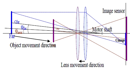
First, we determined the relationship between the image area and bias angle. As you know, with an autofocus camera, where the target is far to infinity, the distance from the lens to the image sensor is equal the focal length of the lens; when target moves toward camera, this distance increases. Based on that, from Figure 2, we have a conclusion: *increase of the same position of the object image center; if the object image area is small (the object is far the camera) the bias angle is large; if the object image area is large (the object is near the camera) the bias angle is small.
Hence, the bias angle not only depends on the position of object image center but also the area of the object image. Finally, the fuzzy logic controller was built with two inputs and a single output, according to [8]. The two inputs were the position of the object image center in the horizontal axis (x is from 0 to 640) and the percentage of the object image area over frame size (640 × 480). The single output is the change in PWM.
Subsets for Inputs and Output:
Input 1(x): position of the object image center in the horizontal axis
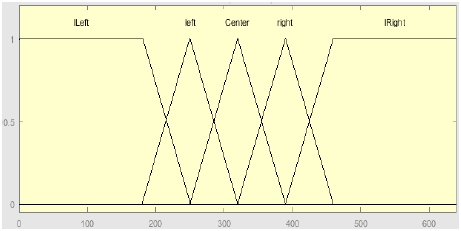
Membership Functions for input1: lLeft (large left), left, Center, right, lRight(large right)
Create membership function for input 1 with c.net code:
Input 1 has five membership functions; each function was created following one part of above c.net code. For example, the lLeft function equals one when x is from 0 to 180, when x is from 120 to 250, the lLeft function equals 250 minus x and over 70; and when x is greater than 250, the lLeft function equals 0. There is the same description for other membership functions.
Input 2(area): area of object image
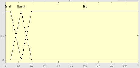
Membership Functions for input2: S (Small), N (Normal), B (Big)
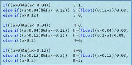
Create membership function for input 2 with c.net code:
Three membership functions of input 2 were created similar to input 1.
Output: the change of PWM
The fuzzy logic rule is shown in Table 1
In this system, the Min-Max rule was chosen. The operators had to be defined for fuzzy logic to represent logical connectives such as AND, OR, and NOT, demonstrated in [9].
| (5) |
| (6) |
| (7) |
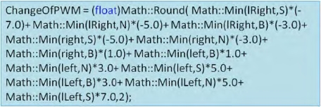
From the fuzzy logic rule and operators of fuzzy logic, the output was generated with c.net code:
When output was generated, this value was sent to PIC18f452 in the control circuit. A PWM signal was created by summing up the change in PWM and the current PWM value. The new PWM signal was sent to control the servo motor.
If the position of object image center is on the left, the change in PWM value will be negative, the PWM value will decrease, and the camera will be rotated to the left.
If the position of the object image center is on the right, the change in PWM value will be positive, the PWM value will increase, and the camera will be rotated to the right.
4. Random object tracking system and experiment result
4.1 Structure of system
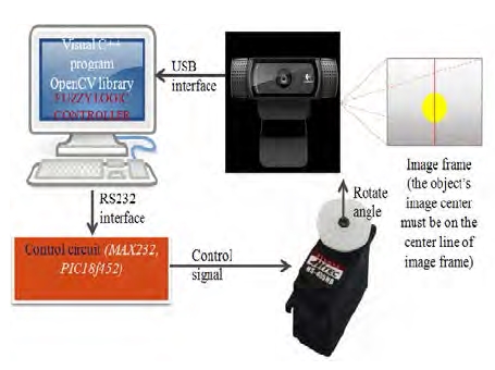
The random object tracking system is shown in Figure 5.
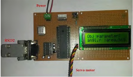
The system includes a Logitech HD Pro webcam; computer with Visual C++ program and OpenCV library; and control circuit with microprocessor PIC18f452 and Hitec HS-485HB servo motor. Once the center and area of the object image were calculated, a camera angle controlling system was designed with an HS-485 servo motor with operation angle of 900, traveling 900 μs one side and 1500 μs neutral, to obtain the above deviation.
4.2 Visual C++ program
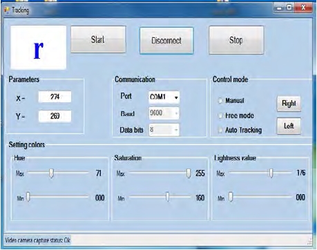
The program was created using the Windows Forms application for visual studio programs, according to [10]. Figure 7 shows the control window.
From the control window, we can select the available COM port in the computer to connect with the PIC, choose the control mode to control the system, and use color settings to better detect the target.
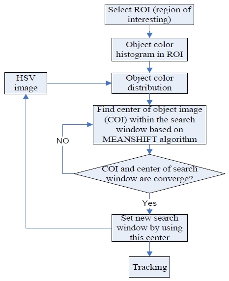
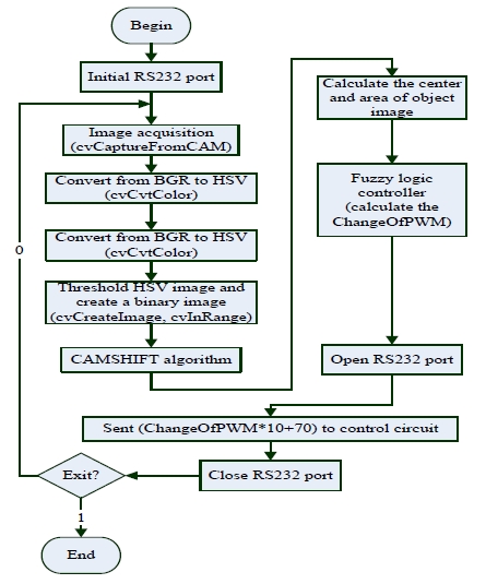
The flowchart in Figure 8 shows the basic steps of the program.
4.3 Experiment results
When the target is on the large-left side of the image frame (Figure 9(a)), the motor will be made to turn to the right side at a fast speed (indicated by character "R" in the control window). The speed of the motor will decrease (indicated by character "r" in the control window) when the target image position is near the central line of the image frame (Figure 9(b)). When the target is at the central line (Figure 9(c)), the motor will maintain this position (camera does not move, indicated by character "C" in the control window). The same control method was used when the target was on the right side of image frame (Figures 9(d) and Figures 9(e)). If we use the On-Off controller (motor speed is constant), an unstable state of the motor will occur around the center point.
5. Conclusion
The experimental results show that the system effectively performed in random object tracking.
By using the OpenCV library with the CAMSHIFT algorithm, the quality of object detection significantly improved. Using this method, the system tracked objects by combining the tracking window and object color in order to distinguish the main target among other same-colored objects.
When the fuzzy controller was applied to the object tracking system, the servo motor was controlled smoothly, exactly, and responded quickly.
References
- G. Bradski, and A. Kaehler, “Learning OpenCV computer vision with the OpenCV library”, O’Reilly, p1-29, (2008).
- R. J. Francois, “CAMSHIFT tracker design experiments with intel OpenCV and SAI”, IMSC-04-423, 2004 ARJF.
- Zhang, Y. Qiao, E. Fallon, and C. Xu, “An Improved CamShift Algorithm for Target Tracking in Video Surveillance”, Dublin Institute of Technology, 9th. IT&T Conference, (2009).
- P. Hidayatullah, and H. Konik, “CAMSHIFT Improvement on Multi-Hue and Multi-Object Tracking”, 2011 International Conference on Electrical Engineering and Informatics, 17-19 July 2011.
- A. Shalhi, and A. Y. Jammoussi, “Object tracking system using Camshift, Meanshift and Kalman filter”, World Academy of Science, Engineering and Technology, International Journal of Electrical, Computer, Energetic, Electronic and Communication Engineering, 64(4), (2012).
- Y. H. Lee, “Fuzzy-based tracking control of mobile robots”, Journal of the Korean Society of Marine Engineering, 34(1), p109-115, (2010), (in Korean).
- J. G. Ahn, “Fuzzy modeling for automatic steering design of a ship”, Journal of the Korean Society of Marine Engineering, 34(1), p102-108, (2010), (in Korean).
- C. Lee, “Fuzzy Logic in Control System: Fuzzy Logic Controller – Part 1”, IEEE Transactions on System, Man and Cybernetics, 20(2), (1990).
- R. Rojas, “Neural networks,” Springer-Verlag, Berlin, Chapter 11, “Fuzzy logic”, p289-310, (1996).
- “The OpenCV Reference Manual,” Release 2.4.9.0, p239-338, (2014).
