Mechanical property evaluation of functionally graded materials using two-scale modeling
Copyright ⓒ The Korean Society of Marine Engineering
This is an Open Access article distributed under the terms of the Creative Commons Attribution Non-Commercial License (http://creativecommons.org/licenses/by-nc/3.0), which permits unrestricted non-commercial use, distribution, and reproduction in any medium, provided the original work is properly cited.
Abstract
A functionally graded material (FGM) is a new type of advanced composite material that can be designed for use in thermal barrier coating and in heat shield applications owing to its high service performance that results from the improved mechanical and thermal properties of the material. An FGM is a nonhomogeneous material composed of various constituents and structures that gradually vary over the volume, and their mechanical properties vary smoothly from one surface to the other surface. The purpose of this study is to determine the effectiveness of two-scale modeling for FGM and to analyze its mechanical properties. Models of different volume fractions are developed with aluminum being used as the supporting matrix and silicon carbide being used as the particle inclusions. A geometry with three-point bending test is assumed. Through two-scale modeling, values representing the mechanical properties of the material are obtained at the macroscale level through a full model as well as at the microscale level through a representative volume element. The comparisons of the mechanical properties between macroscale and microscale. Therefore, the two-scale modeling presented herein is found to be useful and reliable for reducing numerical computational time. Based on the results, the stress value deviation becomes smaller as the volume fraction of the inclusion increases. In addition, the results provide evidence for the theory that an FGM has the advantage of smoother stress distributions.
Keywords:
Functionally graded material (FGM), Two-scale modeling, Mechanical behaviors1. Introduction
As technology progresses, becoming increasingly complex with greater performance demands, the need for advanced materials of improved performance capacities is increasing. This need appears in many fields, encouraging engineers to search for new materials. To meet these demands, composite materials that have many advantages in terms of strength, stiffness, toughness, and high temperature resistance have been developed.
A functionally graded material (FGM) is a modern composite material that can be designed for specific applications. An FGM is not a new material and in fact, there are naturally occurring FGMs. Bamboo, whose biological structure resembles that of composite materials, have been used in construction for a long time [1]. An FGM is a nonhomogeneous material that consists of various compositions and structures over volume and that has mechanical properties varying smoothly from one surface to another surface. For example, adhering a piece of metal to the upper part and a piece of ceramic to the lower part with a gradation phase located at the middle is more efficient for improving a performance of materials because both materials are able to preserve their individual properties while producing a continuous transition of mechanical characteristics across the three parts [2].
In traditional composites, the mechanical or thermal properties do not vary gradually. However, for FGMs, the presence of a gradation phase as a transitional phase, which is comprised of different constituents of various volume fractions and material properties, allow for a smooth and continuous transition in the mechanical properties. This continuous change, throughout the perpendicular axis of one side to other side, results in FGMs being superior than typical composite materials. Owing to the low or non-existence of drastic changes in material properties at any point, high stress concentrations are generally reduced. In addition, the presence of smooth transitional phases has the advantage of a smoother stress distribution within the material, which can influence the reduction in thermal and residual stress values.
Metal-ceramic FGMs, such as the Al-SiC based FGM, are able to withstand temperatures of 2000 K and able to avoid problems that originate from mismatches in the thermal properties [3][4]. Al-SiC FGMs can also be used in sub-marine applications such as in scuba diving cylinders [5]. For future applications, materials can be developed that combine FGM and carbon nanotube technologies.
The effective thermal conductivities of an FGM were obtained through numerical calculation using a finite element method [6]. Shen [7] investigated the static and dynamic torsional behaviors of FGMs using a nonlocal strain gradient theory. FGMs consisting of Al/SiC showed an enhancement in hardness and wear resistance from the core to the surface [8].
As FGM use increases, it is becoming necessary to understand the mechanical behavior of FGMs to maintain safe operating conditions. Chi [9] investigated the mechanical characteristics using a constant value for the Poisson’s ratio and continuous values for the elastic modulus. This depends on the volume fraction of the particle inclusions, which is determined by an exponential, power-law, or sigmoid function under a transverse load in an FGM specimen. In another study [10], it was shown that changing the Poisson’s ratio had a very small influence on the finite element analysis results.
In this study, we have suggested a two-scale modeling approach to be used in the numerical analysis of FGMs. The purposes of this study were to determine the effectiveness of two-scale modeling as well as to analyze the mechanical properties of FGMs. The study was carried out using commercial finite element code. The FGM studied herein consisted of an aluminum (Al) matrix with silicon carbide (SiC) as the particle inclusions, which was gradually distributed in the matrix. A simple three-point bending test was assumed. Through two-scale modeling, the mechanical behaviors were obtained at the macroscale using a full model as well as at the microscale using a representative volume element (RVE). Exchange information process between the both scales was present, which means that the values from the full model were localized to the RVE model and then, after some analyses, homogenized to the full model. The comparisons between both scales show satisfactory results. Thus, the two-scale modeling method suggested herein is found to be reliable and useful for reducing numerical computational times. The results provide evidence for the theory that FGMs have the advantage of smoother stress distributions. In addition, we have also shown a good agreement between the FEM models and theoretical equations with respect to the elastic modulus, bending stress, and strain values under bending conditions.
2. Modeling of FGM
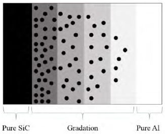
For this study, we used aluminum (Al) as the matrix and silicon carbide (SiC) as the inclusion particle for the FGM. Table 1 provides the modulus of elasticity and Poisson’s ratio for Al and SiC. In general, the gradation or transitional phase is located toward the in between of Al and SiC of the FGM body. The FGM gradation from metal to ceramic with material volume fractions in the ceramic material structure is shown in Figure 1.
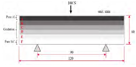
To perform a numerical analysis of the proposed FGM, a composite FGM was bounded by the metal at the upper part and the ceramic at the lower part. For the transitional phase, a material gradient of varying volume fractions is placed between the two boundaries, as shown in Figure 2 and detailed in Table 2. The presence of a gradation phase results in an excellent FGM relative to typical composites because there is a smooth change in material properties at the gradation phase that will reduce a large stress concentration within the material.
For the finite element analysis, which we performed using the commercial software Abaqus [12], a static two-dimensional analysis was chosen for modeling the composition and structure of the FGM. Then we assumed to make partition within the material layer by layer with different volume fraction of ceramic gradually and each layer is estimated as solid and homogenous for section assignment through Abaqus program. Besides that, we also consider a static modeling in the simulation. Because the material consisted of different inclusions from one layer to another, different elastic moduli existed for each layer. An effective elastic modulus was required, which is discussed in the next section.
To determine the mechanical properties of the FGM, we applied a three-point bending condition for the modeling, as shown in Figure 2. For a bending test, we made the overall structure of the material to resemble a rectangular beam with a length of 120 mm and a width of 60 mm. The lower supports are spaced 90 mm apart with a concentrated load of 100 N applied at the upper part, as shown in Figure 2. After modeling and performing some computations, we acquired certain mechanical properties of the overall FGM structure such as von Mises stress, maximum principal strain, and bending stress with respect to the center of the beam.
3. Methodology
3.1 Two-scales Modeling
Determining the mechanical properties of composite materials through computational analyses requires long computational times, often resulting in higher costs. Two-scale modeling is a process that aims to overcome these issues by combining macroscale and microscale analyses within one process calculation to reduce the large computational times. Regarding FGM structures, which have different inclusion volume fractions from one side to the other, we assumed different layers depending on the volume fraction of ceramic. At each layer, especially at the gradation phase layers, the macroscale mechanical properties are transferred and localized to the microscale level. Then, the property values are sent back and compared to the macroscale values to obtain to validate and update results through the homogenized on stress and stiffness.
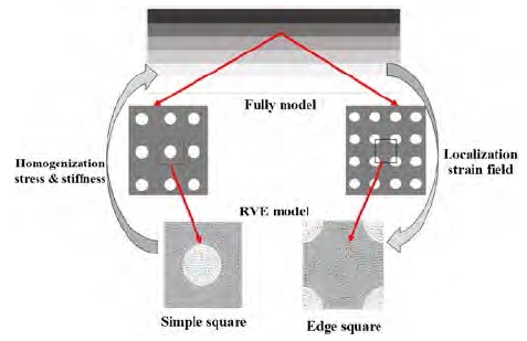
The macroscale calculation is carried out by the full model, while the microscale calculation is carried out by the RVE model. Meshing in the full model is coarser than in the microscale RVE model, resulting in the RVE model being more accurate. The two-scale modeling approach exhibits an exchange of information between the two scales, as depicted in Figure 3.
The full model, which was fully meshed, was employed to determine the mechanical properties at the macroscale level. The number of nodes and elements for the macroscale model are given in Table 3. To transfer the mechanical properties from the full model to the microscale RVE model, we considered a localization strain field calculation and adopted periodic boundary conditions (PBCs) as the limits of the RVE model. This relation is given by Equation (1)[13] as follows:
| (1) |
where u is the microscale displacement value. The + and – exponents indicate opposite edges of the RVE. Then is the average strain value at point (i, j). The displacement values from the full model were transferred to the RVE model as PBCs owing to the microstructure boundaries. Equation (2) shows the transformational displacement values from macroscale to microscale for two-dimensional modeling. εij represents the macroscale strains at node (i,j), and L1 and L2 are the edge lengths of the RVE in the x and y directions, respectively [13].
| (2) |
Here, the RVE is defined as the smallest volume of material that can represent the material as a whole. It should consist of effective properties and sufficient information, whose size is small enough than macroscale but large enough than microscale. The RVE for the simulation presented herein, which employs aluminum as a matrix and silicon carbide as a particle, avoided the interface, interactions, inclusions shape, and contact between the matrix and particle. With the displacement values set as PBCs, the stress or strain average values were calculated as per Equation (3) and are sent back to the macroscale level in order to update the stress or strain at each element for the full model. Because every node at the macroscale level has different displacement values, a symmetrical perception cannot be applied when substituting the PBCs. In addition, the displacement values from the full model were substituted as PBCs at each edge node and element of the RVE.
| (3) |
is averaging the average stress tensor over the volume of the RVE, v denotes the volume region of the RVE and σij is the actual stress tensor of the RVE.
3.2 Bending condition
The FGM specimen for the analysis herein was oriented to resemble a rectangular beam placed under simple three-point bending. From this, we determined the mechanical properties of the material with respect to the shape of a beam. The effective elastic modulus Eeff is used by many researchers for FGM evaluation. In this paper, we used the formula for advanced composite materials given by Upadhyay et al. [14], which is shown in Equation (4).
| (4) |
| (5) |
E1: Elastic modulus of ceramic
E2: Elastic modulus of metal
v1: Volume fraction of ceramic
v2: Volume fraction of metal
K is a constant given as:
| (6) |
| (7) |
Determining the x value from Equation (7) allowed us to obtain K by substituting the L, M, and N constants with the values shown in Table 4 for those of the Al-SiC composite materials. L, M, and N are constants that vary depending on the type of the composite materials. The details are available in [14]. Taking into account the K value, we can generate an effective elastic modulus for FGMs that consists of different ceramic inclusions.
Additionally, and for comparison purposes, we adopted the theoretical equation proposed by Tamura (TTO model) to determine Eeff. This approach has been adopted by many researchers for FGM studies [15]. The TTO model assumes a parameter q that reflects the ratio of the stress to strain transfer to determine the elastic-plastic behavior of the two-constituents ceramic-metal composite material. This is given by Equation (8) and (9),
| (8) |
| (9) |
where, σi and εi are, respectively, the average stress and strain of the constituents and νi is the volume fraction.
A bending moment exists for each bending condition. Therefore, in order to evaluate mechanical behaviors, flexural formulas were used to calculate the bending stress and strain. These are given in Equation (10), (11), and (12).
| (10) |
| (11) |
| (12) |
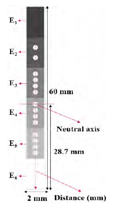
The transformed-section area is shown in Figure 4. Due to the presence of a neutral axis, y as a longitudinal point located at some distance above the neutral axis and I as the moment inertia, the bending stress and strain can be calculated. To evaluate the mechanical behavior, a distance path at the center of section that includes all different volume fractions was chosen.
4. Result and Discussion
This study examined and compared the results of a macroscale and microscale evaluation of an FGM composite material to determine the validity and the accuracy of a two-scale modeling approach. With regard to three-point bending, we compared the results from theoretical equations with the results from a numerical analysis performed using the software Abaqus to determine the accuracy of the mechanical behaviors within the model. The results were obtained through the thickness of material. At the macroscale level for the full model, which included a meshing process as part of the numerical analysis, we estimated mechanical properties such as von Mises stress, bending stress, and strain values. The von Mises stress was obtained as failure-state stress values. The bending stress was compared to the theoretical results. The strain values, which provide the intensity of deformation, were calculated.
As can be seen in Figure 5, the von Mises stress, which were determined along the thickness direction through the center of the specimen, decrease for different SiC volume fractions in the material. A high stress value occurred at the initial distance at the pure metal part due to an existence of concentrated load at that location. Meanwhile, at the gradation parts, which consists of different volume fraction of inclusions, the stress values are continuously decreasing and are in good agreement with the characteristics of FGM. The gradation parts therefore exhibit smoother stress distributions, which can improve the strength, stiffness, and toughness of advanced composite materials.
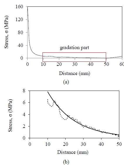
The variation of von Mises stress with respect to the distance measured from the neutral axis for (a) general distribution and (b) gradation part distribution
As with the bending stress values, the stress deviation decreases as the inclusion ratio increases resulting in a smoother bending stress distribution, as shown in Figure 6. Moreover, the strain values also exhibit similar distribution patterns, as shown in Figure 7. The strain values decrease smoothly at the gradation parts. The fluctuations indicate that the stress decreases while passing through the SiC particles and increases when passing through the matrix.
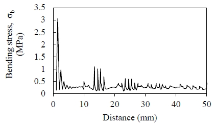
The variation of bending stress with respect to the distance from the neutral axis for the full model at the gradation parts
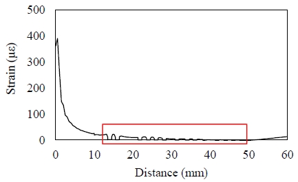
The variation of bending strain with respect to the distance from the neutral axis for the full model
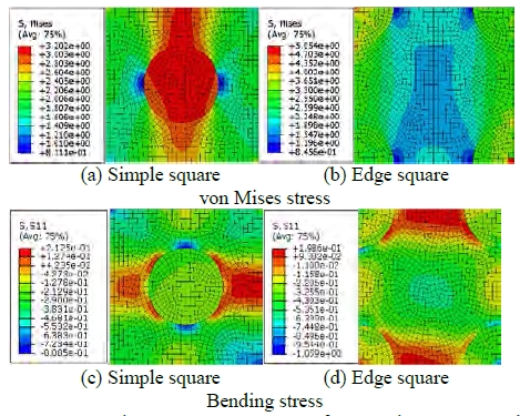
For the microscale results, we used two types of RVE shapes (Figure 8); the simple square RVE, which includes one spherical particle surrounded by the matrix, and the edge square RVE, in which the particles are divided into four parts located at the edge of the square. To determine the microscale mechanical properties, distance pathing was chosen to run through the center part of simple square RVE and through the left side of the edge square RVE.
To demonstrate the RVE model, the microstructure contours of the von Mises stress and bending stress are shown Figure 8. As seen, for the von Mises stress, the higher stress values occurred at the particle region whereas the lower stress values occurred at the matrix region. For the bending stress, on the other hand, the higher stress occurred at the matrix located around the particle region.
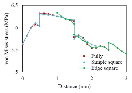
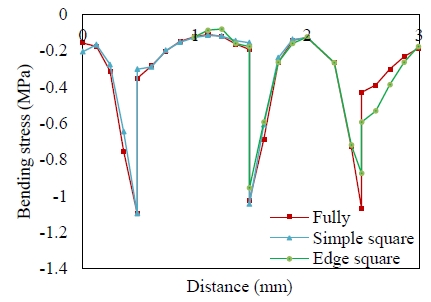
Then to determine the validity of the results, the comparison between both scales of von Mises stress and bending stress are shown, respectively, in Figure 9 and Figure 10. The example presented is for a 0.2 volume fraction of SiC inclusion with the remaining volume fraction being similar. We only evaluated the gradation parts of SiC inclusion volume fractions vf = 0.2, 0.4, 0.6, and 0.7. This was done because of the greater advantage of its behavior and the smoother distribution of stress value. Based on the results of the two-scale modeling approach presented herein, we estimate that this method is reliable, effective, and useful for reducing, to some extent, the long times required in computational analysis.
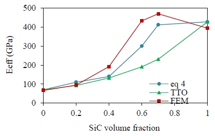
In order to determine the accuracy of the results, a comparison between the finite element code and theory was performed. As an advanced composite material, an FGM consists of an Eeff that takes into account the influence of the material properties [14]-[16]. Therefore, acquiring Eeff, the volume fraction and the elastic modulus of each constituent phase is necessary. The theoretical Eeff found through Equation (4) ~ Equation (7) matches that of the finite element method to a satisfactory degree. On the other hand, the TTO model with a q average of 99.3 GPa shows lower elastic moduli results for vf = 0.6 and 0.7 of SiC inclusions. However, the TTO model exhibited close results for vf = 0.2 and 0.4. When SiC was added to the Al metal constituent, which has different binding properties, it seemed to cause a heterogeneous interface and elastic modulus distortion. The lower results of Eeff may result from the fact that the interface between the constituents was ignored. Figure 11 shows the comparison of Eeff from the theoretical equations and from finite element analysis. The detailed values can be seen in Table 5. Overall, these Eeff estimations seem to be in a good agreement.
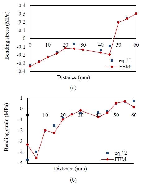
We used the effective elastic modulus above in the bending stress and bending strain equations shown in Equation (11) and Equation (12), for a neutral axis taken to be at 28.7 mm. The results match closely with those of the finite element method, as shown in Figure 12. Although both values exhibit good agreement with each other, it seems that there is a need to further improve the analytical calculation. From this, either the bending stress or bending strain would show a better result in tension and compression.
5. Conclusion
This study shows the suitability of a two-scale modeling approach as an alternative method for reducing the long times required in the computational analysis of certain mechanical properties of FGMs. The macroscale results from a fully meshed model were compared to the microscale results from an RVE model. The results exhibited satisfactory similarity. Because the stress deviation decreased as the inclusion ratio increased, a smoother stress distribution occurred in the gradation parts. To obtain accurate and reliable mechanical properties at the gradation parts, the RVE model was used and presented in detail.
In addition, the results from the theoretical calculation and those from the numerical analysis were compared to each other for determining the validity of the mechanical properties. It is clearly seen that different effective elastic moduli exist depending on the volume fraction. Using two types of theoretical equations showed a good agreement when FEM results compared with theoretical results. Both the bending stress and bending strain calculated from the theoretical equations and determined from the FEM model also exhibited meaningful and acceptable results.
Acknowledgments
This research was supported by the Basic Science Research Program through the National Research Foundation of Korea (NRF) funded by the Ministry of Education under grant number 2016R1D1AB03932125.
References
-
E. C. N. Silva, M. C. Walters, and G. H. Paulino, “Modeling bamboo as a functionally graded material: Lessons for the analysis of affordable materials”, Material Science, 41, p6991-7004, (2006).
[https://doi.org/10.1007/s10853-006-0232-3]

- T. Gürol, Finite Element Modeling of Beams with Functionally Graded Materials, M.S. Theses, Department of Civil Engineering, Middle East Technical University, Turkey, (2014).
- M. S. El-Wazery, and A. R. El-Desouky, “A review on functionally graded ceramic-metal materials”, Material Environment Science, 6(5), p1369-1376, (2015).
-
G. Udupa, and S. Rao, K. Ganggadharan, “Functionally graded composite materials: An overview”, Material Science Engineering, 5, p1291-1299, (2014).
[https://doi.org/10.1016/j.mspro.2014.07.442]

- G. Udupa, S. Shrikantha, and K. V. Gangdharan, “Future applications of Carbon Nanotube Reinforced Functionally Graded Composite Material”, IEEE-International Conference On Advances In Engineering, Science And Management, p399-404, (2012).
-
J. Turant, “Modeling and numerical evaluation of effective thermal conductivities of fiber functionally graded materials”, Computational Structure, 159, p240-245, (2017).
[https://doi.org/10.1016/j.compstruct.2016.09.068]

- Y. Shen, Y. Chen, and L. Li, “Torsion of a functionally graded material”, International Journal Engineering Science, 109, p14-28, (2016).
- T. Prabhu, “Processing and properties evaluation of functionally continuous graded 7075 Al alloy/SiC composites”, Archives Civil Mechanic Engineering, 17(1), p20-31, (2017).
-
S. H. Chi, and Y. L. Chung, “Mechanical behavior of functionally graded material plates under transverse loadpart I: Analysis”, Solid Structure, 43(13), p3657-3674, (2006).
[https://doi.org/10.1016/j.ijsolstr.2005.04.011]

-
S. H. Chi, and Y. L. Chung, “Mechanical behavior of functionally graded material plates under transverse loadpart II: Numerical results”, Solid Structure, 43(13), p3675-3691, (2006).
[https://doi.org/10.1016/j.ijsolstr.2005.04.010]

-
J. Goupee, and S. S. Vel, “Transient multiscale thermoelastic analysis of functionally graded materials”, Composite Structures, 92(6), p1372-1390, (2010).
[https://doi.org/10.1016/j.compstruct.2009.10.041]

- Abaqus User’s Manual, Dassault Systèmes Simulia Corp, Providence, RI. Version 6.14 edition, (2014).
- P. Meyer, and A. M. Waas, “Mesh-objective two-scale finite element analysis of damage and failure in ceramic matrix composites”, Integrating Materials and Manufacturing Innovation, 4(5), p1-18, (2015).
-
A. Upadhyay, and R. Singh, “Prediction of effective elastic modulus of biphasic composite materials”, Modern Mechanical Engineering, 2(1), p6-13, (2012).
[https://doi.org/10.4236/mme.2012.21002]

-
Z. H. Jin, F. H. Paulino, and R. H. Dodds Jr., “Cohesive fracture modeling of elastic-plastic crack growth in functionally graded materials”, Engineering Fracture Mechanics, 70(14), p1885-1912, (2003).
[https://doi.org/10.1016/s0013-7944(03)00130-9]

-
M. Bhattacharyya, S. Kapuria, and A. N. Kumar, “On the stress to strain transfer ration and elastic deflection behavior for Al/SiC functionally graded material”, Mechanics of Advance Materials and Structures, 14(4), p295-302, (2007).
[https://doi.org/10.1080/15376490600817917]


