Performance characteristics under various load conditions of coastal ship with LNG-powered system
Copyright ⓒ The Korean Society of Marine Engineering
This is an Open Access article distributed under the terms of the Creative Commons Attribution Non-Commercial License (http://creativecommons.org/licenses/by-nc/3.0), which permits unrestricted non-commercial use, distribution, and reproduction in any medium, provided the original work is properly cited.
Abstract
The use of dual fuel (fuel oil and LNG) propulsion on seagoing ships is becoming increasingly common. Although LNG is not only solution, it can be regarded as the most competent solution that complies with emission rules in practical terms among gaseous fuels such as methanol, and ethane. Having a very low or no sulphur content, sulphur oxides in the exhaust gas are negligible. The limited space and frequent ship loading in small LNG-fueled ships make it difficult for satisfactory ship operation or management. In addition, ships operating in coastal channels rarely continuously navigate under the condition of a steady-speed in comparison to oceangoing vessels. Thus, crews in gas-fueled ships find it problematic to recognize the key elements to be taken into account such as the LNG fuel consumption during frequent engine power variations, accurate remains of LNG fuel, next bunkering time, and prediction of possible navigation time and distance. The LNG bunker for these ships is generally provided by a tank lorry at a specific terminal or bunkering shuttle. Therefore, it is necessary to estimate the appropriate bunkering time for stable operation if the bunkering facility is insufficient and the system has fluctuating load conditions for the fuel gas supply.
This study assessed the system stability, LNG fuel consumption, and dynamic response of the gas supply system under voyage conditions such as emergency operations for sudden load variation and maximum navigation distance without LNG bunkering.
Keywords:
Small LNG fueled ship, Dual fuel propulsion, Coastal channel, LNG bunker, Emergency operation1. Introduction
Currently, oil-fueled two-stroke diesel engines are directly coupled to a propeller shaft in standard marine engines because of their high thermal efficiency of more than 50% when utilizing heavy fuel oil (HFO) or marine diesel oil (MDO). These engines use the following diesel process to produce power: high-pressure oil is injected into cylinders filled with highly pressurized air for combustion, and the explosive power is transmitted via a piston and crank mechanism to the propeller shaft. The main emission products from vessels are CO2, NOx, SOx, and particulate matter (PM). The emission products can increase the atmospheric temperature and air pollution and have various detrimental effects on the life forms on earth.
According to the Second IMO green house gas (GHG) report by IMO’s Maritime Safety Committee (MSC, 2009)[1], emissions are projected to increase in the future owing to globalization and growing energy demands. LNG as a ship propulsion fuel can decrease these emissions and satisfy the regulation demands [2][3].
To be effective, a dual fuel engine should maintain stable combustion of the gaseous fuel under various operating conditions. In contrast to a fuel oil (HFO or MDO), natural gas (mainly methane gas) does not ignite by itself when injected into a cylinder. For this reason, a fuel oil called the pilot oil is used for ignition regardless of the load. Thus, a DF engine must have a stable operation even under the following conditions:
- bunker change from one fuel to another,
- sudden load transients, and
- minimum load conditions during gas combustion.
LNG, in comparison to HFO as a ship fuel, produces a much cleaner exhaust that complies with the emission regulations of the IMO for gas engines over a broad range of power output [4]. Engine models include gas-only engines and DF four- and two-stroke engines. Methane slip is still significant in terms of GHG emissions from low-pressure injection systems; however, the study of the response time and stability of the engine load can proceed without considering its effect [5].
For small LNG-fueled propulsion ships such as the “Econuri”, the first LNG-powered vessel of Asia, the limited fuel tank size and frequent variation in engine power make it difficult to achieve a satisfactory level of ship operation. Moreover, vessels navigating in coastal channels rarely have continuous operations under a steady-speed compared to oceangoing vessels. Therefore, with regard to LNG bunkering, the crews of the ship find it difficult to recognize the key elements that must be considered such as the LNG fuel consumption during frequent engine power variation, exact remains of the LNG fuel, next bunkering time, and prediction of possible navigation time and distance [6]. The LNG bunker for these ships is provided from a tanker truck at a specific station or bunkering shuttle [7][8]. Thus, considerable efforts have been made by the suppliers, particularly in Korea, where the LNG bunkering infrastructure is very poor [9]. Generally, it is necessary to estimate the appropriate bunkering time for stable operation if the insufficient bunkering facility is insufficient and the system has fluctuating load conditions for the fuel gas supply.
In this study, we examined the system stability, LNG fuel consumption, and dynamic performance of the fuel gas supply system (FGSS) under voyage conditions such as emergency operations. The maximum fuel remaining in the fuel tank was determined for the next scheduled LNG bunkering. To analyze the dynamic performance, the Econuri ship of the Incheon Port Authority in Korea was chosen. This is the first LNG-fueled ship in Asia equipped with a low-pressure type, DFDE (dual fuel diesel engine), and LNG fuel tank of IMO type-C [10].
For the simulations, the main operating conditions for setting the initial start-up, normal load, and emergency were as follows:
(a) Conditions for initial start-up and normal load
- The initial tank level was set as 95% [10] and the pressure of the LNG fuel tank was 6.5 barg.
- The master gas valve was open.
(b) Emergency conditions
- The master gas valve was suddenly closed.
- The gas engine was isolated from the gas network.
2. Components of LNG Fuel Gas Supply System
2.1 Low-Pressure and High-Pressure Gas Fuel Engines
A low-pressure gas fuel engine is normally used in four-stroke, trunk piston-type engines [11]. The gaseous fuel is injected at a low pressure of approximately 5 barg during the intake stroke of the engine. Once the suction into the cylinder is complete under an air-mixed condition, ignition and combustion of the gaseous fuel is achieved after the pilot oil is injected and ignite at the final stage of the compression stroke. The pilot fuel oil consists of commonly used MDOs. Generally, a low-pressure DF engine is applied as the power-generating engine [12].
A high-pressure gas fuel engine is generally used in two-stroke, low-speed, crosshead-type engines, unlike the four-stroke DF engine in shich the gas is introduced to the gas injection valve. The gas pressure is increased between 250–300 barg using a high-pressure gas compressor. Usually, a high-pressure DF engine is used as a direct-coupling type of propulsion engine.
2.2 Fuel Gas Supply System
The FGSS for DF engines is classified into two types: a low-pressure type for four-stroke engines and a high-pressure type for two-stroke engines [13].
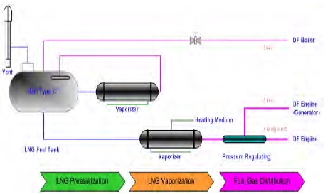
The low-pressure LNG fuel system for DF engines considered in this study mainly consisted of a fuel tank, pressure build up (PBU), vaporizer, main gas heater, gas valve unit (GVU), bunkering station, and engines connected by valves and pipes [14]. Figure 1 shows the schematic diagram of a low-pressure FGSS. LNG fuel was gasified if required, and then heated before entering the GVU, that has certain inlet requirements. The GVU was connected to the engines, and it functioned as a control unit that regulated the fuel flow according to the condition that the engines required. A majority of the low-pressure fuel systems are equipped with an FGSS, as shown in Figure 1. The unit installed here was a closed-loop system in which the liquid fuel from the bottom of the fuel tank was vaporized using the PBU and was supplied to the top of the tank [15]. The vaporized fuel was injected into the tank to maintain the tank pressure at a required level if it dropped below the operating pressure. In general, there was a joint circuit with water and glycol as the vaporizer and main gas heater, respectively [16].
3. System Design
3.1 Characteristic of the Model Ship
To simulate the dynamic performance of the fuel gas system using Aspen HYSYS, data of the Econuri ship of the Incheon Port Authority was used. The ship has an LNG fuel tank of 20 m3 (IMO type C), a vaporizer, generators (Wartsila 9L20DF), GVU, and electric propulsive motors. The ship has the capability of achieving a voyage distance of 895 km in the gas fuel mode at nominal continuous rating (NCR) running. Table 1 presents the fuel consumption of the fuel gas and pilot oil when the generator loads to run the propulsion motors.
The gross calorific value is determined as 54.86 MJ/kg, in accordance with the LNG conversion factor taken from the Korea Gas Corporation (KOGAS) website. The gas consumption is also computed according to the manual of Wartsila’s 9L20DF engine. As noted in Table 1, at the operating conditions under a maximum load of 1,584 kW (100 %), the consumed gas is computed as 245.4 kg/h. The total amount of LNG consumed in the ship was provided by KOGAS. LNG may be obtained from different sources and may have different compositions, implying that the heat value is a variable. The main compositions of this gas coming from Qatar are listed in Table 2. Qatar LNG represents 22.9% of the import volume of KOGAS.
In case of diesel engines using a gas fuel, a pilot oil for ignition should also be supplied. Hence, to estimate the maximum sailing time of Econuri, consumption of the pilot oil is also an important factor. It was calculated based on Wartsila’s 20 DF engine guidebook. It is given in Table 1 that the hourly consumption of the pilot oil (D.O.) is 7.603 kg/h under the condition of MCR. The maximum bunkering of D.O. in Econuri is 6.9 ton (7.9 m3, at a specific gravity of 0.88) that can last up to 921 hours of operation. To examine the dynamic response to system disturbances, the models in Aspen HYSYS considered the fluid in the dynamic simulations, based on an equation of state for natural gas.
3.2 Initial Criteria of System Process
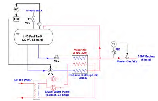
Figure 2 presents the diagram of the FGSS from the LNG fuel tank to the 9L20DF engine, and Table 3 gives the initial operating criteria of the system components (ISO/TC 8, 2014) [17]. The mass flow rate of the LNG fuel was calculated to determine the maximum fuel consumption of 245.4 kg/h. The initial running pressure in the LNG fuel tank was adjusted to 6.5 barg because the master gas valve for the DF engines requires a minimum inlet pressure of 5 barg at normal conditions, according to Wartsila’s 20 DF engine manual. Typically, the operation pressure was approximately 5-6 barg. The tank pressure pushed the LNG toward the LNG vaporizer. Usually all the tank connections and tank vaporizer are enclosed in a cold box as a secondary barrier. A fuel gas heater was employed to provide the vapor at the right temperature via a fuel gas master valve to the GVU. In addition, a 20 °C inlet temperature was applied to the master valve in the simulation model.
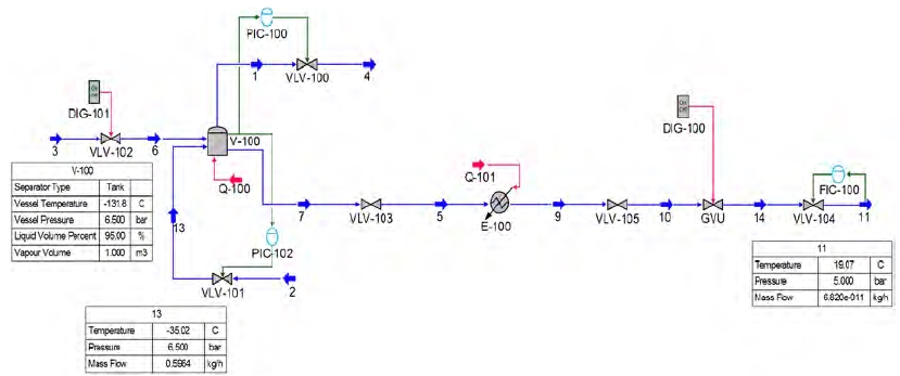
Figure 3 shows the FGSS of Econuri for supplying the LNG to the DF engine using the HYSYS program. The boil-off gas from the LNG storage tank was released if the pressure within the tank exceeded the design pressure with a safety margin. From the storage tank, the LNG flowed into the vaporizer where a water-glycol solution heated the LNG until it was fully vaporized to natural gas. The flow controller (FIC-100) in the system controlled and regulated the mass flow of the natural gas based on its temperature and pressure.
The conditions for the initial starting and normal load procedures were performed through a cooling down process as well as by an auxiliary apparatus including a glycol water pump. However, in the numerical process in HYSYS, the process of cooling down of the LNG fuel tank was not considered. During normal operating loading, fuel gas was supplied to the dual-fuel engine under the conditions of 250 kg/h and 5 barg.
4. Results and Discussion
4.1 Emergency Operation
Safety and stability in the fuel supply system of a DF engine were considered important factors in the case of supply gas cutoff and vaporizer shutdown [18]. In a supply shutdown, the supply gas valve was closed and the gas engine was isolated from the gas network. It was assumed that the GVU signal tripped because of a gas leak or malfunction of the control valve during navigation. In this case, the DF engines were shifted rapidly from the mode of simultaneous combustion of the gas and fuel oil to the mode of combustion of the fuel oil only. Here, the fuel oil was used not only for the ignition during gas combustion but also as the back-up fuel.
Therefore, we examined factors such as the fluctuation of supply pressure, change in flow rate, and the tank pressure for engine shutdown. Figure 4 shows the characteristic curves of the supply gas cutoff on closing of the GVU after approximately 100 min of operation with a 100% load. A drastic increase in the supply pressure is not detected because the valve is shut off. Particularly from the sub-systems of the GVU, the stability is more secure owing to the release of the gas into the atmosphere through purging. Even during emergency condition, as there is no pressure change in the upstream of the GVU, the result presents that the system stability of the fuel gas is certified.
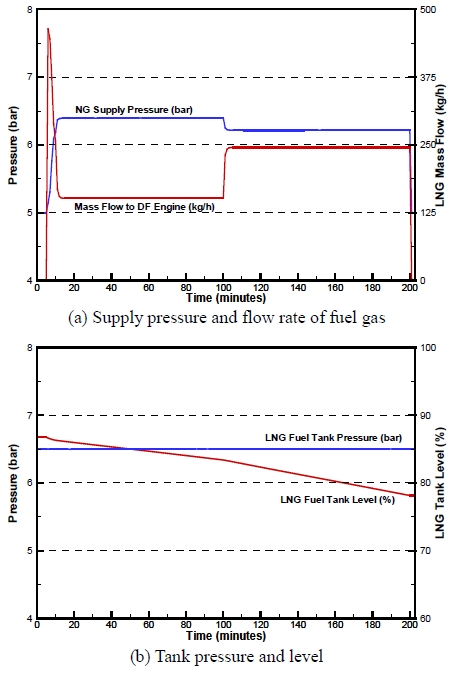
Dynamic curves of the supply gas cutoff from closing of the gas valve unit (GVU) for emergency operation
Moreover, assuming the engine load is 50% during entry into a port or when leaving a port and by conducting sudden veering and steering when making a voyage, we assessed the reliability of the Econuri vessel for a safe stable sailing under the serious conditions. Under these conditions, the engine load was drastically diminished from 90 to 70 % or increased from 50 to 70 %. In a real voyage, as the load fluctuates often due to sudden steering, veering, and ship avoidance, the system stability is an extremely essential element for safety.
Figure 5 presents the dynamic response characteristics of the FGSS in the 9L20DF engine. There is a drastic variation in the gas flow rate when the GVU is opened, but the gas pressure does not show large fluctuations. Subsequently, to sail along the narrow channels for 2 hours, a sudden increase or decreases in the ship speed is required at approximately 50–70 % of the engine output. Thus, the gas supply pressure for the DF engine satisfies the requisite pressure of 6.0–6.5 barg without any variations.
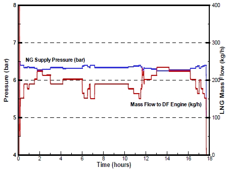
System stability for frequent load variations. The load is drastically diminished from 90 to 70 % or increases from 50 to 70 %.
In addition, despite the drastic change in engine cut down from 90 to 70% of the load, it is proved that the pressure and flow rate of the fuel gas for DF engines maintain a stable reaction without critical fluctuations.
4.2 Estimation of Maximum Navigation Distance without LNG Bunkering
When sailing at the condition of engine loads at 75% or 100%, we estimated the maximum distance that the ship could sail without bunkering. The results can be used as reference data for establishing the navigation plan for the vessel.
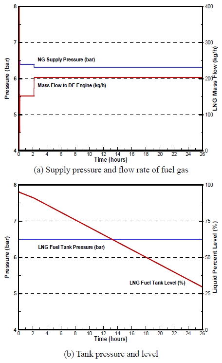
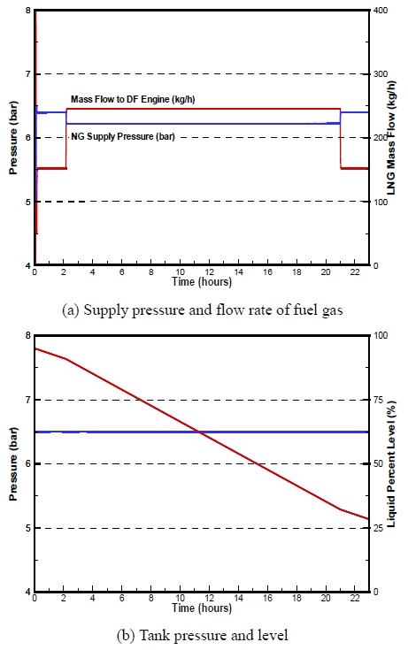
Figure 6 and Figure 7 show the results of the navigation at 75% and 100% load, respectively. Our results reveal that 25 hours of operation are available under 100% load and 31 hours under 75% load without bunkering. Moreover, approximately 694.5 km navigation is possible at a speed of 15.0 knots with 100% engine load and 781 km at a speed of 13.62 knots with 75% engine load, respectively, according to the propeller law. Hence, navigation from the Incheon Port to Gageo Island of South Korea is possible in the absence of fouling and if the sea is calm.
It is shown that there is no problem in conducting the sailing for the maximum distance considering the sudden variations in pressure, flow rate, and other factors in the FGSS without bunkering at 30% volume [10].
5. Conclusion
This study examined the operating characteristics of an LNG-fueled ship with a DF engine having a low-pressure supply system. It also investigated the emergency operation in case of a supply shutdown and determined the maximum navigation distance without LNG bunkering at 30% volume. The first LNG-fueled vessel in Asia, Econuri, of the Incheon Port Authority in Korea, was chosen for the evaluation.
The main results were as follows:
(1) For a failure occurring in the gas system, a supply gas shutdown was considered, and the system returned to the fuel-oil only mode. The review of the system stability of the Econuri vessel revealed that stable operation was possible even at shutdown and for sudden load variation in the gas supply system such as cut-off of the flow rate or fuel pressure. In this case, the DF engines rapidly shifted from the dual-mode of simultaneous combustion of the gas and fuel oil to the single-mode of combustion of fuel oil.
(2) When the Econuri ship operated under the conditions of engine loads at 100% and 75%, the ship in the dual- fuel mode navigated approximately 694.5 km and 781 km, respectively. Hence, navigation from the Incheon Port to the Gageo Island of South Korea, the southernmost island of the Yellow Sea in Korea, was predicted to be achieved without bunkering.
References
- IMO MSC, Second IMO GHG study 2009, Report of the International Maritime Organization, (2009).
- D. L. Gaute, The Future Potential of LNG as a Bunker Fuel, M.S. Thesis, Norwegian University of Science and Technology, Norway, (2011).
-
F. Burel, R. Taccani, and N. Zulianni, “Improving sustainability of maritime transport through utilization of Liquefied Natural Gas (LNG) for propulsion”, Energy, 57, p412-420, (2013).
[https://doi.org/10.1016/j.energy.2013.05.002]

- R. Taccani, F. Burel, and S. Clemente, “LNG powered ships: energy, environmental and economic analysis”, Proceedings of the Second Gas Fuelled Ships Conference, Rotterdam, The Netherlands, (2011).
- J. Harperscheidt, “LNG fuel gas systems for ships other than gas carrier – shipboard systems and infrastructure”, Proceedings of the first gas fuelled ships conference, Hamburg, Germany, (2010).
- B. Scholz, and G. Wursig, , “Bunkering of LNG fuelled vessel technical challenges and perspectives”, Proceedings of the first gas fuelled ships conference, Hamburg, Germany, (2010).
- S. Heo, Concept Design of LNG Bunkering Shuttle with Re-liquefaction Unit, M.S Thesis, Division of Ocean systems Engineering,, KAIST, (2012).
-
G. Livanos, G. Theotokatos, and D. N. Pagonis, “Techno-economic investigation of alternative propulsion plants for Ferries and RoRo ships”, Energy Conversion and Management, 79, p640-651, (2014).
[https://doi.org/10.1016/j.enconman.2013.12.050]

- K. Kim, H. Kang, Y. Kim, and H. Jeon, “Estimation of BOG/BOR in LNG fueled ship with 700 m3 LNG tank during ship-to-ship (STS) bunkering”, The spring proceedings of KOSOMES, p142-143, (2016), (in Korean).
- IMO, International Code of Safety for Ships Using Gases or other Low-flashpoint Fuels (IGF Code), (2015).
- DNV rules, Gas Fuelled Engine Installations, (2011).
- D. Josko, and D. Srdan, “Dual-fuel-electric propulsion machinery concept on LNG carriers”, Transactions on Maritime Science 2014, 2, p137-148, (2014).
- Hamworthy Ltd., LNG fuel systems, http://www.hamworthy.com/Products-ystemsHamworthy-Marine/Gas-System/LNG-fuel-system/ Accessed July 21, 2016.
- J. DiRenzo, Investigation of an LNG Fuel System for a Norwegian Coast Guard Ship, M.S. Thesis, Department of Energy and process Engineering, Norwegian University of Science and Technology, Norway, (2014).
-
J. DiRenzo, P. Neksa, and K. Kolsaker, “Analysis of natural gas engine de-loading on LNG fuelled vessels”, Energy Procedia, 64, p73-82, (2015).
[https://doi.org/10.1016/j.egypro.2015.01.010]

-
Y. Lee, Y. Kim, and H. Kang, “An analysis on the characteristics of regasification system for gas fuelled ship depending on the mixing ratio of eglycol and water”, Journal of the Korean Society of Marine Engineering, 38(7), p799-805, (2014), (in Korean).
[https://doi.org/10.5916/jkosme.2014.38.7.799]

- ISO/TC 8, ISO WG8 LNG bunkering standard outline, (2014), http://isotc.iso.org/livelink/livelink/open/tc8 Accessed May 4, 2014.
-
D. Chang, T. Rhee, K. Nam, K. Chang, D. Lee, and S. Jeong, “A study on availability and safety of new propulsion systems for LNG carriers”, Reliability Engineering & System Safety, 93(12), p1877-1885, (2008).
[https://doi.org/10.1016/j.ress.2008.03.013]


