Fatigue assessment of the propulsion shafting system in eco-ships with an engine acceleration problem
Copyright ⓒ The Korean Society of Marine Engineering
This is an Open Access article distributed under the terms of the Creative Commons Attribution Non-Commercial License (http://creativecommons.org/licenses/by-nc/3.0), which permits unrestricted non-commercial use, distribution, and reproduction in any medium, provided the original work is properly cited.
Abstract
The ultra-long stroke engine (G-type) was developed to generate greater power at lower speeds than previous designs, such as the super long stroke engine (S-type). The new design was intended to improve propulsion efficiency by adopting a higher stroke bore ratio and larger diameter propeller turning at lower speed. In recent cases, however, eco-ships have experienced problems with not passing quickly through the critical speed within the overall range of operating speeds.
This study reviewed the vibration characteristics of a propulsion shafting system installed in eco-ships with G-type engines to determined proper measures for avoiding fatigue fracture of the shafts. Examples of propulsion shafting design for several types of vessels were considered based on a detailed method for shaft fatigue estimation, and the results were compared with those of existing simplified methods such as IACS UR M68 and optimum damper design theory.
Keywords:
Ultra-long stroke engine, Engine acceleration problem, Fatigue fracture, IACS UR M68, Optimum damper design theory1. Introduction
Large scale low-speed diesel engines are widely used for marine propulsion because of their relatively high efficiency compared to existing alternative propulsion systems. Recently, engine makers have developed an ultra-long stroke (G-type) diesel engine with an estimated maximum stroke bore ratio of 5.0 [1]. This type of engine can generate a greater torque than the previous super-long stroke (S-type) engine; yet it is also known to produce an increase of about 30%-40% in torsional exciting force [2]. Moreover, the engine power is optimized for specific operating conditions to improve fuel efficiency by the combination of engine de-rating and tuning technologies.
This properties make it more difficult to control torsional vibration. Thus, torsional vibration dampers are generally applied on vessels equipped with the fuel efficient G-type engines. Previously, the torsional vibration of a vessel could be controlled by applying tuning and turning wheels on each side of an engine. In addition, the derating technology used to reduce fuel consumption can induce insufficient torque in the engine if applied excessively [3][4]. In some recent cases, operators of the fuel-saving G-type engines have experienced engine acceleration problems. This phenomenon can lead to fatigue fracture of its shafts when the vessel remains in a barred speed range for prolonged periods. Unfortunately, the existing simplified method recommended by the international association of classification societies and global shipping registries such as IACS, ABS, DNVGL, Lloyd and KR [5]-[9] does not give suitable methods for calculating the shaft fatigue life of propulsion shafting systems that may be exposed to engine acceleration problems. Therefore, an alternative method [10][11] has recently been developed to assess the shaft fatigue life based on S-N methodology.
In this study, the fatigue strength of the propulsion shafting system in eco-ships was assessed to develop proper measures for avoiding the fatigue fracture of shafts.
2. Engine acceleration problem in Eco-ships
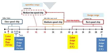
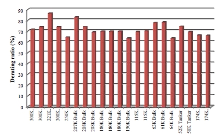
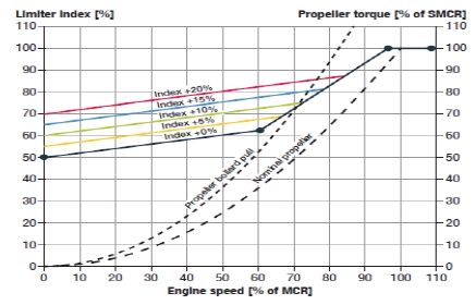
Figure 1 and Figure 2 show the slow steaming [12] and derating technology [13] widely used in eco-ships to reduce fuel consumption. However, it is difficult for the main engine to achieve sufficient torque to accelerate the engine rotation speed at low loads if the engine de-rating ratio exceeds 30%. In the case of a very large ore carrier (VLOC) with excessive de-rating of the engine output, it took several minutes to pass barred speed range in the range of operating speeds. In addition, a large range 2 (LR2) tanker took approximately 1.5 hour to reach the maximum continuous rating (MCR). In order to increase the acceleration capacity of the engine, engine makers (MDT, MAN Diesel & Turbo) have recommended increasing the propeller rpm margin up to 10% above the previous value as shown on Table 1 because the shortage of propeller rpm margin causes this problem [14][15]. However, this recommendation is not appropriate because it reduces the propeller efficiency and fuel efficiency. If the fuel efficiency decreases, there is no point to using a G-type engine. Therefore, alternative methods have been developed to accelerate the engine rpm under low loads, such as the dynamic limiter function (DLF) in the second half of 2015 [16]. This technology is similar to the sport mode function in automobiles. Its purpose is to achieve sufficient engine torque by momentarily injecting more fuel into the cylinder in a low load range to accelerate the engine rpm, as shown in Figure 3. However, this requires precautionary measures because this full DLF mode increases thermal load and vibratory torque.
In another case, a VLOC with a G- type engine and de-rating technology experienced an accident. In the case of this vessel, the rpm acceleration was delayed due to lack of torque capacity in the low load range, which resulted from excessive de-rating of up to 36%.
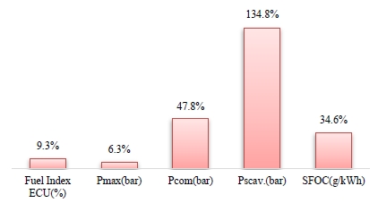
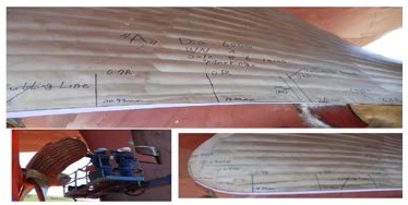
Currently two measures are used for existing ships: propeller edge cutting to increase the margin of the propeller rpm, and modifying the engine parameters below a 50% load, which increases the scavenge air pressure and quantity of fuel injected to increase the torque capacity, as shown in Figure 4. In general, propeller edge cutting is carried out to increase the margin of propeller rpm in aging ship. However, this above VLOC applied propeller edge cutting as shown in Figure 5 despite being a new ship because it was necessary to increase the margin of propeller rpm from 1 to 5%. The VLOC adopted both measures because only propeller edge cutting did not reduce the time spent in the barred speed range. With both measured, the time spent in the barred speed range was shortened.
3. Shaft fatigue life assessment methods
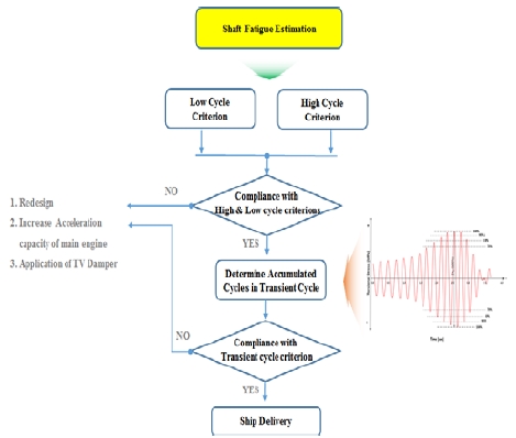
There are two approaches to assessing the shaft fatigue life. One includes simplified methods such as IACS UR M68, which use the torsional stress at the steady state; the other includes detailed methods based on the S-N methodology. IACS UR M68 is recognized as simple to use in the frequency domain; however, it has limited application if the time spent in the barred speed range exceeds 4-5 seconds. This is because this range is considered a transient state and not a steady state. Therefore, it is necessary to use the detailed method based on the S-N methodology to assess the shaft fatigue when the time a vessel spends in this range exceeds 5 seconds. Figure 6 shows how to estimate the shaft fatigue strength. There are three criteria: low, high, and transient cycles. Relevant shaft designs have to satisfy the low and high cycle criteria first before determining the accumulated number of cycles in the transient range. The shaft design then has to satisfy the transient cycle criterion. If these criteria are not satisfied, three possible options can be considered: redesigning the shaft, increasing the acceleration capacity of the engine, applying an optimum torsional vibration damper to reduce the stress on the shaft.
4. Case study of shaft fatigue life assessment for eco-ships with engine acceleration problems
In this study, three type of eco-ships were reviewed, and proper measures were evaluated for avoiding the fatigue fracture of shafts during the vessel life expectancy (25 years). Table 2 presents the specifications of ships with acceleration problems owing to insufficient torque from the main engine. These vessels had G-type engines with excessive de-rating; during sea trials, it took about 20 seconds for them to pass through the barred speed range. This range should usually be passed rapidly (within 4-5 seconds) for simplified methods such as IACS UR M68 to be applicable. However, the IACS UR M68 calculates the steady-state torsional vibratory stresses, while this case is a transient state. Therefore, shaft fatigue needed to be assessed with a detailed method based on the S-N methodology for the transient state. Table 3 presents the results of the shaft fatigue assessment. The torsional vibratory stress in the transient state was assumed be to less than the steady-state value by 20%, and the number of cycles in the barred speed range during the vessel life expectancy was assumed to be 5,000. The allowable time to pass through the barred speed range was over 20 seconds. According to the shaft fatigue assessment with the detailed method, safe operation was expected throughout the vessel life even though the actual time needed to pass the barred speed range exceeded 4-5 seconds. In conclusion, the shaft fatigue life should be assessed with the detailed method rather than IACS UR M68 if the time for the vessel to pass through the barred speed range exceeds 4-5 seconds.
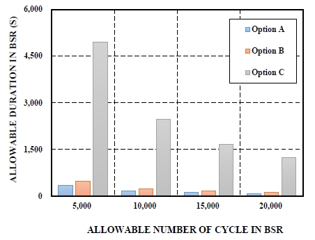
In order to address this problem more actively, there are three possible options to increase the allowable passing time and number of cycles in the barred speed range by changing the shaft material and fillet design, as given in Table 4. The stress concentration factor in the shaft flange can be reduced by using a multi-fillet design, and the fatigue strength of its shaft can be increased by using alloyed steel instead of forged steel.
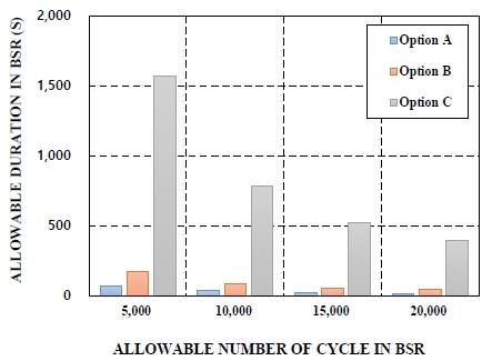
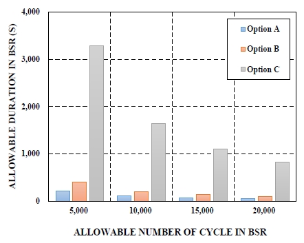
The sample vessels in Table 2 were also used to examine the effect of each design option. The operating life was assumed to be 25 years, and the torsional vibratory stress in the transient state was 20% less than the simulated values in the steady state. Figures 7 ~ Figure 9 show the correlation between allowable passing time and number of cycles in the barred speed range with each design option. The allowable number of cycles for existing shafts of forged steel, such as SF600, could be increased by changing the shaft flange design from single-fillet to multi-fillet. In addition, both the allowable duration and number of cycles in the barred speed range could be increased by using alloyed steel instead of forged steel with multi-fillet. Therefore, if a vessel is expected to have trouble with quickly passing through the barred speed range in the design stage, the usage of alloyed steel with a multi-fillet design can be considered.
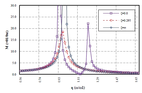
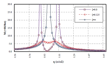
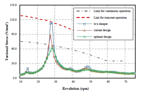
Other alternatives such as torsional vibration damper optimization based on the optimum damper design theory [4][17][18] can also be considered to eliminate the barred speed range in the operating speed range. Figure 10 shows the dynamic characteristics of an existing damper applied to a 300K VLCC. As shown in Figure 10, the dynamic magnitude was as high as 18.4. After calculating the optimum stiffness and damping coefficient ratio by the process of optimum damper design theory, and maintaining the current inertia value of the damper, the results were 8.3 MNm/rad and 0.125, respectively. This outcome is 27.8% and 57.6% lower than the existing design. Figure 11 shows the dynamic characteristics of the modified damper applying the optimum stiffness and damping coefficient, and calculated using the optimum damper design theory. The dynamic magnitude is about 6.5, which is 64.7% lower than that of the existing damper. Figure 12 shows the vibration characteristic of its shafting system with the modified damper design. The torsional vibratory stress in the intermediate shaft could be reduced to 61.9 N/mm2 which is 29.2% lower than that of the existing damper design. Therefore, the barred speed range could be eliminated by reducing the torsional stress in shafts below the limit line for continuous operation. Consequently, the time spent passing through the barred speed range would no longer need to be considered.
5. Conclusions
This study reviewed the optimum design of a propulsion shafting system equipped with ultra-long stroke engines in ecoships that have recently had engine acceleration problems. In order to avoid fatigue fracture of its shafting system due to accumulated cycles in the barred speed range, the shaft fatigue was assessed by using a detailed method based on S-N methodology instead of the IACS UR M68, which is recognized as simple to use in the frequency domain. To address this problem more actively, possible design options for increasing the allowable passing time and number of cycles in the barred speed range or even eliminating the barred speed range were reviewed. Measures were suggested to cope with this problem. The following conclusions were derived.
(1) Fuel-saving technologies such as slow steaming and derating provide ship owners opportunities to adjust to the global economic downturn but can lead to engine acceleration problems if the de-rating is excessive. Unfortunately the existing IACS UR M68 is not a suitable method for calculating the shaft fatigue life of propulsion shafting systems that might be exposed to engine acceleration problems. Therefore, an alternative method based on S-N methodology that assesses the shaft fatigue life in more detail is necessary.
(2) In general, existing shaft designs do not adequately address the engine acceleration problem when the passing time in the barred speed range exceeds 4-5 seconds. Therefore, proper measures for increasing the shaft fatigue life in the design stage are required. A multi-fillet design for the shaft flange and higher-grade shaft material (e.g., alloyed steel) are presently suitable measures for effectively lengthening the fatigue life of a shaft.
(3) If a ship is expected to have passing time through the barred speed range or an excessive cumulative number of cycles in the barred speed range, the barred speed range can be eliminated from the operating speed range. It was confirmed that the torsional vibratory stress in shafts can be reduced below the limit line for continuous operation by means of an optimum damper based on optimum damper design theory.
Acknowledgments
This paper is extended and updated from the short version that appeared in the Proceedings of the International Symposium on Marine Engineering and Technology (ISMT 2016), held at Korea Maritime and Ocean University, Busan, Korea, November 3-4, 2016.
References
- MAN Diesel & Turbo, G-type Engine-revolutionary Ultralong Stroke, MAN Diesel & Turbo, Copenhagen, Denmark, (2010).
- Y. G. Kim, S, J. Hwang, J. S. Sun, S. G. Jung, and U. K. Kim, “A study on the effect of torsional vibration for propulsion shafting due to the characteristics of fuel saving marine engine”, Proceedings of the 39th Korean Society of Marine Engineering Fall Conference, p186, (2015), (in Korean).
- Y. G. Kim, S. J. Hwang, Y. H. Kim, K. H. Cho, and U. K. Kim, “A control of torsional vibration for propulsion shafting by optimum design of geislinger tuning damper for eco-ship with delayed rpm acceleration of marine diesel engine”, Proceedings of the 40th Korean Society of Marine Engineering Spring Conference, p173, (2016), (in Korean).
-
Y. G. Kim, S. J. Hwang, Y. H. Kim, S. W. Kim, K. H. Cho, and U. K. Kim, “Control of torsional vibration for propulsion shafting with delayed engine acceleration by optimum design of a viscous-spring damper”, Journal of the Korean Society of Marine Engineering, 40(7), p580-586, (2016), (in Korean).
[https://doi.org/10.5916/jkosme.2016.40.7.580]

- IACS, M68: Dimension of Propulsion Shafts and Their Permissible Torsional Vibration Stresses, IACS, London, United Kingdom, (2015).
- ABS, Rules for Building and Classing; Steel Vessels, ABS, Huston, United States of America, (2016).
- DNVGL, DNV GL Rules for Classification: High Speed and Light Craft (RU-HSLC), DNV GL, Oslo, Norway, (2016).
- Lloyd’s, Rules and Regulations for Classification of Naval Ships, Lloyd’s Register, London, United Kingdom, (2016).
- KR, Rules for the Classification of Steel Ships, Korean Register, Pusan, Republic of Korea, (2016).
- DNV-GL, DNVGL-CG-0038: Calculation of Shafts in Marine Applications, DNV GL, Oslo, Norway, (2015).
- KR, Guidance for Shaft Fatigue Estimation, Korean Register, Pusan, Republic of Korea, (2016).
- R. Werrstein, and D. Brown, Derating: A solution for high fuel savings and lower emissions, Wartsila Corporation, (2008).
- J. R. P. Osses, and R. W. G. Bucknall, On the Impact of Marine Engineering Efficiency with De-rated Engines: A Study Using VLCCs, Low Carbon Shipping Conference, (2013).
- MAN Diesel & Turbo, Market Update Note-Light Running Margin (LRM), MAN Diesel & Turbo, Copenhagen, Denmark, (2015).
- Winterthur Gas & Oil, High Torque Reserve of RT-flex and X-engines for Adequate Ship Acceleration, Winterthur Gas & Oil, Winterthur, Switzerland, (2015).
- MAN Diesel & Turbo, Market Update note-enhanced Torque Reserve for MAN B&W S and G-type Engines for Adequate Ship Acceleration, MAN Diesel & Turbo, Copenhagen, Denmark, (2015).
- W. K. Wilson, Practical Solution of Torsional Vibration Problems, 1-5, Chapman & Hall, London, (1942).
- BICERA, Handbook of Torsional Vibration, Cambridge University Press, (1958).
