Feasibility study of corner reflector for radar countermeasures and deception for conventional forces

Copyright © The Korean Society of Marine Engineering
This is an Open Access article distributed under the terms of the Creative Commons Attribution Non-Commercial License (http://creativecommons.org/licenses/by-nc/3.0), which permits unrestricted non-commercial use, distribution, and reproduction in any medium, provided the original work is properly cited.
Abstract
The high-tech large warships are minimal and they are always monitored by opponents, and become primary targets when conflicts occur. The improvement in reducing susceptibility has significant importance because it is difficult for a ship to maintain mission capability and functionality once it is damaged. Ordinary decoys are effective only under the premise that the ship has already been exposed. Traditionally, for naval vessels, techniques related to the radar have been used in military stealth techniques to ensure confidentiality. The corner reflector, on the other hand, can produce rather large radar cross sections. Continued use of deceptive systems such as chaff during operations will help to improve survivability of naval ships. From this viewpoint, corner reflector was considered for making radar countermeasures and deception technology. This paper reviews the current status of corner reflector basis decoys and the technical feasibility of corner reflectors for developing structural decoys.
Keywords:
Susceptibility, Decoy, Corner reflector, Radar countermeasures, Deception1. Introduction
As the modern destroyer possesses remote attack capabilities from any location at sea, it has become the leading vessel in EBO (Effects-based Operations) and NCW (Network-centric Warfare) [1][2]. As most of the countries have only a few destroyers as their flagships, their status of maneuvers and operations are continuously monitored by other countries. Once a conflict occurs, these ships become primary targets for concentrated attacks. As today’s attacks are so diversified and intensive, once a ship gets hit, it can hardly maintain its mission capability or functionality [3]. In most cases, the locations and paths of the flagships and the size of the accompanying fleet are predicted based on previously monitored information. Therefore, protecting these ships from opponent surveillance, tracking, and threats receives the highest priority. Reduction in susceptibility is one of the topics in survivability that has led to intensive studies in technological development along with the increased focus on reducing vulnerabilities and increasing recoverability.
2. Ship Survivability and Susceptibility
The survivability of a ship consists of three temporal elements: susceptibility, vulnerability, and recoverability as shown in Table 1[4].

Key elements of survivability of a ship
The survivability of a ship can be described as a temporal chain, as shown in Figure 1[5].

Example of the time based hit process of a ship
Improvements in survivability through reduction in vulnerability and increase in recoverability fall into the category of ‘Don't get killed.’ However, once a ship is damaged, a significant amount of time is required to secure its structural safety, and recover its functionality and mission capability. To make the situation worse, advancements in modern weapon systems make it difficult for the ship to recover from damage. Therefore, reducing susceptibility during the entire operational phase is important. The application of signature control during the ship acquisition process is limited because the geometry of a ship affects the arrangement of the main equipment and the compartment layout. During the operational phase, the soft kill and hard kill systems allow only a few seconds to make a decision when under attack. This is because, a ship in a war will be directly engaged in combat after it is detected and identified. Therefore, there is an urgent need for deception technologies that will prevent the ship and its operational fleet from being detected and traced. One of the most promising solutions to this problem is the corner reflector-based radio frequency (RF) decoy that uses corner reflectors, which are usable through the entire operational period.
3. Reduction in Susceptibility via the Decoy System
A warship emits a unique RF signature which is distinct from that of other civil vessels. Therefore, the opponents’ on-board or on-the-ground radars are able to continuously trace the location and path of the warship.
This fact has led to the need for dealing with the signature to mask the actual location or path of the ship. However, many deception systems are in using for deceiving the threat as they emit a significantly more intense signature than that of what the ship normally emits under attack. So, nowadays corner reflectors are used to disrupt the opponent’s radar detection capabilities [6][7]. The current corner reflector based decoys have larger radar cross section (RCS) compared to a ship. The RCS generally yields higher values at the cardinal points of the vessel and significantly varies with the relative geometry of the ship to the radar. As the corner reflector based decoy fails to follow the RCS variation of the ship, a simple algorithm can distinguish the ship from surrounding decoys in the mixed radar signature. Figure 2 shows how different the behavior of the current corner reflector based decoy is from that of a ship in terms of the relative position of the radar.

Comparison of the RCS areas for the ship and decoys in terms of relative distance from the radar
4. Radar Countermeasures and Deception using Inflatable Corner Reflectors
Although unmanned systems and satellites are evolving with Electro Optics (EO) and Infrared (IR) sensors, corner reflector decoys are still effective choices in neutralizing the attempts of an opponent’s radar to detect the ship. As in electromagnetic analysis, RCS, σ is commonly written as [8]:
| (1) |
where Es and Ei are the scattered and incident electric field intensities, respectively. As the current decoys require improvement in order to accurately imitate the varying RCS area, one feasible idea is to work with the scattering points of the vessel. As the corner reflectors are systematically arranged and combined to correspond to each of the analyzed scattering points, the corner reflector decoys can be configured to have similar RCSs to those of the actual vessel. Taking into account these scattering points, a ship’s RCS σ can be written as follows:
| (2) |
where N is the number of scattering points, is the signal strength of nth scattering point, and φ is the phase differences.
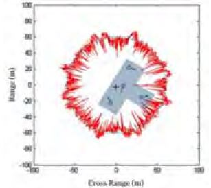
Figure 3 illustrates how the RCS of a vessel is imitated using the modularized corner reflectors. Analysis of the scattering points can be conducted through the use of a range profile or commercial RCS analyzing tools [9].
For making modularized corner reflectors, tri-hedral corner reflectors are considered, because it can produce relatively larger RCS [10]. According to IMO performance standards, a corner reflector has a detection range of 5.0 NM in the X band and 3.7 NM in the S band [11][12].

Concept of RCS imitation using the scattering point of the vessel
The diameter of a round-shaped multi-hedral corner reflector is approximately 0.32 m and the width of a square-shaped multi-hedral corner reflector is approximately 0.26 m. Putting these values in Equation (2) theoretically yields an RCS of 10 m2 in an X-band radar [13]. However, on the actual sea, it is difficult to obtain the theoretical RCS value due to the influence of waves and the frequent phase changes of the RCS reflector due to the wind [14]. To have an appropriate RCS, a corner reflector should have an appropriate height rising from the sea surface. Required height can be calculated from the following formula [15]:
| (3) |
Taking into account the above requirements, this paper considers a method of embedding a corner reflector inside a floating balloon.
As a modularized floatable corner reflector acts as a single scattering point, the size and number of corner reflectors can be varied as needed. In this paper, we have constructed a multi-hedral corner reflector with a diameter of 40 cm embedded balloon, which is somewhat larger than the theoretical value because we considered the influence of waves, wind and the infantry power of balloon. The RCS value of the X-band radar in the actual sea area has been measured in Noksan-dong, Busan, Korea as shown in Figure 4. In the test, technical possibility has been checked that the RCS signal can be simulated similar to the scattering point extraction result of the real naval vessel when the unit corner reflector is superimposed at a certain distance.

Test area in Busan Korea
Figure 5 shows the geometrical design concept of the modularized corner reflector, computational simulation and maritime test results. As shown in Table 2, the floating height of the corner reflector is affected by the wind. The corner reflector detected up to 1.08 nautical miles on the X-band commercial radar which is approximately 15 m above the sea surface. Detectable range certainly varies with the height and phase of the corner reflector and also from the radar performance. Although it still has limitations and rooms for improvement, technical feasibility of radar countermeasures and deception with floatable modularized corner reflectors is convincing. In order to develop corner reflector based radar countermeasures and deception technology, additional theoretical and maritime experiments with various sizes and combinations of modularized corner reflectors are required in the near future. Table 3 shows a sample test result of combined corner reflectors [16]. From this simulation result, specific combination algorithm for imitating a ship’s RCS will be investigated in a follow up study.

Example of experimental technical feasibility review for radio frequency (RF) signal imitating
Test results of radar detection range
Example of simulation results of asymmetrically combined corner reflectors
5. Conclusion
This study reviewed the characteristics and limitations of existing decoys. In addition, this study explored the extent of improvement in existing corner reflector-based decoys for radar countermeasures and deception during a ship’s operation. Although continuous advancements in remote surveillance and improvements in weapon system performance may gradually decrease the usefulness of the proposed modularized corner reflector-based decoy, it is still effective in deceiving the ground and maritime radars of the fleet size and aim of the operation. Additional research on algorithms for arranging and combining modularized corner reflectors will be performed in a follow up study.
Acknowledgments
This research was supported by the inherent research projects of KRISO, PES8890 and PNS2790. Some parts and initial concept of this paper have been introduced in Proceedings of Naval Ship Technology Seminar which was held in Busan, Korea 2013 and previous version of this paper has been introduced in Proceedings of International Naval Engineering Conference and Exhibition which was held in Bristol, UK 2016.
References
- L. D. Popescu, “Effects-based Operations and Knowledge-based Society,”, International Scientific Conference "Strategies XXI", "Carol I", National Defence University, p95, (2014).
- J. Xu, L. Duan, and Q. Y. Li, “The design of mission-oriented management system for multi-sensors network in network-centric warfare,”, Proceedings of IEEE Control and Decision Conference 2014, p2470-2475, (2014).
- K. Lippold, Front Burner: Al Qaeda's Attack on The USS Cole, PublicAffairs, (2013).
-
E. Boulougouris, and A. Papanikolaou, “Risk-based design of naval combatants”, Ocean Engineering, vol. 65, p49-61, (2013).
[https://doi.org/10.1016/j.oceaneng.2013.02.014]

- B. A. Bloye, Optimizing the Air-to-Ground Kill Chain for Time-Sensitive Targets, M.S. Thesis, Naval Postgraduate School, Department of Operations Research, Naval Academy, USA, (2009).
- H. Bannasch, and M. Fegg, “Method and apparatus for protecting ships against terminal phase-guided missiles,”, U.S. Patent 7886646, Feb. 15, 2011.
- N. Prelic, and H. Eglauer, “Activation unit for munitions-free decoy target,”, U.S. Patent 8820244, Sep. 2, 2014.
- J. J. Crispin, Methods of Radar Cross-section Analysis, Elsevier, (2013).
- K. H. Kim, J. H. Kim, and D. S. Cho, “A study on the effective scattering center analysis for radar cross section reduction of complex structures”, Journal of the Society of Naval Architects of Korea, vol. 42(no. 4), p421-426, (2005), (in Korean).
-
X. J. Shan, J. Y. Yin, D. L. Yu, C. F. Li, J. J. Zhao, and G. F. Zhang, “Analysis of artificial corner reflector's radar cross section: A physical optics perspective”, Arabian Journal of Geosciences, vol. 6(no. 8), p2755-2765, (2013).
[https://doi.org/10.1007/s12517-012-0582-x]
- A. G. Bole, A. D. Wall, and A. Norris, Radar and ARPA Manual: Radar, AIS and Target Tracking for Marine Radar Users, Butterworth-Heinemann, (2013).
- IMO, Resolution MSC.192(79), (2004).
-
H. J. Kang, D. Lee, J. G. Shin, C. S. Park, B. J. Park, and J. Choi, “A study of a rescue device for marine accidents using radar cross section characteristics”, Marine Technology Society Journal, vol. 42(no. 4), p38-44, (2008).
[https://doi.org/10.4031/002533208787157732]
-
K. H. Kim, and D. S. Cho, “Study on effect of shell plate deformation to radar cross section of warship”, Journal of the Society of Naval Architects of Korea, vol. 48(no. 6), p509-515, (2011), (Korean).
[https://doi.org/10.3744/snak.2011.48.6.509]
- I. Harre, RCS in Radar Range Calculations for Maritime Targets, Bremen, Germany, (2004), Available: http://www.mar-it.de/Radar/RCS/RCS_xx.pdf Accessed January 22, 2017.
-
H. J. Kang, J. G. Shin, K. Kim, Y. Yang, and H. K. Yang, “Accident scenarios-based detail design of a life-saving appliance for search and rescue activities”, Marine Technology Society Journal, vol. 48(no. 1), p49-65, (2014).
[https://doi.org/10.4031/mtsj.48.1.4]