Operating characteristics of 3RT heat pumps

Copyright © The Korean Society of Marine Engineering
This is an Open Access article distributed under the terms of the Creative Commons Attribution Non-Commercial License (http://creativecommons.org/licenses/by-nc/3.0), which permits unrestricted non-commercial use, distribution, and reproduction in any medium, provided the original work is properly cited.
Abstract
Newly designed vapor-injection heat pumps have been proposed and analyzed in the present study. An economizer-type vapor-injection (V-I) system has been employed as the standard system because of its reliability and simple control method. The V-I system has a re-cooler and re-heater for cooling and heating, respectively. Solar panels have been installed in the V-I heat pump as well as in the re-heater in order to enhance heating capacity and performance. R410A has been employed as a working fluid and performance analysis has been conducted under various conditions. Results are summarized as follows: (1) The V-I system with the re-cooler yielded a marginally higher coefficient of performance (COP) than the conventional V-I refrigeration system. (2) By increasing the re-cooler cooling capacity, enhanced system performance as compared to the conventional V-I system was observed. (3) The re-heater negatively affected the system performance; hence, the V-I heat pump with the re-heater yielded a lower COP than that of the conventional V-I heat pump used for heating. (4) Although the solar panels increased the system performance, this increase could not offset performance degradation by the re-heater.
Keywords:
Vapor-injection, Re-cooler, Re-heater, Heat pump1. Introduction
Vapor-injection heat pumps are widely studied because of their enhanced system performance reliability. Vapor injection into a compressor causes the discharge temperature from the compressor and the power consumption to decrease; this consequently increases the coefficient of performance (COP) of the system. Many studies have applied the V-I system in various circumstances requiring a high pressure ratio because it affords the benefit of power input reduction. Ma et al. [1] conducted an experimental investigation of the V-I heat pump for cold regions. They concluded that the V-I heat pump improved the heating capacity and system performance as compared to the conventional air source heat pump, and that the degree of advance increased with an increase in the compression ratio. Ma and Zhao [2] studied V-I heat pumps with flash tanks (FTs). They experimentally investigated the V-I FT system and compared it to the V-I system with an applied economizer (ECO). The results showed that the V-I FT system was more efficient than the V-I ECO system. Hwang et al. [3] conducted an overall review of studies on refrigerant injection techniques. They reviewed not only the V-I systems, but also a liquid-injection system. They mentioned that, with regard to the COP, the V-I FT system was more efficient than the V-I ECO system; however, the ECO system exhibited a wider injection pressure operating range. They also indicated that the FT system mandates a more expensive throttling device and complex control method than the ECO system, though the components of the FT system are simpler than those of the ECO system. Mathison et al. [4] proposed a heat pump system with a saturation cycle. The saturation system compresses the refrigerant according to the saturation vapor line and throttles it along the saturation liquid line. As practical feasibility of this type of heat pump proved difficult, they suggested applying multiple injection ports and flash tanks in order to best reproduce the saturation cycle. The results showed that 1) the heat pump performance improved between 18% and 51% and 2) that the scale of performance enhancement increased as the heat pump operated more in the critical condition.
Subsequent to investigations into published literature, the V-I heat pump has been simulated and tested, and an improved design has been proposed. Many researchers concluded that the V-I heat pump is more efficient than the conventional vapor compression heat pump. V-I system comparison confirms the following: although the FT-type system yields a higher COP than the ECO type, there are significant problems with the V-I FT heat pump mandating a complex control method for stable operation. Moreover, the FT-type system has the problem of liquid backflow caused by incomplete separation from the flash tank; thus, it requires a specific flash tank design. Considering this, the V-I ECO system is believed to be superior to the V-I FT system in terms of stability and accessibility.
This paper proposes new designs for V-I heat pumps, modified to incorporate additional equipment, such as a re-cooler, re-heater, and solar panels, in order to achieve a level of performance that is superior to that of the conventional V-I heat pump; additionally, the effectiveness of the newly proposed systems is analyzed and validated by comparing them to the conventional V-I system. Analysis of the two types of V-I systems mentioned above led to the utilization of the V-I system with the applied economizer as the basic system, as the V-I ECO system yields advantage over the V-I FT system in terms of control.
2. Cycle descriptions and analysis conditions
2.1 Cycle descriptions
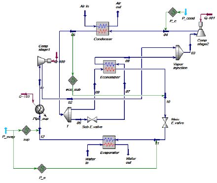
Figure 1 shows the conventional V-I system. Compressed vapor discharged by the compressor passes through the condenser and becomes a subcooled liquid; then, the condensed refrigerant follows one of two paths. One path is throttled by a sub-expansion valve, while the remaining path proceeds directly to the economizer. The expanded refrigerant cools the non-expanded refrigerant by running through the economizer.
The lower temperature liquid refrigerant is then expanded by a main expansion valve before being evaporated in an evaporator. By-passed and heated refrigerant is injected into the injection port of the compressor and merged with the refrigerant from the evaporator during the compression process. The system configurations are essentially the same, regardless of the system purpose, i.e., cooling or heating; however, areas of application differ.
Cooling and heating in the V-I system is performed via an evaporator and condenser, respectively.
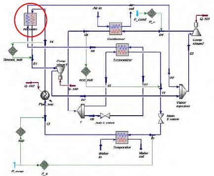
Figure 2 depicts the V-I system with an applied re-cooler. The system operates in the same way as the conventional system shown in Figure 1, with the exception of there being an added component, i.e., the re-cooler. Refrigerant from the economizer absorbs heat from the evaporated refrigerant by passing through the re-cooler. Consequently, the suction line temperature and required amount of compression is reduced, thereby increasing the system COP.
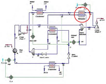
Figure 3 illustrates the V-I heat pump with the re-heater. The system employs the re-heater in order to increase the temperature of the by-passed refrigerant from the economizer. The re-heater exchanges heat between the by-passed refrigerant from the economizer and the discharged refrigerant from the compressor. Although it transfers heat between the inlet and outlet refrigerant of the compressor, the system is simulated, as it may yield desirable effects on the heating capacity.
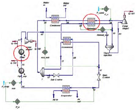
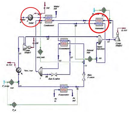
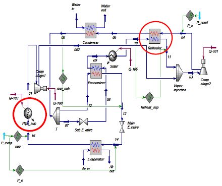
Additionally, the solar panels have been installed in the re-heater-applied V-I system in order to enhance the heating capacity and system performance. Figures 4, 5, and 6 illustrate varying configurations of the V-I heat pump with an applied re-heater and solar panels. Figure 4 shows the solar panels installed on the suction line to increase the evaporating pressure and temperature. Although the heat from the sun does not directly affect system capacity, it can increase the evaporation pressure, which subsequently decreases the system pressure ratio. Figure 5 shows the solar panels installed outside of the system to pre-heat the water before it flows through the condenser. By installing the panels outside of the system, it is possible to provide direct heat to the water. Finally, Figure 6 shows the solar panels installed in a position that precedes that of the re-heater; this was purposed to provide additional heat to the compressor. The sun provides direct heat to the system, a feature that differs from the remaining systems. Each of the systems shown in Figures 4, 5, and 6 are expected to discharge high temperature refrigerants that consequently increase the heating capacity.
2.2 Modelling
Aspen HYSYS version 8.6 [5] has been selected as the simulator program, and the Peng–Robinson equation of state [6] as the thermodynamic package. The package has been employed because it can calculate the thermodynamic processes of refrigeration systems with high accuracy.
Following are the assumptions applied in the system modeling.
1) The refrigerant in the compressor is compressed adiabatically.
2) Pressure drops and heat losses in the heat exchangers and pipes are negligible.
3) Refrigerants in the expansion valves yield isenthalpic processes.
4) The injection process is an isobaric process.
3. Results and discussions
3.1 Cooling
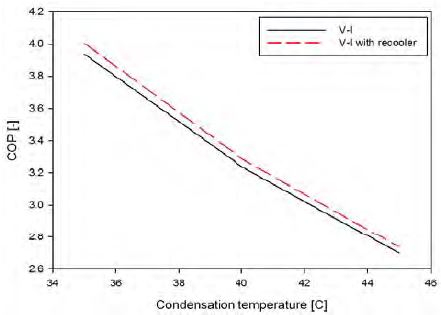
Figures 7 to 11 demonstrate COP variations in the refrigeration system cooling as a function of the various parameters given in Table 1. Figure 7 illustrates COP as a function of condensing temperature. As the condensing temperature increased, the system COP decreased. This is because a higher condensing temperature generated a higher pressure ratio, which therefore mandated an increase in power consumption to generate the same cooling capacity. A system comparison revealed the following: the COP of the system equipped with a re-cooler is higher than that of the conventional V-I system. However, this difference in COP decreased from 1.73% to 1.38% as condensing temperature increased. More explicitly, re-cooler installation yielded optimized system performance at lower condensing temperatures.
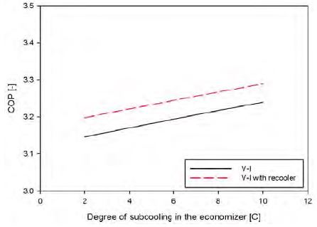
Figure 8 demonstrates COP variation with respect to the degree of subcooling in the economizer. The system COP increased with increased economizer subcooling as a result of the increased enthalpy difference in the evaporator. Because of this increase, the mass flow rate in the evaporator and the total amount of compression were reduced. The system performance was also enhanced by the re-cooler. The re-cooled V-I system consistently yielded a 1.59% higher COP as compared to the conventional V-I system.
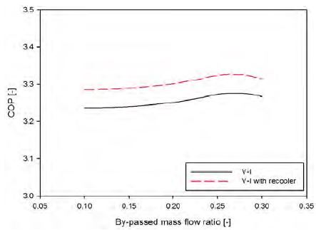
Figure 9 shows the COP as a function of the by-passed mass flow ratio. The by-passed mass flow ratio is defined as the ratio of the by-passed mass flow rate measured at the condenser exit to the mass flow rate in the condenser. Increase in the by-passed mass flow ratio caused the cooling capacity of the evaporator to increase because of an increased enthalpy difference. Because the mass flow rate of the injected refrigerant increased as well, the amount of compression also concurrently increased. Although the increase of cooling capacity initially yielded more significant effects on system performance than the increase in power consumption, the amount of compression became increasingly more significant as the by-passed mass flow ratio increased. Consequently, the system exhibited optimized performance when the mass flow ratio was approximately 0.25. As is shown in Figure 8, the V-I system with the re-cooler yielded a 1.53% higher COP than the conventional system on average.
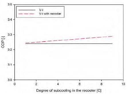
Figure 10 plots the system performance as a function of re-cooler subcooling degree. The system COP increased with increased re-cooler cooling capacity; this is because the re-cooler reduced the amount of required compression.
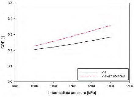
Figure 11 illustrates COP variation with respect to intermediate pressure. The standard intermediate pressure was set as 1200 kPa; this value was calculated and simplified according to the following equation:
| (1) |
Pm, PH and PL represent the intermediate, condensing, and evaporating pressure, respectively. Although the system performance exhibited improvement with a medium pressure increase, system stability and economizer performance declined because the temperature difference between the inlet and outlet of the economizer had decreased. In practice, the HYSYS program presented an error, indicative of a temperature difference in the economizer owing to reduced stability above 1200 kPa of intermediate pressure. Hence, the V-I systems with 1200 kPa of medium pressure yield the highest COP among the realizable intermediate pressure conditions in Table 1.
3.2 Heating
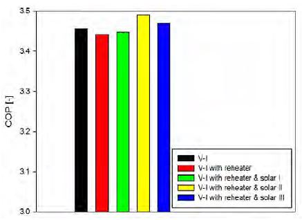
A heat pump performance comparison is presented in Figure 12. Incongruent with the assumption mentioned in Section 2.1, the system performance declined even with an installed re-heater. The re-heater exchanged the heat between by-passed and discharged refrigerants, as mentioned above. Because of this heat transfer, the refrigerant temperature at the condenser inlet decreased; this reduction is more significant than the temperature increase of the discharged refrigerant resulting from an injection of relatively hotter vapor into the compressor; this process caused the heating capacity to decrease. Applying the solar panels resulted in a 1% and 0.41% marginal increase in system COP for Alignments 2 and 3, respectively. Conversely, Alignment 1 yielded a lower COP than the standard V-I heat pump. Consequently, the re-heater was found to yield undesirable effects on the V-I heat pump system in terms of system performance. In addition, the re-heater was found to yield adverse influence on the compressor because of an increased discharge temperature that is hypothesized to eventually lead to compressor breakdown with continuous use.
4. Conclusions
Applying new configurations to the conventional V-I system has been proposed and simulated in this study. The re-cooler was applied to the V-I system for cooling and the re-heater and solar panels were incorporated into the V-I system for heating. The systems were classified according to their respective purpose of either cooling or heating; additionally, a comparison analysis was performed.
For cooling, the V-I system and V-I system with the re-cooler were both analyzed and subsequently compared with respect to their effects on the COP. The V-I system with the re-cooler consistently yielded a marginally higher COP than the conventional V-I system because the re-cooler reduced the amount of compression before the injection. Although the re-cooler improved the COP by less than 2%, this margin may be augmentable if the cooling capacity of the re-cooler can increase without affecting system stability.
For heating, the re-heater yielded undesirable effects on the system performance. Although it was able to increase the discharge temperature of the compressed refrigerant by passing it through the re-heater, heat loss due to the re-heater offset the heat gain from the re-heater. Thus, the heat gain can be considered negligible as the refrigerants between the inlet of the injection port and outlet of the compressor exchange heat. The heated refrigerant was injected into the compressor and cooled by the re-heater before being passed through the condenser; thus, it loses the heat gain before being able to contribute to the heating capacity. The heating capacity was observed to have been further reduced by heat loss in the re-heater, as the effectiveness of the heat exchanger was not ideal. In addition, the high discharge temperature due to the re-heater is hypothesized to cause damage to the compressor similar to that observed when a conventional vapor compression heat pump is employed in a cold environment. In conclusion, the re-heater was found to have an adverse influence on, not only the system performance, but also the compressor. Contrary to the re-heater, the solar panels were found to positively affect system performance. However, the enhanced performance resulting from solar panel application was unable to offset the performance degradation resulting from re-heater application in the present study because of the insufficient heating capacity. The system performance may be improved by applying the solar panels in the absence of the re-heater.
Acknowledgments
This work was supported by the Korea Institute of Energy Technology Evaluation and Planning(KETEP) and the Ministry of Trade, Industry & Energy(MOTIE) of the Republic of Korea (No. 20162020107620). In addition, this research is modified version of presentation paper “Operation Characteristics of 3RT Heat Pumps.” at Proceedings of the 40th KOSME Fall Conference.
References
-
M. Guoyuan, C. Qinhu, and J. Yi, “Experimental investigation of air-source heat pump for cold regions”, International Journal of Refrigeration, vol. 26(no. 1), p12-18, (2003).
[https://doi.org/10.1016/s0140-7007(02)00083-x]

- M. G. Yuan, and Z. H. Xia, “Experimental study of a heat pump system with flash-tank coupled with scroll compressor”, Energy and Buildings, vol. 40(no. 5), p697-701, (2008).
-
X. Xu, Y. Hwang, R. Rademacher, “Refrigeant injection for heat pumping/air conditioning systems: Literature review and chanllenges discussions”, International Journal of Refrigeration, vol. 34(no. 2), p402-415, (2011).
[https://doi.org/10.1016/j.ijrefrig.2010.09.015]

-
M. M. Mathison, J. E. Braun, and E. A. Groll, “Performance limit for economized cycles with continuous refrigerant injection”, International Journal of Refrigeration, vol. 34(no. 1), p234-242, (2011).
[https://doi.org/10.1016/j.ijrefrig.2010.09.006]

- AspenTech, http://www.aspentech.com Accessed November 19, 2016.
-
D. Y. Peng, and D. B. Robinson, “A new Two-Constant Equation of State”, Industrial & Engineering Chemistry Fundamentals, vol. 15(no. 1), p59-64, (1976).
[https://doi.org/10.1021/i160057a011]

