
Acoustic emission-based predictive structural health monitoring for ammonia-fuelled ships: A review of technical foundations and evidence-gated pathways under IMO MSC.1/Circ.1687

Copyright © The Korean Society of Marine Engineering
This is an Open Access article distributed under the terms of the Creative Commons Attribution Non-Commercial License (http://creativecommons.org/licenses/by-nc/3.0), which permits unrestricted non-commercial use, distribution, and reproduction in any medium, provided the original work is properly cited.
Abstract
Ammonia is emerging as a leading zero-carbon marine fuel for decarbonising international shipping, with the world's first commercial ammonia dual-fuel mid-size gas carriers (Antwerpen and Arlon, 46,000 m³, built by HD Hyundai Heavy Industries for Exmar) delivered in May and July 2026. Despite this rapid industrial deployment, the current onboard safety architecture remains fundamentally reactive: fixed gas detectors, ammonia discharge monitoring equipment (ADME), and toxic-area planning under IMO MSC.1/Circ.1687 all activate only after ammonia leakage has reached an alarm threshold. This review identifies a pre-leak monitoring gap and, through a structured narrative search of three converging streams of literature (quantitative risk assessment of ammonia-fuelled ship systems; acoustic emission signal processing for early defect detection; and the regulatory framework of IMO MSC.1/Circ.1687 (2025), IACS Unified Requirements UR H2 and UR M78 Rev.4 (2026), and the DNV Energy Transition Outlook 2026), integrates AE-based structural health monitoring (SHM) with the safety architecture of ammonia-fuelled ships. A defect-lifecycle-based three-tier defence model is proposed in which AE-SHM serves as a predictive layer complementing existing reactive layers. A signal-processing architecture, machine-learning prognostic strategy, and a four-stage evidence-gated technology-qualification pathway are presented, leveraging the goal- and function-based nature of MSC.1/Circ.1687. The pathway does not prescribe calendar dates or normative outcomes; it defines the evidence a Joint Industry Project (JIP) and a Member State submission would need to assemble to move AE-SHM from voluntary trial to consideration by class societies and, ultimately, the IMO.
Keywords:
Ammonia-fuelled ship, Acoustic emission, Structural health monitoring, IMO MSC.1/Circ.1687, Technology qualification1. Introduction
1.1 Ammonia as a Marine Fuel: From Pilot to Scale
The maritime industry is undergoing a structural transition from fossil-based propulsion to zero- and low-carbon alternatives. The International Energy Agency projects that ammonia (NH₃) may account for a substantial share of marine fuel demand by 2050 [1]. According to DNV's Energy Transition Outlook 2026 – Hydrogen to 2060, maritime transport is expected to become a significant source of hydrogen-derivative demand from the mid-2040s, with ammonia emerging as a central long-term option once technical and regulatory barriers are resolved [2]. The orderbook already reflects this transition: of approximately 1,000 alternative-fuel vessels under order globally, roughly 400 are designed for methanol, ammonia, or hydrogen capability [2].
A symbolic inflection point was reached on 9 April 2026, when HD Hyundai Heavy Industries held the naming ceremony at its Ulsan shipyard for two 46,000 m³ dual-fuel (DF) mid-size gas carriers, Antwerpen and Arlon, ordered by the Belgian carrier Exmar [3]. These are the world's first commercial ammonia-fuelled vessels, delivered in May and July 2026 respectively. This transition from prototype to commercial fleet represents what DNV terms the “pilots to scale” phase—a phase in which the dominant risks shift from individual technology validation to system integration and operational safety at fleet scale [2].
1.2 The Safety Problem: Toxicity and the Reactive Paradigm
Although ammonia is carbon-free at combustion, it is acutely toxic. The American Conference of Governmental Industrial Hygienists (ACGIH) recommends a Threshold Limit Value of 25 ppm (8-hour TWA) and a Short-Term Exposure Limit of 35 ppm (15 minutes) [20]; the U.S. National Institute for Occupational Safety and Health (NIOSH) recognises 300 ppm as immediately dangerous to life and health [21]. To address these hazards, the International Maritime Organization adopted, at its 109th Maritime Safety Committee session in December 2024, the Interim Guidelines for the Safety of Ships Using Ammonia as Fuel (MSC.1/Circ.1687), circulated on 26 February 2025 [4][18]. The Guidelines are non-mandatory but goal- and function-based, with the explicit intent that operational experience will inform their future amendment [4][5].
A recent comparative quantitative risk assessment (QRA) published in this journal demonstrated that ammonia, when compared with conventional fuel oil, LNG, and methanol on a 15,000 TEU containership platform, exhibits a substantial increase in fuel-specific and societal risk driven primarily by toxic exposure scenarios [6]. The authors concluded that ammonia-fuelled designs require additional risk mitigation beyond what is currently codified.
The current onboard safety architecture, as exemplified by the Antwerpen and Arlon, consists of three reactive layers: (i) fixed ammonia gas detectors using electrochemical or NDIR principles; (ii) the ADME, which gates overboard discharge based on real-time NH₃ concentration in waste tanks [3]; and (iii) a Toxic Area Plan as defined in MSC.1/Circ.1687, which establishes graded risk zones with corresponding ventilation, isolation, and access-control procedures. All three layers share a fundamental limitation: they detect ammonia release after it has occurred and after it has migrated to a sensor location.
1.3 Research Gap and Scope of the Present Review
The literature on ammonia-fuelled ship safety has developed primarily along the QRA pathway. Kim et al. proposed quantitative methods for establishing ammonia bunkering safety zones for a small fuel-cell propulsion ship [7]. Moon et al. performed comparative QRA on a 15,000 TEU containership using ammonia as fuel [6]. Independently, the acoustic emission (AE) signal processing community has matured the use of Hilbert and Hilbert-Huang transforms for early fault detection in rotating marine machinery, with comparative results reported in this journal by Gu et al. [8]. Both streams remain largely separate, and the integration of AE-based structural health monitoring (SHM) into the regulatory architecture for ammonia-fuelled ships has not, to the authors' knowledge, been the subject of a prior review.
This paper aims to fill that gap. Specifically, the present review (1) documents the search methodology used for the underlying literature synthesis (Section 2); (2) characterises the limitations of reactive monitoring with respect to ammonia-specific failure mechanisms (Section 3); (3) synthesises the physical principles, signal-processing strategies, and industrial maturity of AE sensing (Section 4); (4) proposes a defect-lifecycle-based AE-SHM framework integrating sensor placement, edge-cloud signal processing, and machine-learning prognostics (Section 5); (5) maps the proposed framework onto the goal- and function-based architecture of IMO MSC.1/Circ.1687 and presents a four-stage evidence-gated technology-qualification pathway (Section 6); and (6) assesses technology readiness and discusses strategic implications for the Republic of Korea (Section 7).
2. Review Methodology
This review adopts a structured narrative search rather than a formal systematic review protocol; the underlying literature base includes non-indexed regulatory instruments, class-society advisories, and industry press releases whose provenance is not compatible with strict systematic review inclusion criteria. The search strategy, screening criteria, and record counts are documented below and summarised in Table 1 to give the reader a transparent basis for assessing the coverage and limitations of the synthesis.

Structured narrative search strategy — databases, dates, keyword clusters, and record counts (records retrieved before deduplication)
2.1 Databases and Search Dates
Bibliographic searches were performed on Scopus and Web of Science Core Collection for peer-reviewed literature, and on IMODOCS (International Maritime Organization) and the IACS Resolutions Database for regulatory instruments. Complementary searches were performed on Google Scholar for grey literature and preprints. All searches were run between 1 April 2026 and 15 May 2026 and re-run for currency on 10 July 2026 in preparation for the present revision. Search dates, sources, strings, and record counts are summarised in Table 1.
2.2 Search Strings
Four keyword clusters were combined with Boolean operators: (A) ammonia-fuelled ship terms—"ammonia" AND ("marine fuel" OR "ship" OR "vessel" OR "bunkering"); (B) acoustic-emission terms—"acoustic emission" AND ("structural health monitoring" OR "leak detection" OR "crack" OR "stress corrosion"); (C) regulatory terms—"MSC.1/Circ.1687" OR "IACS UR H" OR "IGC Code" OR "IGF Code"; and (D) risk-assessment terms—"quantitative risk assessment" OR "QRA" AND ("ammonia" OR "toxic release"). Cluster A was combined with each of B, C, and D in turn.
2.3 Screening Criteria and Record Flow
Records were screened first by title and abstract for topical relevance, then by full text for evidential relevance to the pre-leak monitoring gap. Inclusion required (i) direct treatment of ammonia as a marine or industrial fuel, or (ii) demonstrated AE application to a comparable pressure or piping system, or (iii) primary regulatory text or authoritative interpretation thereof. Exclusion criteria were (a) non-English full text without an authoritative translation, (b) opinion pieces without technical or regulatory content, and (c) duplicates. From a combined pool of records retrieved across databases, after removal of duplicates and screening, a final set was retained for full-text analysis and forms the basis of the citations in this review (see Table 1).
2.4 Limitations of the Search
The search excludes proprietary class-society technology qualification reports, non-published Joint Industry Project deliverables, and shipyard internal risk assessments, all of which are known to exist but are not in the public domain. The absence of an operational NH₃-AE dataset from any commercial ammonia-fuelled vessel is itself a documented limitation of the underlying evidence base and is discussed further in Section 7.2.
3. Limitations of Current Reactive Monitoring Architecture
3.1 The Three Reactive Layers and Their Activation Logic
Table 2 summarises the three reactive layers currently deployed on commercial ammonia-fuelled vessels. Each layer is triggered by an event that has already occurred at the molecular level: gas detectors require NH₃ molecules to reach the sensor element at concentrations exceeding the alarm threshold; the ADME requires ammonia to be present in the discharge stream; and toxic-area procedures are activated upon alarm signals from the prior two layers.
Reactive monitoring layers on ammonia-fuelled vessels and their activation triggers
3.2 Inherent Detection Limitations
Three classes of limitation arise from the reactive architecture. First, detection latency: a finite time is required for NH₃ to migrate from the source to the sensor location and for the concentration to accumulate above threshold. Second, micro-leak accumulation: sub-threshold releases from flanges, valve seats, or weld micro-defects may persist for extended periods without triggering an alarm while producing chronic occupational exposure. Third, structural blind zones: defects that develop within double-wall piping inner layers, beneath thermal insulation, or behind tank liner disbonding cannot produce a sensor-detectable release until they propagate through the outer barrier.
3.3 Ammonia-Specific Material Degradation and the Codified Prevention Envelope
The ammonia fuel environment introduces failure mechanisms that are absent from conventional fuel-oil or LNG systems. Anhydrous ammonia is a recognised stress-corrosion-cracking (SCC) agent for carbon-manganese and nickel steels, and its prevention is addressed prescriptively in Regulation 17.12 of the IGC Code [27]. IACS UR H2 incorporates that regulation by reference for ammonia-fuelled ships: §3.1.5 requires that all materials intended for use in anhydrous ammonia systems be suitable and comply with Regulation 17.12 of the IGC Code [22]. The four control parameters relevant to the present discussion map onto specific provisions as follows.
(a) Material strength. Regulation 17.12.2 requires carbon-manganese steel cargo tanks, process pressure vessels, and cargo piping to be of fine-grained steel with a specified minimum yield strength not exceeding 355 N/mm² and an actual yield strength not exceeding 440 N/mm². Regulation 17.12.6 excludes nickel steel containing more than 5 % nickel, and carbon-manganese steel not complying with 17.12.2 and 17.12.3, from containment and piping systems for this cargo; Regulation 17.12.7 permits nickel steel of not more than 5 % nickel subject to the carriage-temperature condition of 17.12.2.3.
(b) Post-weld heat treatment. Regulation 17.12.2 requires that one of four alternative constructional or operational measures be taken in addition to the strength limits above: lower-strength material with a specified minimum tensile strength not exceeding 410 N/mm² (17.12.2.1); post-weld stress-relief heat treatment (17.12.2.2); maintenance of the carriage temperature preferably close to the boiling point of −33 °C and in no case above −20 °C (17.12.2.3); or a water content of not less than 0.1 % w/w, documented to the master (17.12.2.4). Where carbon-manganese steels of higher yield properties are used, Regulation 17.12.3 requires post-weld stress-relief heat treatment of the completed tanks and piping, and Regulation 17.12.4 extends the same requirement to process pressure vessels and piping in the condensate part of the refrigeration system. Regulation 17.12.5 further requires the tensile and yield properties of welding consumables to exceed those of the parent material by the smallest practical amount.
(c) Oxygen and water control. Regulation 17.12.8 advises keeping the dissolved oxygen content below 2.5 ppm w/w and tabulates the maximum average tank-atmosphere oxygen concentration to be achieved before the introduction of liquid ammonia as a function of carriage temperature — from 0.9 % v/v at −30 °C and below to 0.03 % v/v at 30 °C, with direct interpolation for intermediate temperatures. Water content is governed by 17.12.2.4 as noted above.
(d) Hardness. Of the four parameters, hardness is the one for which the IGC Code prescribes no numerical limit; the Code addresses residual stress indirectly, through the post-weld heat-treatment and material-strength provisions cited above. The dependence of ammonia-SCC susceptibility on material hardness is nonetheless well documented in the research literature: the recent comprehensive review by Yanagimoto et al. [9] identifies hardness among the principal factors governing susceptibility, while noting that the underlying electrochemical mechanism and the influence of steel microstructure remain incompletely understood. Any numerical hardness limit applied in practice therefore derives from individual class-society rules, owner specifications, or industry guidance rather than from the IGC Code itself, and this asymmetry between the codified and the non-codified parameters is itself relevant to the monitoring case developed below.
The three-tier defence architecture proposed in Section 5 is designed to operate within, and not to substitute for, this codified prevention envelope. AE-SHM is proposed as a monitoring layer added to compliant material selection, weld qualification, and inhibitor or atmosphere control, not as a replacement for any of them. Each degradation mechanism nonetheless follows a characteristic lifecycle — defect nucleation, sub-critical growth, propagation to the through-wall state, and release — and the reactive sensors described in Section 3.1 detect only the final stage. From a defence-in-depth perspective, three of the four stages of that lifecycle remain unmonitored.
4. Acoustic Emission Sensing: Principles, Parameters, and Industrial Maturity
4.1 Physical Principles
Acoustic emission (AE) is defined by ASTM E1316 as the class of phenomena whereby transient elastic waves are generated by the rapid release of energy from localised sources within a material [10]. Such sources include crack initiation and growth, plastic deformation, phase transformations, and leak-induced turbulence. The released waves propagate through the structure and are detected at the surface by piezoelectric sensors—typically resonant or broadband transducers based on lead zirconate titanate. The dominant frequency band for structural AE is 100 kHz to 1 MHz, well above mechanical and ambient acoustic noise.
Two characteristics make AE distinct from conventional non-destructive testing. First, AE is a passive technique: the structure itself emits the signal during operation. Second, AE detects defects at the moment they evolve, rather than at a scheduled inspection interval. These attributes make AE suited to continuous, online monitoring of pressurised or load-bearing components.
4.2 Hit-based Signal Parameters
AE signals are characterised by a set of hit-based parameters extracted from each detected wave train: peak amplitude (typically expressed in dB above 1 μV reference), rise time, duration, energy, and counts. These parameters form the feature space within which different defect classes can be distinguished. Crack initiation events, for example, are characterised by short rise times (<10 μs), high amplitudes (60–80 dB), and burst-type waveforms. Two fundamental phenomena structure AE-based damage assessment: the Kaiser effect (absence of significant AE during reloading below a previously attained maximum load) and the Felicity effect (breakdown of the Kaiser effect in damaged materials); their ratio serves as a quantitative damage index.
4.3 Source Localisation
When two or more sensors detect the same AE event, the differences in time of arrival (TDOA) at each sensor can be used to triangulate the source position. For one-dimensional structures such as pipelines, two sensors and the propagation velocity suffice; for two-dimensional plate-like structures such as tank walls, three or more sensors define the source coordinates. Localisation accuracy is typically reported in the range of 1–5 % of the sensor-to-sensor distance for steel structures.
4.4 Industrial AE Applications relevant to Ammonia Fuel Systems
The industrial maturity of AE varies considerably across application classes and is quantified more precisely in Section 7.1. Pressure-vessel AE testing has been codified for several decades: Article 12 of Section V of the ASME Boiler and Pressure Vessel Code specifies AE examination of metallic vessels during pressure testing [11], and Article 13 of the same Section specifies continuous AE monitoring of in-service vessels [12] — the latter being the mode of use most directly analogous to the framework proposed here. AE for pipeline leak detection is in operational use in oil and gas transmission systems. AE for partial-discharge monitoring in oil-filled power transformers has been the subject of extensive development [13]. In marine applications, AE has been investigated for early bearing fault detection using Hilbert and Hilbert-Huang transforms, with comparative results reported in this journal by Gu et al. [8]. By contrast, AE for cryogenic ammonia service remains in the pilot-validation stage. The combination of low operating temperature, marine environmental noise, electromagnetic interference from variable-frequency drives, and the absence of standardised reference datasets has so far limited deployment. Class society advisories on ammonia as marine fuel [16][17] identify similar gaps in continuous structural monitoring.
5. Proposed AE-SHM Framework for Ammonia-Fuelled Ships
5.1 Defect Lifecycle and the Three-Tier Defence Model
The framework proposed in this review is built on the observation that every ammonia release event progresses through a four-stage lifecycle: (i) defect nucleation; (ii) sub-critical defect growth; (iii) through-wall propagation; and (iv) molecular release. The reactive sensors of Section 3 detect only stage (iv). AE sensing may detect active degradation events associated with Stages (i)–(iii), subject to adequate sensor coupling, wave-propagation conditions, and signal-to-noise ratio; it does not respond to a dormant defect that is not currently emitting elastic waves. We therefore propose a three-tier defence model (Table 3 and Figure 1) in which AE-SHM constitutes the predictive layer, gas detection constitutes the detection layer, and ADME together with toxic-area procedures constitute the response layer. The model operates within the codified material-prevention envelope described in Section 3.3.
Defect-lifecycle-based three-tier defence model integrating AE-SHM with existing reactive layers
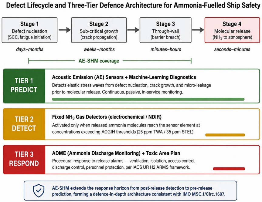
Mapping of the three defence tiers onto the defect lifecycle. AE-SHM (Tier 1) covers Stages 1–3 (nucleation, sub-critical growth, through-wall) on a days-to-months horizon; fixed gas detectors (Tier 2) activate only at Stage 4 (molecular release) on a seconds-to-minutes horizon; ADME and toxic-area procedures (Tier 3) respond after the alarm has been raised
This model is consistent with the goal- and function-based architecture of MSC.1/Circ.1687, which requires layered defence based on risk assessment without prescribing specific sensing technologies for each layer [4]. It is also aligned with the DNV ETO 2026 recommendation that scaled hydrogen and ammonia value chains require an inherently safe design with sensors and barrier management to bridge the confidence gap between pilot and industrial scale [2].
5.2 Sensor Placement Strategy
Effective AE-SHM requires sensor placement that addresses both source coverage and source localisation. For ammonia-fuelled vessels, five system zones warrant systematic instrumentation, summarised schematically in Figure 2:
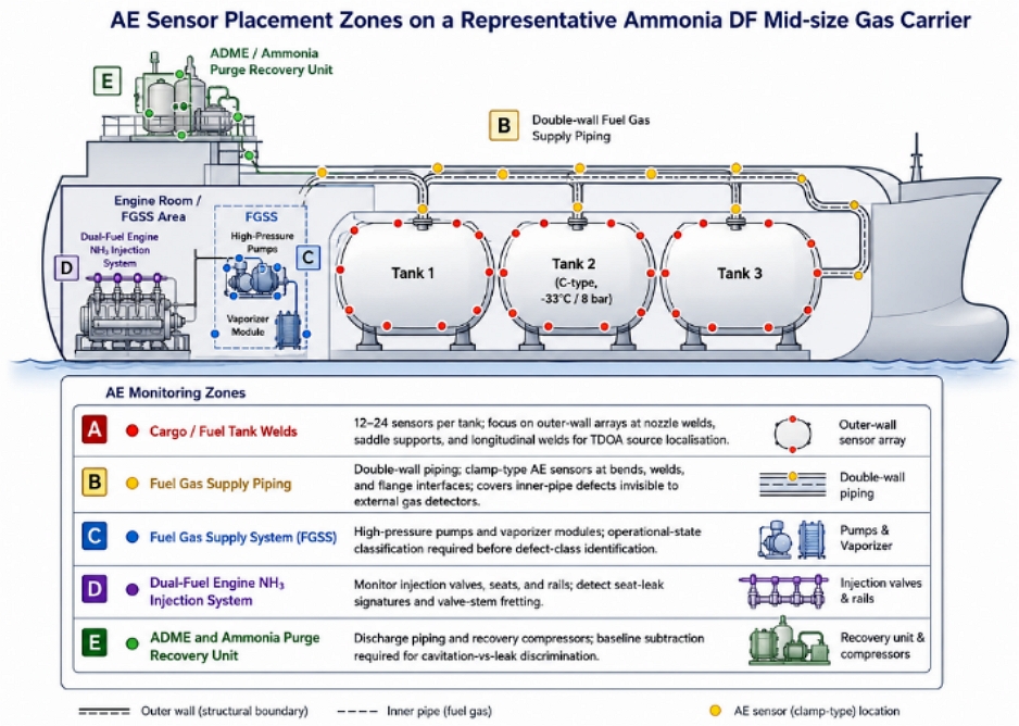
Conceptual placement of AE sensors across the five primary monitoring zones of a representative ammonia DF mid-size gas carrier. Sensor density and type are matched to the dominant failure mechanism of each zone
(a) Fuel storage tanks. C-type independent tanks operating at –33 °C or at approximately 8 bar exhibit the highest consequences of failure. An array of 12–24 broadband AE sensors per tank, distributed at uniform spacing over the outer surface with additional concentration at nozzle welds and saddle support attachments, is recommended.
(b) Fuel gas supply piping. Double-wall piping presents a particular challenge: defects in the inner pipe cannot be detected by external gas sensors until they have penetrated the outer wall. Clamp-type AE sensors mounted on the outer wall provide indirect monitoring of the inner pipe.
(c) Fuel gas supply system (FGSS). High-pressure pumps and vaporiser modules contain dynamic components where defect signatures can be confounded with operational mechanical noise. A two-stage signal-processing approach—operational state classification followed by defect-class identification—is required.
(d) Dual-fuel engine NH₃ injection system. Injection valves, seats, and rails are subject to high-cycle fatigue. AE monitoring focuses on the detection of seat-leak signatures and valve-stem fretting.
(e) ADME and ammonia purge recovery unit. The discharge and recovery systems handle ammonia at conditions that can produce flow-induced cavitation noise easily confused with leakage. Reference operational profiles must be established during commissioning to enable baseline subtraction.
5.3 Edge-Cloud Hybrid Signal-Processing Architecture
The data rate of an AE channel sampled at 1 MS/s with 24-bit resolution is approximately 3 MB/s per channel. A ship-wide installation of 100 channels would therefore produce on the order of 300 MB/s of raw data, exceeding both maritime communication bandwidth and the practical storage budget. A four-level hierarchical processing architecture is proposed (Figure 3):
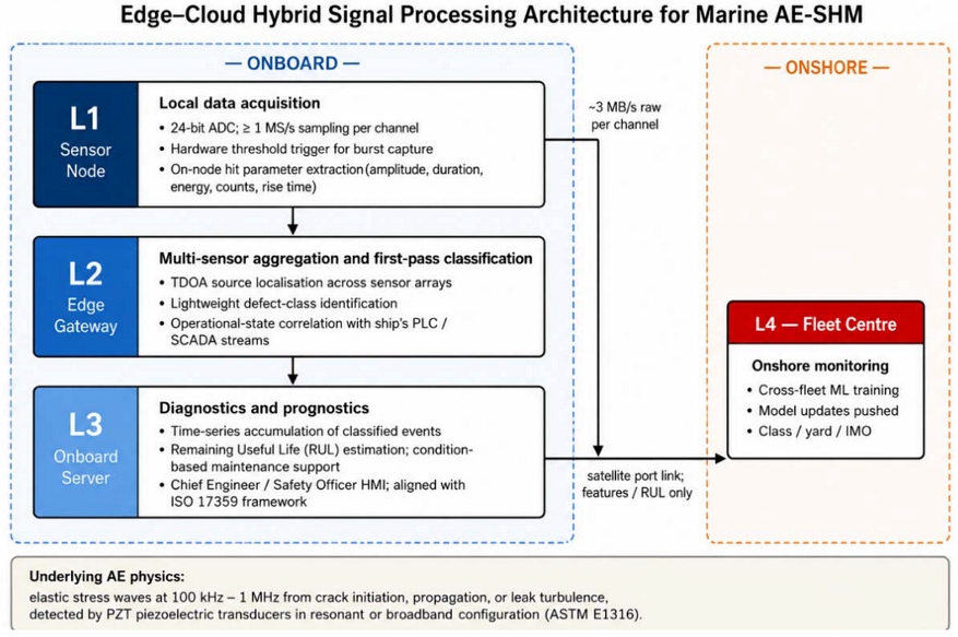
Four-level edge-cloud hybrid signal-processing architecture for marine AE-SHM, showing on-board (L1–L3) and onshore (L4) functional layers with associated data rates. Only classified hit data and prognostic outputs traverse the ship-to-shore link, addressing both bandwidth and cybersecurity constraints
Level 1 — Sensor node. Local 24-bit analogue-to-digital conversion at ≥1 MS/s, hardware threshold trigger, and on-node extraction of hit-based parameters (amplitude, duration, energy, counts, rise time).
Level 2 — Edge gateway. Aggregation of hit data from multiple sensor nodes, source localisation via TDOA, first-pass defect classification using lightweight models, and operational-state correlation with the ship's PLC/SCADA stream.
Level 3 — Onboard server. Time-series accumulation of classified defect events, remaining useful life (RUL) estimation, and condition-based maintenance decision support.
Level 4 — Onshore fleet monitoring centre. Cross-fleet model training, anomaly detection at the fleet scale, and model updates pushed to ships. The hierarchical structure is consistent with the general framework for machinery condition monitoring set out in ISO 17359 [14] and the data-interpretation guidance in ISO 13379-1 [15].
5.4 Machine Learning for Defect Classification and Prognostics
AE signals are noisy in operational environments, and threshold-based classification produces high false-alarm rates. A dual algorithm structure is recommended: first, unsupervised anomaly detection (e.g., autoencoder or one-class support vector machine) to characterise the normal-operation hit-parameter distribution and flag deviations; second, supervised classification (e.g., convolutional neural network on hit waveforms or gradient boosting on hit features) to identify defect classes among flagged events; finally, sequence models (e.g., long short-term memory networks) to extrapolate the accumulated damage indicator toward RUL. The dominant practical obstacle is the absence of a labelled NH₃-AE dataset from commercial marine operation; the assembly of such a dataset is a Stage 1 deliverable in the pathway proposed in Section 6.
6. Regulatory Framework and an Evidence-Gated Qualification Pathway
6.1 MSC.1/Circ.1687: A goal-based window for AE-SHM
MSC.1/Circ.1687 was approved at MSC 109 in December 2024 and circulated by the IMO Secretariat on 26 February 2025 [4]. The Guidelines adopt a goal- and function-based regulatory architecture, with the stated intention that operational experience will inform their future development. Three features of the Guidelines may provide a regulatory basis for considering candidate measures such as AE-SHM: (i) the requirement that the level of safety and reliability be at least equivalent to comparable conventional oil-fuelled installations, which, given the QRA evidence for elevated ammonia risk [6], may motivate consideration of additional risk-mitigation measures; (ii) the explicit allowance of alternative design paths whereby arrangements different from those specified in the Guidelines may be approved on the basis of demonstrated equivalent safety; and (iii) a holistic risk-assessment requirement that may be more readily satisfied by a defence architecture covering the full defect lifecycle rather than the release stage alone.
6.2 Class Society Activity
The classification societies, acting through the International Association of Classification Societies (IACS), have begun translating the IMO Interim Guidelines into more specific technical provisions. IACS originally adopted UR H1 but withdrew it in late 2024 ahead of its scheduled 1 January 2025 implementation. In January 2026, IACS subsequently published UR H2, titled "Design, Construction and Testing of Ammonia Release Mitigation System (ARMS) in Ammonia Fuelled Vessels," for uniform implementation on ships contracted for construction on or after 1 July 2027 [22]. In parallel, IACS issued UR M78 Rev.4 in January 2026, which formally brings anhydrous ammonia within the scope of safety rules for reciprocating internal combustion engines, for application to engines with type approval applications dated on or after 1 July 2027 [23]. AE-SHM, as proposed here, occupies the predictive layer that neither UR H2 (which addresses release-mitigation systems) nor UR M78 (which addresses engine safety) presently covers.
6.3 An Evidence-Gated Technology-Qualification Pathway
The pathway proposed here is deliberately evidence-gated rather than time-boxed. It describes the technical and evidentiary conditions under which AE-SHM could progress from voluntary pilot deployment toward consideration by class societies and, potentially, by the IMO. Progression between stages is conditional on satisfying the entry criteria of the next stage; no calendar dates are prescribed. Normative language ("should", "shall") is avoided throughout: the pathway does not assume, predict, or advocate any particular class or IMO outcome, and any normative force would derive solely from an instrument actually adopted through the applicable regulatory process. Four stages are summarised in Table 4 and depicted in Figure 4.
Four-stage evidence-gated technology-qualification pathway for AE-SHM. Progression between stages is conditional on the exit gate of the previous stage being satisfied; no calendar dates are prescribed and no particular regulatory outcome is assumed
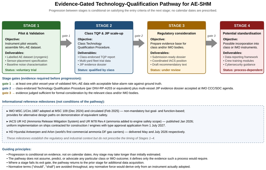
Evidence-gated technology-qualification pathway for AE-SHM. Progression between stages is conditional on satisfying the entry criteria of the next stage; no calendar dates are prescribed and no particular class or IMO outcome is assumed. Reference milestones (IMO MSC.1/Circ.1687, IACS UR H2 and UR M78 Rev.4, and the Antwerpen/Arlon deliveries) are shown for context but do not condition the pathway
A Joint Industry Project (JIP) is proposed as the governance mechanism for Stages 1 and 2. Such a JIP could assemble shipbuilders (HD Hyundai, Samsung Heavy Industries, Hanwha Ocean), shipowners, sensor and signal-processing suppliers, classification societies (Korean Register together with DNV, ABS, and Lloyd's Register), and academic institutions, with principal deliverables aligned to the Stage 1 and Stage 2 exit gates of Table 4. This structure is analogous to the DNV–TotalEnergies–Samsung Heavy Industries JIP on ammonia-ready VLCC design [24]. The pathway does not require any particular JIP membership or timing; the JIP structure is offered as one credible mechanism through which the required evidence could be assembled.
7. Discussion
7.1 Technology readiness assessment
The technology readiness of AE-SHM for ammonia-fuelled ships is heterogeneous across the constituent technologies of the framework proposed in Section 5. Figure 5 presents a bar-chart assessment of five constituent elements against the ISO 16290 TRL scale [28]; the assessment method and the basis of each score are also summarised in the figure. The five TRL ranges in Figure 5 are, in the same order used throughout this review: (i) AE for static pressure vessels, TRL 8–9, supported by codification in ASME BPVC Section V Articles 12 and 13 [11][12] and by long-standing commercial deployment in the power and process industries; (ii) AE for onshore pipeline leak detection, TRL 7–8, supported by operational systems in oil-and-gas transmission and by case-study literature; (iii) AE for cryogenic ammonia service, TRL 5–6, supported by laboratory validation and analogue LNG pilot data but with no published in-service marine NH₃ dataset at commercial scale; (iv) AE integrated with machine-learning prognostics, TRL 4–5, supported by peer-reviewed proof-of-concept studies but with no marine-qualified prognostic model and no labelled NH₃-AE dataset in the public domain; and (v) full onboard AE-SHM integration—including CMS interface, human-machine interface, cybersecurity, and human-factors validation—TRL 3–4, supported by conceptual architecture only. The lower bound of each range is what the authors judge is supportable from present evidence; the upper bound reflects the highest TRL demonstrated in an analogue application. The scores are intentionally conservative. Under the pathway of Section 6, Stage 1 corresponds to raising element (iii) toward TRL 6 with in-service data; Stage 2 corresponds to raising elements (iv) and (v) toward TRL 6–7 through class-endorsed qualification. The scores in Figure 5, the ranges cited in this paragraph, and the pathway stages of Table 4 are intended to be internally consistent.
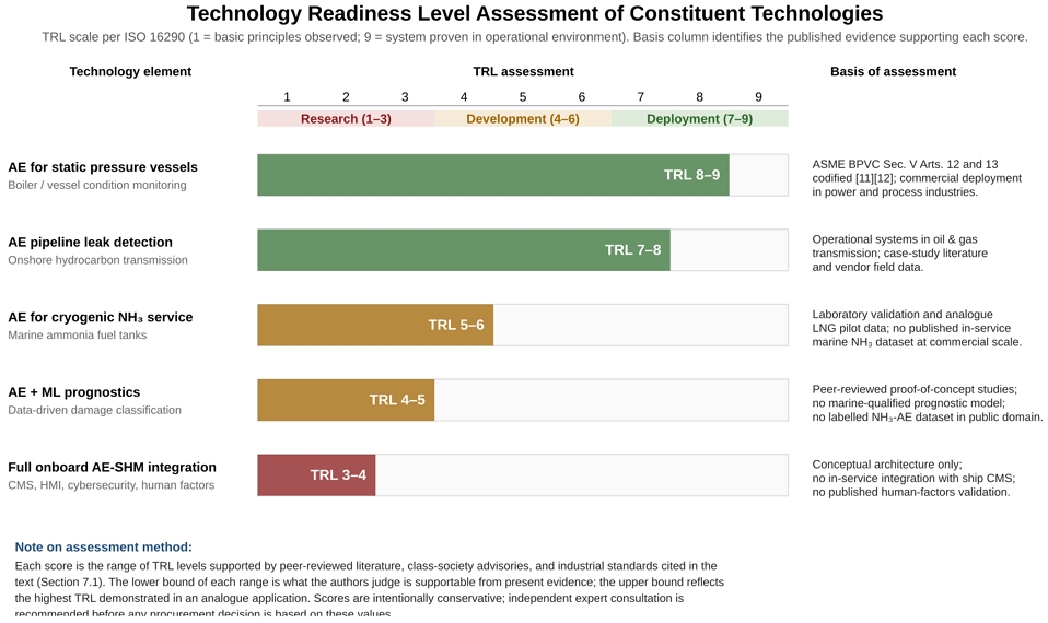
Technology Readiness Level assessment of the constituent technologies of the proposed AE-SHM framework, per ISO 16290. Each score is the range of TRL levels supported by the peer-reviewed literature, class-society advisories, and industrial standards cited in the text. The rightmost column identifies the basis of each score, addressing prior reviewer concerns that the TRL basis was not made explicit
7.2 Open Research Questions
Several substantive research questions remain. First, the spectral and temporal signatures of NH₃-SCC under marine load spectra are not well characterised, and dedicated coupon and component testing programmes are required. Second, the influence of vibration, cavitation, and electromagnetic interference on AE signal quality in operational marine environments must be quantified, and corresponding noise-rejection algorithms validated. Third, the human-factors integration of AE-SHM diagnostics into the ship's bridge and engine-room workflow has not been studied. Fourth, the cybersecurity implications of fleet-scale AE data aggregation must be addressed by design rather than retrofit. The absence, at present, of any operational NH₃-AE dataset from a commercial ammonia-fuelled vessel is the single most binding constraint on further progress.
7.3 Strategic Implications for the Republic of Korea
The Republic of Korea occupies an advantageous position with respect to ammonia-fuelled ship standards. It is simultaneously one of the world's leading builders of ammonia-fuelled vessels and a country whose long-term hydrogen demand is projected to grow substantially. According to the DNV Energy Transition Outlook 2026, South Korea's Contract-for-Difference framework targets in the order of tens of Mt/yr of hydrogen demand by 2050, with a large majority expected to be supplied through imports [2]; this is broadly consistent with the direction of the national Hydrogen Economy Roadmap and its successor implementation plans [25][26]. The convergence of construction leadership, import dependence, and the maturing global decarbonisation policy environment—including the IMO Net-Zero Framework currently under development [19]—provides both the technical capability and the strategic motivation to contribute to international safety standardisation, provided that such contribution is grounded in the evidence identified in the pathway of Section 6.
8. Conclusions
This review has examined the safety architecture of ammonia-fuelled ships at the moment of their transition from prototype to commercial fleet. The principal findings are as follows. (1) Current monitoring is fundamentally reactive, activating only after molecular release. (2) Ammonia-specific failure mechanisms progress through three pre-release stages during which earlier intervention may be possible; these mechanisms operate within a codified prevention envelope (IGC Code Regulation 17.12; IACS UR H2 §3.1.5; PWHT and hardness controls). (3) Acoustic emission sensing offers a technically credible predictive complement to reactive monitoring, subject to the TRL limitations quantified in Section 7.1. (4) The goal- and function-based architecture of IMO MSC.1/Circ.1687 explicitly provides for alternative design paths, allowing AE-SHM to be considered as a demonstrated equivalent measure. (5) A four-stage evidence-gated technology-qualification pathway, in which progression is conditional on evidence rather than on calendar dates, provides a structured, non-prescriptive framework for advancing AE-SHM through class-society qualification and, if the evidence supports it, toward possible consideration by class and IMO bodies. The Republic of Korea is well positioned to contribute to the pathway.
Acknowledgments
The author acknowledges discussions with members of the Korea Marine Plant Service Industry Association regarding regulatory pathways under IMO MSC.1/Circ.1687, and thanks the anonymous reviewers of the previous revisions for their detailed and constructive comments.
Author Contributions
Conceptualization, Youngcheon Jang; Methodology, Youngcheon Jang; Investigation, Youngcheon Jang and Hyewon Kim; Resources, Hyewon Kim; Writing—Original Draft Preparation, Youngcheon Jang; Writing—Review & Editing, Youngcheon Jang and Hyewon Kim; Visualization, Youngcheon Jang and Hyewon Kim; Supervision, Youngcheon Jang; Project Administration, Youngcheon Jang.
Conflicts of Interest
The author declares that he serves as Chief Executive Officer of SENSOLtechnology, Inc., a company developing acoustic emission sensing solutions for the marine and offshore sectors. The technical and regulatory recommendations in this review are presented on the basis of the published literature and the publicly available regulatory documents cited herein.
References
- International Energy Agency, Net Zero Roadmap: A Global Pathway to Keep the 1.5 °C Goal in Reach — 2023 Update, Paris, France: IEA, 2023.
- DNV, Energy Transition Outlook 2026 — Hydrogen to 2060: From Pilots to Scale for Renewable and Low-Carbon Hydrogen and Synthetic Fuels, Høvik, Norway: Det Norske Veritas, 2026.
- HD Hyundai Heavy Industries, "Naming ceremony of the world's first ammonia dual-fuel mid-size gas carriers Antwerpen and Arlon at Ulsan Shipyard," Press release, April 9, 2026.
- International Maritime Organization, "Interim guidelines for the safety of ships using ammonia as fuel," MSC.1/Circ.1687, London, UK: IMO Secretariat, February 26, 2025.
- BIMCO, "IMO interim guidelines for the safety of ships using ammonia as fuel: Industry overview," The Baltic and International Maritime Council, Bagsværd, Denmark, 2025.
-
K. -T. Moon, P. Davies, L. Wright, and S. -J. Choi, “DeRiskbeta: Comparative quantitative risk assessment (QRA) of fuel oil, LNG, methanol, and ammonia on a 15,000 TEU containership,” Journal of Advanced Marine Engineering and Technology, vol. 49, no. 1, pp. 42-61, 2025.
[https://doi.org/10.5916/jamet.2025.49.1.42]

-
I. -S. Kim, B. -U. Jeong, M. -K. Song, and D. Nam, “Determination of bunkering safety zones for ammonia-fueled ship,” Journal of Advanced Marine Engineering and Technology, vol. 46, no. 5, pp. 261-269, 2022.
[https://doi.org/10.5916/jamet.2022.46.5.261]
-
D. -S. Gu, J. -M. Lee, J. -H. Lee, J. -M. Ha, and B. -K. Choi, “Comparison of Hilbert and Hilbert-Huang transform for the early fault detection by using acoustic emission signal," Journal of the Korean Society of Marine Engineering, vol. 36, no. 2, 2012.
[https://doi.org/10.5916/jkosme.2012.36.2.258]
-
F. Yanagimoto, K. Shiotani, Y. Sakakibara, Y. Watanabe, and E. Tada, “Stress corrosion cracking of steels in liquid ammonia: A comprehensive literature review,” International Journal of Hydrogen Energy, vol. 120, pp. 89-100, 2025.
[https://doi.org/10.1016/j.ijhydene.2025.03.280]
- ASTM International, Standard Terminology for Nondestructive Examinations, ASTM E1316-23, West Conshohocken, PA, USA: ASTM International, 2023.
- American Society of Mechanical Engineers, Boiler and Pressure Vessel Code, Section V — Nondestructive Examination, Article 12: Acoustic Emission Examination of Metallic Vessels During Pressure Testing, New York, NY, USA: ASME.
- American Society of Mechanical Engineers, Boiler and Pressure Vessel Code, Section V — Nondestructive Examination, Article 13: Continuous Acoustic Emission Monitoring, New York, NY, USA: ASME.
-
W. Sikorski, “Development of acoustic emission sensor optimized for partial discharge monitoring in power transformers,” Sensors, vol. 19, no. 8, art. 1865, 2019.
[https://doi.org/10.3390/s19081865]
- International Organization for Standardization, Condition Monitoring and Diagnostics of Machines — General Guidelines, ISO 17359:2018, Geneva, Switzerland: ISO, 2018.
- International Organization for Standardization, Condition Monitoring and Diagnostics of Machines — Data Interpretation and Diagnostics Techniques — Part 1: General Guidelines, ISO 13379-1:2012, Geneva, Switzerland: ISO, 2012.
- American Bureau of Shipping, Ammonia as Marine Fuel — Technology and Safety Advisory, Houston, TX, USA: ABS, 2024.
- DNV, Ammonia as a Marine Fuel — Safety Handbook, 2nd ed., Høvik, Norway: Det Norske Veritas, 2024.
- International Maritime Organization, "Report of the Maritime Safety Committee on its 109th session," MSC 109/20, London, UK: IMO, December 2024.
- International Maritime Organization, "Net-zero framework for international shipping," Marine Environment Protection Committee, London, UK: IMO, 2025 (under adoption).
- American Conference of Governmental Industrial Hygienists, TLVs and BEIs: Threshold Limit Values for Chemical Substances and Physical Agents and Biological Exposure Indices, Cincinnati, OH, USA: ACGIH, 2024.
- U.S. National Institute for Occupational Safety and Health, NIOSH Pocket Guide to Chemical Hazards, DHHS (NIOSH) Publication No. 2005-149, Cincinnati, OH, USA: NIOSH, September 2007.
- International Association of Classification Societies, Unified Requirement UR H2 — Design, Construction and Testing of Ammonia Release Mitigation System (ARMS) in Ammonia Fuelled Vessels, IACS Req. 2026, London, UK: IACS, January 2026. (Applied to ships contracted for construction on or after 1 July 2027. Section 3.1.5 requires materials in anhydrous ammonia systems to comply with Regulation 17.12 of the IGC Code.)
- International Association of Classification Societies, Unified Requirement UR M78 (Rev.4) — Safety Aspects of Internal Combustion Engines, London, UK: IACS, January 2026. (Applied to engines with type approval applications dated on or after 1 July 2027.)
- DNV, TotalEnergies, and Samsung Heavy Industries, Ammonia-Ready VLCC Design Joint Industry Project — Findings, DNV Maritime Impact, 2022.
- International Energy Agency, Global Hydrogen Review 2025, Paris, France: IEA Publications, 2025.
- Ministry of Trade, Industry and Energy of the Republic of Korea, Hydrogen Economy Revitalization Roadmap, Sejong, Republic of Korea: MOTIE, January 2019.
- International Maritime Organization, International Code for the Construction and Equipment of Ships Carrying Liquefied Gases in Bulk (IGC Code), London, UK: IMO, as amended. (Regulation 17.12 addresses materials for anhydrous ammonia service.)
- International Organization for Standardization, Space Systems — Definition of the Technology Readiness Levels (TRLs) and Their Criteria of Assessment, ISO 16290:2013, Geneva, Switzerland: ISO, 2013.