
Design of a printed dipole array for radar and satellite communication

Copyright © The Korean Society of Marine Engineering
This is an Open Access article distributed under the terms of the Creative Commons Attribution Non-Commercial License (http://creativecommons.org/licenses/by-nc/3.0), which permits unrestricted non-commercial use, distribution, and reproduction in any medium, provided the original work is properly cited.
Abstract
This paper proposes a compact, printed Log-Periodic Dipole Array (LPDA) to address the demand for high-performance wideband antennas in Ku-band Low Earth Orbit (LEO) satellite and radar applications. Conventional LPDAs often suffer from radiation distortion caused by front-feed cable obstructions. To overcome these issues, we introduce a novel rear-feed structure using a partial ground. This asymmetric design inherently acts as a planar balun for stable balanced-mode operation while effectively eliminating cable interference. By optimizing the antenna to just four dipole elements, it achieves significant miniaturization and consistent beam stability without sacrificing broadband capabilities. Experimental measurements of reflection coefficients and antenna gain validate the design. Furthermore, the 2×8 array configuration demonstrates stable beam-steering, confirming the antenna's practical suitability for highly integrated aerospace platforms.
Keywords:
Antennas, Broadband antenna, Log-periodic dipole array antenna, LDPA, Ku band radar, Satellite communication1. Introduction
Recently, Low Earth Orbit (LEO) satellite constellations have emerged as a pivotal infrastructure for establishing a seamless global network. Unlike traditional terrestrial networks, LEO satellite systems provide essential connectivity across maritime and aerospace environments, where ground-based stations are inaccessible. In particular, such infrastructure provides a stable operational foundation for unmanned aerial vehicles (UAVs), maritime vessels, and long-range drones that should operate reliably beyond the reach of conventional networks [1,2]. Despite the strategic importance of these satellite links, current hardware infrastructure faces significant technical hurdles. Numerous conventional communication antennas are not optimized for the high-frequency requirements of modern satellite services and high-resolution radar systems. Specifically, there is a critical shortage of compact, high-performance antenna technologies designed for the Ku-band low earth orbit (LEO) satellite communications (typically 12~18 GHz), which is vital for high-capacity satellite data transmission and precision radar applications [3-5]. To address the requirements of such a multifunctional environment, two primary hardware strategies can be considered.
The first involves installing multiple dedicated antennas for each specific frequency band, which consequently increases the system’s weight, cost, and aerodynamic drag. A more efficient approach is to employ a single wideband antenna capable of covering the entire required spectrum. Developing a system with a unified wideband antenna facilitates miniaturization, simplifies maintenance, and enables the implementation of multiple functions, such as simultaneous communication and sensing within a single hardware platform [6].
The Log-Periodic Dipole Array (LPDA) has been a suitable candidate due to its frequency-independent properties. Nevertheless, conventional LPDA designs often suffer from radiation pattern distortion because the feed point is typically located on the radiating side of the antenna, physically obstructing the main radiation lobe [7].
While previous research has attempted to mitigate these issues by extending feed lines to the rear section of the antenna, such configurations often lead to excessive manufacturing complexity and structural instability when scaling from a single element to an array [8, 9].
In this paper, we propose a compact printed LPDA with an optimized four-element dipole to achieve both miniaturization and broadband performance for radar and satellite applications. To resolve the physical obstruction inherent in conventional feeding structures, the proposed antenna adopts a novel LPDA feed design utilizing a partial ground. Since the partial grounding structure is positioned at the rear of the radiator, it eliminates the cable interference problems typical of conventional LPDAs, where the feed cable is connected to the front. Moreover, the asymmetric configuration of the antenna, resulting from the partial ground, inherently functions as a planar balun, ensuring stable balanced-mode operation. The number of dipole elements in the proposed LPDA has been minimized to the threshold required to guarantee the target bandwidth. This configuration further prevents radiation pattern distortion, ensuring consistent beam stability across the entire operating range. Furthermore, by avoiding an unnecessary increase in the physical size of the antenna, the design offers superior integration capabilities for satellite and radar platforms. To verify the feasibility of the design, the antenna gain and reflection coefficient are measured, confirming stable performance across the target frequency band. To evaluate the practical utility of the antenna, the proposed antenna is arranged in a 2×8 array configuration, verifying its beam-steering performance. The proposed antenna demonstrates stable beam steering within the target range, confirming its suitability for actual satellite and radar systems.
2. Design and Fabrication of Proposed Antenna
Figure 1 shows the configuration of the proposed broadband printed dipole antenna array. The proposed antenna structure consists of a partial ground and printed dipole elements to determine the operating frequency and bandwidth. The antenna is fabricated on a Duroid substrate with a relative permittivity of 2.1 and a thickness of 1 mm. The horizontal and vertical dimensions of the substrate are defined as gx and gy, respectively. The parameters of the dipole array elements are described by l for the dipole length, s for the dipole thickness, and s for the spacing between the adjacent dipoles. In addition, fw and fl denote the designed parameters related to the partial ground, where fw is the width of the front side feeding line and fl is the length of the backside partial ground. The length of the front side feeding line is equal to fl. The designed parameters are carefully optimized using CST simulation to derive the broadband characteristics, and the optimized values are listed in Table 1.
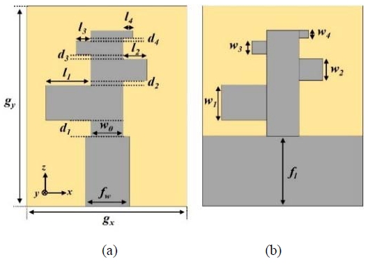
Proposed single element antenna structure: (a) Top view; (b) Bottom view

Design parameters of proposed antenna
Figure 2 presents a photograph of the fabricated antenna. The proposed antenna incorporates a partial ground in its feeding structure to prevent the radiation pattern distortion and to maintain structural stability during array expansion. The copper layers are printed on both sides of a 1mm thick Duroid substrate with a length of 21.5 mm using an etching process. Each copper layer consists of a partial ground and a dipole array.
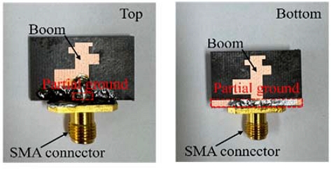
Photograph of the proposed antenna
Figure 3 represents the reflection coefficient of the proposed antenna. The antenna covers the operating frequency range from 8 to 18 GHz. The simulated and measured results indicate that the reflection coefficient remains below -10 dB throughout the operating band with the impedance matching. The simulated and measured boresight gain characteristics of the proposed antenna are shown in Figure 4. The antenna achieves a maximum gain of 6.8 dBi at 15 GHz and maintains an average gain of 5.3 dBi across the operating frequency range. The simulated and measured results show slight discrepancies, and differences are primarily attributed to unavoidable fabrication tolerances, such as minor variations in dielectric constant of the substrate, slight over/under-etching during the PCB manufacturing process, and parasitic effects from the SMA connector soldering. Additionally, measurement uncertainties, including cable losses and minor misalignment during the anechoic chamber measurements, contributed to the discrepancies.
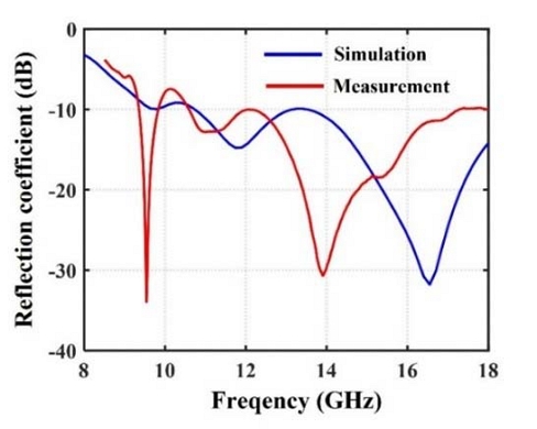
Reflection coefficient of the proposed antenna
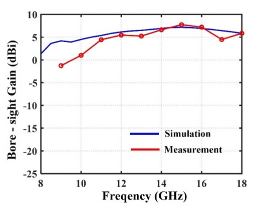
Bore-sight gain of the proposed antenna
Figure 5 shows the E-field distribution of the proposed antenna to observe the currents flowing on the top and bottom arms, which are equal in magnitude but opposite in phase (180° out-of-phase), effectively demonstrating the unbalanced-to-balanced conversion by the planar balun with partial ground.
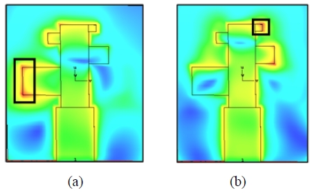
E-field distribution of the proposed antenna. (a) 9.5 GHz, (b) 17 GHz
3. Array Antenna Results
Figure 6 presents the configuration of the proposed antenna when extended to a 16-element array. The array antenna performance is evaluated to verify its suitability for radar and satellite communication applications. Figure 6 shows the beam-steering performances of the array antenna for scan angles ranging from 0° to 30° in 5° increments at 12 GHz. The results show that the main beam can be steered to the desired direction without the distortion. In particular, the proposed array antenna achieves a gain of 17.5 dBi with a 3 dB beamwidth of 10° at a steering angle of 30°, demonstrating stable beam-steering performance over the targeted scan range.
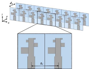
Proposed 2×8 array antenna structure
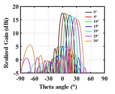
Simulated beam steering of array antenna
4. Conclusion
In this paper, we presented a compact, wideband printed Log-Periodic Dipole Array (LPDA) optimized for Ku-band LEO satellite communications and precision radar applications. To overcome the critical limitations of conventional LPDAs specifically, radiation pattern distortion and physical obstruction caused by front-feed cables, the partial ground was adopted to obtain the rear-feeding structure with the limited number of dipole elements in the proposed antenna. The feasibility and robustness of the proposed single-element design were experimentally validated through the measurements, such as the reflection coefficient and antenna gain. The results demonstrated that consistent and stable performance across the target frequency band (8 GHz ~ 18 GHz).
To verify the practical utility and scalability of the design for real-world scenarios, the proposed antenna was expanded into a 2×8 array configuration. The array antenna exhibited reliable beam-steering capabilities over a steering range of ± 30°, maintaining stable radiation characteristics. It is expected to be an excellent candidate for emerging multifunctional aerospace platforms, including UAVs, maritime vessels, and LEO satellites, where lightweight, compact, and highly reliable communication systems are essential. In future research, the proposed antenna structure should consider to mutual coupling mitigation techniques, such as employing decoupling networks, defected ground structures or optimized indirect coupling schemes, to further enhance the performance of the proposed array antenna.
Acknowledgments
Following are results of a study on the “Glocal University Project Group in Gyeongkuk National University” Project, supported by the Ministry of Education and National Research Foundation of Korea.
Author Contributions
Conceptualization, S. Ahn and S. Yoo; Methodology, S. Yoo; Software, S. Yoo; Validation, S. Ahn, D. Jang and S. Yoo; Formal Analysis, S. Ahn and D. Jang; Investigation, S. Ahn; Resources, S. Ahn; Data Curation, S. Yoo; Writing—Original Draft Preparation, S. Ahn and D. Jang; Writing—Review & Editing, D. Jang and S. Yoo; Visualization, S. Ahn; Supervision, S. Yoo; Project Administration, S. Yoo; Funding Acquisition, S. Ahn.
References
-
M. Li, Y. Su, Y. Yao, W. Zhang, X. Lin, and Y. Fan, “A broadband dual-polarized C-/Ku-band shared aperture antenna array for satellite communications,” IEEE Transactions on Antennas and Propagation, vol. 72, no. 11, pp. 8840-8845, Nov, 2024.
[https://doi.org/10.1109/TAP.2024.3439827]

-
X. Teng, Y. Hou, C. Guo, S. Wang, and K. Ma, “Broadband low-profile multifunction dual-polarized dipole antenna and array for 5G and WiFi application,” IEEE Antennas and Wireless Propagation Letters, vol. 23, no. 6, pp. 1849-1853, June, 2024.
[https://doi.org/10.1109/LAWP.2024.3371495]
-
J. Park, C. Im, and H. Choo, “Design of a koch-curved LPDA antenna with optimized beamwidth to improve the aperture efficiency of reflector antennas,” IEEE Access, vol. 13, pp. 106747-106758, 2025.
[https://doi.org/10.1109/ACCESS.2025.3581215]
-
D. E. Anagnostou, J. Papapolymerou, M. M. Tentzeris, and C. G. Christodoulou, “A Printed Log-Periodic Koch-Dipole Array (LPKDA),” IEEE Antennas and Wireless Propagation Letters, vol. 7, pp. 456-460, 2008.
[https://doi.org/10.1109/LAWP.2008.2001765]
-
G. Zhai, Y. Cheng, Q. Yin, L. Chiu, S. Zhu, and J. Gao, “Super high gain substrate integrated clamped-mode printed log-periodic dipole array antenna,” IEEE Transactions on Antennas and Propagation, vol. 61, no. 6, pp. 3009-3016, June, 2013.
[https://doi.org/10.1109/TAP.2013.2246853]
-
Y. Chen, et al., “Landstorfer printed log-periodic dipole array antenna with enhanced stable high gain for 5G communication,” IEEE Transactions on Antennas and Propagation, vol. 69, no. 12, pp. 8407-8414, Dec, 2021.
[https://doi.org/10.1109/TAP.2021.3090079]
-
G. Zhai, Y. Cheng, Q. Yin, S. Zhu, and J. Gao, “Gain enhancement of printed log-periodic dipole array antenna using director cell,” IEEE Transactions on Antennas and Propagation, vol. 62, no. 11, pp. 5915-5919, Nov, 2014.
[https://doi.org/10.1109/TAP.2014.2355851]
-
X. Wei, J. Liu, and Y. Long, “Printed log-periodic monopole array antenna with a simple feeding structure,” IEEE Antennas and Wireless Propagation Letters, vol. 17, no. 1, pp. 58-61, Jan, 2018.
[https://doi.org/10.1109/LAWP.2017.2773606]
-
Z. Hu, S. Cao, M. Liu, C. Hua, and Z. Chen, “A planar low-profile log-periodic array based on cavity-backed slot,” IEEE Antennas and Wireless Propagation Letters, vol. 18, no. 10, pp. 1966-1970, Oct. 2019.
[https://doi.org/10.1109/LAWP.2019.2933981]