
Design and development of a CNC-based automated multi-pipetting workstation incorporating mechanical syringe calibration and vision-based position correction

Copyright © The Korean Society of Marine Engineering
This is an Open Access article distributed under the terms of the Creative Commons Attribution Non-Commercial License (http://creativecommons.org/licenses/by-nc/3.0), which permits unrestricted non-commercial use, distribution, and reproduction in any medium, provided the original work is properly cited.
Abstract
Emerging infectious diseases have highlighted the need for affordable laboratory automation to support high-throughput diagnostics. This study presents an enhanced low-cost automated multi-pipetting workstation based on a CNC three-axis motion platform. The system integrates a four-syringe dispensing module with individual mechanical calibration, automated plate dispensing and stacking, automated pipette-tip attachment and ejection, and a vision-based real-time position correction algorithm. A graphical user interface enables fully autonomous operation, including plate supply, pipette-tip handling, aspiration, dispensing, and plate collection. Experimental results demonstrated X–Y positioning accuracy within ±0.5 mm at travel speeds up to 75 mm/s. After syringe calibration, all four syringes consistently dispensed the target mass of 1.00 g within ±0.10 g. The vision-based correction algorithm achieved a 100% pipette-tip-to-well alignment success rate during repetitive operation. The workstation processed approximately 19 well plates per hour, increasing throughput by 1.9 times while reducing operator intervention compared with manual pipetting. These results demonstrate that the proposed system provides a practical and cost-effective laboratory automation solution for small- and medium-sized laboratories.
Keywords:
Automated multi-pipetting workstation, CNC-based motion platform, Syringe calibration, Vision-based position correction, Low-cost laboratory automation1. Introduction
The global increase in Emerging Infectious Diseases (EIDs), exemplified by the COVID-19 pandemic, has underscored the critical importance of diagnostic systems capable of rapidly and accurately processing large numbers of clinical samples. Since the mid-twentieth century, the frequency of EID outbreaks has steadily increased owing to factors such as climate change, urbanization, global population mobility, and intensified human–animal interactions, all of which have contributed to increasingly complex patterns of disease emergence and transmission [1]-[3]. These trends suggest that future infectious disease outbreaks are likely to recur, highlighting the necessity for scalable diagnostic infrastructures that can rapidly accommodate sudden surges in testing demand.
The COVID-19 pandemic clearly exposed the limitations of existing diagnostic workflows. Among the available diagnostic methods, reverse transcription polymerase chain reaction (RT-PCR) became the standard method for detecting SARS-CoV-2 owing to its high sensitivity and specificity [4]. However, RT-PCR-based diagnostic workflows include multiple sample preparation and liquid-handling steps, such as sample dispensing, reagent mixing, and repetitive pipetting, many of which still rely heavily on manual operation. Therefore, when testing demand increases rapidly, repetitive manual pipetting can become a major bottleneck that limits laboratory throughput and delays result reporting. El Hage et al. [5] reported that personnel-intensive RT-PCR workflows are poorly suited to sudden increases in testing volume. Accordingly, expanding diagnostic capacity requires not only additional laboratory facilities but also automated multi-pipetting and liquid-handling technologies that can automate manual liquid-handling steps while improving throughput and operational efficiency [5]-[7].
These limitations became particularly evident in South Korea during the COVID-19 pandemic. Although RT-PCR testing capacity was rapidly expanded through public health institutions, metropolitan hospitals, and specialized diagnostic laboratories [8]-[10], repeated waves of infection placed substantial operational burdens on clinical laboratories and diagnostic testing facilities [11]-[13]. These circumstances indicate that stable diagnostic capacity depends not only on the number of testing facilities but also on the availability of scalable laboratory automation resources. In particular, regional medical centers and small- to medium-sized laboratories may face greater difficulty in maintaining consistent diagnostic throughput because of limited personnel, financial resources, and automation infrastructure.
To improve the accuracy and efficiency of repetitive liquid-handling tasks, various automated liquid-handling and pipetting platforms have been developed [14]-[16]. Representative commercial systems, including the Eppendorf epMotion 5075 LH, epMotion 96 Flex, and Tecan Freedom EVO 200, provide highly accurate and reproducible liquid dispensing through precision motion control and sophisticated automation software. These systems have become widely adopted in large-scale diagnostic and research laboratories because of their high throughput and excellent dispensing performance. Nevertheless, their substantial acquisition and maintenance costs considerably limit their accessibility, particularly for laboratories with constrained financial resources
To clarify the low-cost nature of the proposed workstation, the present study considered a system-level cost comparison based on an approximate target supply price rather than a detailed component-level bill of materials, because detailed component costs depend on procurement conditions, fabrication quantity, and local availability. The proposed CNC-based automated multi-pipetting workstation was designed with an estimated target supply price of approximately KRW 3.0 million. In contrast, publicly available pricing information and used/refurbished market listings indicate that representative commercial automated liquid-handling platforms generally cost at least several tens of thousands of U.S. dollars, depending on configuration and condition. Therefore, although the comparison is approximate and configuration-dependent, the proposed workstation could be supplied at a substantially lower cost than representative commercial systems, making it a more accessible alternative for small- and medium-sized laboratories.
Manual pipetting, however, suffers from several inherent limitations. Repetitive pipetting requires continuous control of aspiration speed, dispensing pressure, and pipetting angle, thereby imposing significant physical stress on laboratory personnel and increasing the risk of work-related musculoskeletal disorders [17]. Furthermore, operator fatigue accumulated during repetitive tasks may reduce concentration and increase dispensing variability. Because RT-PCR analysis requires high quantitative precision, even minor variations in dispensing volume may influence reagent concentration and downstream analytical reliability. Such variability is further exacerbated by differences in operator experience, pipetting technique, and individual handling characteristics [18]-[20]. Consequently, manual pipetting inherently limits both the reproducibility and scalability of high-throughput diagnostic workflows.
These challenges became particularly pronounced during the pandemic, when many laboratories experienced excessive workloads, extended working hours, and delayed diagnostic processing [10][13]. Such operational burdens were especially severe in regional hospitals and private diagnostic laboratories, where limited personnel, financial resources, and automation infrastructure restricted testing capacity. These observations highlight the need for a cost-effective automated liquid-handling platform capable of bridging the gap between expensive commercial automation systems and conventional manual pipetting by simultaneously improving dispensing consistency, operational efficiency, and affordability.
To address this need, our research group previously developed a low-cost CNC-based automatic multi-pipette system incorporating a three-axis motion platform and a four-syringe dispensing module [21]. The previous prototype successfully demonstrated basic positioning accuracy and simultaneous aspiration capability using a common plunger-driving mechanism. However, because all syringe plungers were actuated simultaneously without individual mechanical adjustment, differences in effective plunger stroke among the syringes could not be compensated, and the uniformity of the actual dispensed amount was not quantitatively validated. Moreover, the previous prototype required manual intervention for pipette-tip attachment, plate loading, plate positioning, and plate collection, limiting its applicability to fully automated laboratory workflows.
To overcome these limitations, this study presents an improved CNC-based automated multi-pipetting workstation with substantially enhanced functionality and operational autonomy.
A mechanical syringe calibration mechanism was introduced to independently adjust the effective plunger stroke of each syringe, thereby improving dispensing uniformity among the four syringes. Unlike the previous study, which primarily evaluated positioning accuracy and aspiration performance, the present work quantitatively verifies dispensing accuracy through gravimetric measurements of the dispensed mass. Furthermore, the system integrates an automatic plate dispenser and organizer, automated pipette-tip attachment and ejection mechanisms, and a vision-based real-time position correction algorithm to compensate for conveyor-induced plate misalignment during automated operation.
Consequently, the proposed workstation extends the previous CNC-based prototype into a fully integrated laboratory automation platform capable of autonomously performing the entire liquid-handling workflow, including plate supply, pipette-tip attachment, reagent aspiration, dispensing, tip ejection, and plate stacking. The primary objective of this study is to develop a practical, low-cost automated multi-pipetting workstation that enhances dispensing accuracy, operational stability, workflow automation, and practical applicability while maintaining the economic advantages of a CNC-based architecture. The experimental performance of the proposed system is systematically validated through positioning accuracy, dispensing accuracy, throughput, and vision-based position correction experiments, demonstrating its potential as an affordable laboratory automation solution for resource-limited diagnostic environments.
2. System Architecture and Mechanical Design
This section presents the overall architecture, operational framework, and key mechanical enhancements of the proposed automated multi-pipetting workstation in comparison with the previously developed CNC-based prototype [21]. The overall system architecture is first introduced through a comparative analysis with the previous prototype, followed by a description of the automated workflow and control strategy. Subsequently, the design and functionality of the major subsystems are presented, including the CNC motion platform, the multi-pipetting module with an integrated syringe calibration mechanism, the automated pipette-tip attachment and ejection mechanism, the plate handling subsystem, the automatic plate organizer, and the vision-based position correction system.
2.1 Overall System Configuration
Figure 1 compares the overall configurations of the previously developed CNC-based multi-pipetting prototype [21] and the proposed automated multi-pipetting workstation. As shown in Figure 1(a), the previous prototype consisted primarily of a CNC three-axis motion platform and a four-syringe pipetting module. Although the system successfully demonstrated CNC-based positioning and simultaneous multi-syringe liquid handling, several critical procedures, including pipette-tip attachment, well-plate loading, plate positioning, and plate collection, were performed manually. Consequently, continuous operator intervention was required throughout the dispensing process, limiting the level of workflow automation.
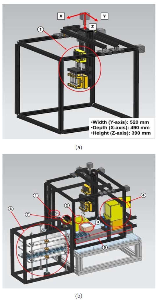
Overall configuration comparison of the CNC-based multi-pipetting systems: (a) previous prototype [21]; (b) present automated workstation with newly integrated subsystems: (1) Pipette-tip ejection unit; (2) Tip rack holder; (3) Sample aspiration unit; (4) Plate dispenser; (5) Conveyor belt; (6) Automatic plate organizer; (7) Camera.
To address these limitations, an enhanced automated multi-pipetting workstation was developed, as illustrated in Figure 1(b). The proposed workstation preserves the fundamental mechanical architecture of the previous prototype, including the CNC three-axis motion platform, X–Y–Z coordinate system, mechanical workspace, and four-syringe pipetting module, while incorporating several additional subsystems to enable fully automated operation. These newly integrated components include an automated pipette-tip ejection unit, a tip-rack holder, a sample aspiration unit, a plate dispenser, a conveyor-based plate transport system, an automatic plate organizer, and a vision-based position correction system. Collectively, these subsystems enable automated pipette-tip attachment and ejection, reagent aspiration, plate supply and transport, plate stacking, and vision-based position correction prior to dispensing.
By integrating these functions into a single platform, the proposed workstation extends the previous CNC-based prototype from a semi-automated liquid-handling device to a fully automated laboratory workstation. As a result, the entire liquid-handling workflow, including plate supply, pipette-tip attachment, reagent aspiration, dispensing, tip ejection, and plate stacking, can be executed autonomously without continuous user intervention, thereby improving operational efficiency, workflow reliability, and overall laboratory productivity.
2.2 System Operation and Control Framework
The overall automated workflow of the proposed multi-pipetting workstation is illustrated in Figure 2. In contrast to the previous prototype, which required manual intervention for pipette-tip handling, plate positioning, and plate collection, the developed system integrates these operations into a fully automated control framework.
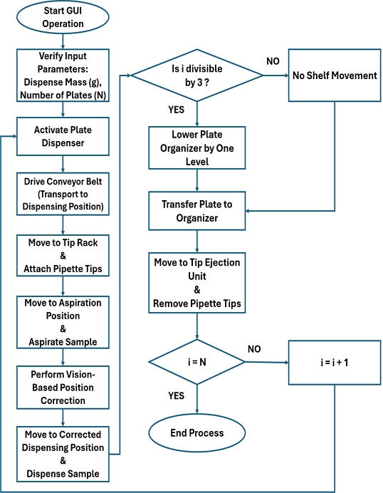
Flowchart of the overall control logic and automated pipetting workflow
The operation begins with user-defined input parameters, including the target dispensing mass and the total number of well plates, through the graphical user interface (GUI). Based on these inputs, the controller actuates the plate dispenser to release a single well plate onto the conveyor system, which subsequently transports the plate to the dispensing station.
Upon arrival at the dispensing station, the CNC-mounted pipetting module automatically performs pipette-tip attachment followed by reagent aspiration. Before dispensing, the vision-based position correction system detects the actual location of the transported well plate and estimates its positional deviation from the reference coordinate. The detected offset is converted into a corrected dispensing coordinate using the predefined compensation model, and the CNC motion platform subsequently relocates the pipetting module to the corrected position to ensure accurate alignment between the pipette tips and the target wells.
Following reagent dispensing, the system updates the internal plate counter (i), which represents the number of processed plates, and determines the storage position within the automatic plate organizer. Because each shelf is designed to accommodate three well plates, the controller uses the remainder of i modulo three to determine whether shelf movement is required. If storage space remains available on the current shelf, the processed plate is transferred directly onto that shelf. Otherwise, the organizer is lowered by one shelf level through the lead-screw mechanism before the subsequent plate is delivered to the next available storage position. After plate transfer, the used pipette tips are automatically removed by the pipette-tip ejection unit, and the entire operating sequence is repeated until all preset well plates have been processed.
By integrating plate supply, pipette-tip attachment, reagent aspiration, vision-based position correction, reagent dispensing, pipette-tip ejection, and automated plate stacking into a unified control framework, the proposed workstation enables continuous and fully autonomous operation. This integrated workflow minimizes operator intervention while improving operational reliability, process repeatability, and throughput, thereby enhancing the suitability of the system for high-throughput laboratory applications.
2.3 Mechanical Subsystems
The CNC motion platform employed in this study was developed based on the platform reported in our previous work [21], while preserving its fundamental three-axis (X–Y–Z) mechanical architecture. To improve the positional repeatability required for fully automated operation, several modifications were introduced.
First, end-stop switches were installed on each axis to establish a repeatable homing procedure, allowing the platform to return consistently to a predefined reference position at the beginning of every operating cycle. Second, microstepping control was implemented for all stepper motors, and the motion resolution of each axis was recalibrated according to its individual transmission characteristics. Stepper motors were selected for the CNC motion platform because they enable repeatable stepwise motion control with a simple and low-cost open-loop control structure. Since the commanded displacement can be controlled by adjusting the number of motor steps and microstepping resolution, stepper motors are suitable for repetitive positioning tasks such as pipette-tip attachment, ejection, and well alignment. In addition, they are readily compatible with CNC-based absolute-coordinate motion control, making them appropriate for a cost-constrained laboratory automation platform. The same stepper motor-based motion hardware reported in Ref. [21] was employed in the present workstation. The detailed motor specifications, including a step angle of 1.8°, rated voltage of 3.6 V DC, rated current of 1.5 A, and motor length of 38 mm, are provided in Ref. [21].
These modifications significantly increased the positioning resolution compared with the original full-step driving configuration, thereby improving positional repeatability during repetitive operations such as pipette-tip attachment, reagent aspiration, and dispensing.
Accordingly, the CNC motion platform serves as the primary positioning subsystem of the automated workstation, providing accurate and repeatable motion throughout the liquid-handling process. A detailed description of the basic mechanical structure and operating principle of the platform can be found in Ref. [21].
Figure 3 compares the multi-pipetting modules of the previous prototype and the proposed workstation. As illustrated in Figure 3(a), the previous module consisted of a stepper motor, a common driving plate, and syringe-barrel holders that rigidly fixed four syringe barrels [21]. A single driving plate simultaneously actuated all syringe plungers in the vertical direction, enabling parallel aspiration and dispensing using four syringes.
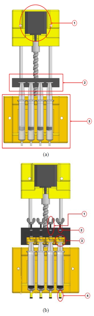
Comparison of the multi-pipetting modules: (a) previous module [21]: (1) stepper motor; (2) driving plate; (3) syringe barrel holder; (b) present module with integrated syringe calibration mechanism: (1) bolt; (2) nut; (3) hook; (4) adapter.
Although this configuration successfully realized synchronized liquid handling, it lacked a mechanism for independently adjusting the initial position of each syringe plunger. Consequently, assembly tolerances and installation errors could produce differences in the effective plunger stroke among the syringes, resulting in non-uniform aspiration and dispensing performance.
To eliminate this limitation, an integrated mechanical syringe calibration mechanism was incorporated into the multi-pipetting module, as shown in Figure 3(b). While preserving the simultaneous driving concept of the previous design, the modified driving plate enables independent adjustment of the initial position of each syringe plunger before operation.
Each syringe plunger is connected to an adjustment hook attached to a threaded bolt. The bolt engages with a fixed nut embedded in the driving plate. Rotating the bolt produces controlled axial displacement through the screw–nut mechanism, thereby adjusting the vertical position of the corresponding hook. Because each hook directly supports an individual syringe plunger, the initial plunger position can be independently calibrated without affecting the remaining syringes. Once the desired position is established, the threaded engagement mechanically locks the adjustment, ensuring stable positioning throughout repeated dispensing cycles.
As a result, the proposed module preserves the synchronized actuation of four syringes while enabling individual calibration of plunger stroke, thereby improving dispensing consistency among the four syringes. Furthermore, an adapter was incorporated between each syringe tip and the disposable pipette tip to provide stable mechanical engagement during both tip attachment and ejection.
Automated pipette-tip handling was achieved using the tip-rack holder and pipette-tip ejection unit illustrated in Figure 1(b). The tip-rack holder securely positions disposable pipette tips, allowing the pipetting module to attach a tip through a simple downward motion along the Z-axis.
Following aspiration and dispensing, the used pipette tips are automatically removed by the pipette-tip ejection unit mounted on the frame. The unit incorporates a groove-shaped retaining structure that captures the pipette tip when the pipetting module moves to the ejection position. During the subsequent upward movement of the Z-axis, the syringe body passes through the groove while the pipette tip is held in place, resulting in automatic separation from the syringe.
Because both attachment and ejection are accomplished solely through coordinated horizontal and vertical motions of the CNC platform, the mechanism eliminates the need for dedicated actuators, thereby simplifying the mechanical design while maintaining reliable tip handling.
The plate-handling subsystem comprises a double-rotary-gate plate dispenser and an automatic plate organizer, enabling continuous plate feeding and collection during automated operation.
As illustrated in Figure 4, the separating gate supports the stacked well plates while isolating the bottom plate from the remaining stack. Subsequently, the releasing gate rotates to transfer the separated plate onto the conveyor belt. The alternating operation of the two rotary gates prevents multiple plates from being discharged simultaneously, thereby ensuring reliable single-plate feeding throughout continuous operation.
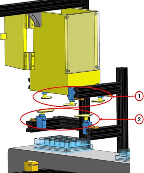
Double rotary gate mechanism of the plate dispenser showing the separating gate (1) and releasing gate (2)
Following dispensing, processed plates are transported to the automatic plate organizer, which consists of three vertically stacked storage shelves driven by a lead-screw mechanism. Absolute-coordinate positioning is employed to align each shelf precisely with the conveyor height, allowing seamless transfer of well plates without manual intervention.
The automatic plate organizer, shown as component 6 in Figure 1, was installed at the downstream end of the conveyor system to sequentially collect processed well plates. The organizer consists of three vertically arranged shelves, each capable of accommodating three well plates, resulting in a maximum storage capacity of nine well plates. The shelf assembly is driven by a lead-screw-based vertical positioning mechanism that accurately aligns each shelf with the conveyor outlet during operation. This configuration enables continuous plate collection without interrupting the dispensing process, thereby supporting long-duration unattended operation.
Variations in conveyor transport can produce positional deviations of approximately ±20 mm before the well plate reaches the dispensing station. Such deviations may cause misalignment between the pipette tips and the target wells, potentially resulting in dispensing errors or collisions with the well walls.
To compensate for these positional variations, a vision-based real-time position correction system was developed. As shown in Figure 1(b), a camera was mounted above the automatic plate organizer at an inclination of approximately 30° to continuously monitor the well plate immediately before dispensing.
Well-plate detection was performed using a YOLOv5 object detection model fine-tuned with well-plate images captured from the experimental setup. The captured images were manually labeled with bounding boxes so that the model could detect the incoming well plate on the conveyor. From the detected bounding box, the lower-center point of the well plate was extracted and used as the reference feature for position estimation. In this study, the YOLOv5 model was used as a task-specific plate-detection module rather than as a general-purpose object detector. Therefore, the practical adequacy of the detection process was evaluated through the end-to-end alignment success test rather than by reporting general object-detection metrics.
The extracted lower-center point was compared with a predefined reference coordinate corresponding to the ideal dispensing position in the CNC absolute-coordinate system. This reference coordinate was experimentally determined by aligning the pipette tips with the centers of the target wells and identifying the corresponding pixel coordinate in the camera image. Because the detected lower-center point of the well plate does not coincide with the physical well centers where the pipette tips must be inserted, a fixed geometric offset was required to transform the detected feature point into the actual dispensing target position.
Within the limited operating range of the dispensing station, the relationship between image-space displacement and the corresponding CNC compensation distance was observed to be approximately linear during the calibration procedure. Therefore, a first-order regression model was adopted as a practical compensation model for real-time position correction:
| (1) |
where Δyimg represents the pixel displacement of the detected lower-center point of the well plate relative to a predefined image-coordinate reference position established during calibration. Importantly, this reference position corresponds to the location of the detected lower-center point when the well plate is positioned such that the pipette tips are aligned with the centers of the target wells. ∆ YCNC denotes the corresponding CNC displacement applied to the plate in the transport direction.
The intercept term of 5.175 mm represents the fixed geometric offset between the detected lower-center point and the actual well-center dispensing position. Thus, the CNC compensation calculated from Equation (1) consists of two components: the displacement required to compensate for the deviation of the detected lower-center point from its calibrated reference position, and the fixed geometric offset required to locate the target well center relative to the detected lower-center feature. Accordingly, when Δyimg=0, the variable displacement component is zero, while the fixed 5.175-mm geometric offset remains necessary to transform the detected lower-center position into the corresponding well-center dispensing position.
Because the plate geometry, camera mounting position, and conveyor path were fixed throughout the experiments, this geometric offset was treated as a constant under the tested operating conditions. Therefore, Equation (1) should be interpreted as an experimentally calibrated relationship between the image displacement of the detected lower-center feature and the total CNC compensation distance, rather than as a direct mapping between the pipette-tip displacement and the CNC displacement.
The calculated compensation value is transmitted to the CNC controller before dispensing and applied to modify the original dispensing coordinates in real time. Consequently, conveyor-induced plate misalignment is effectively compensated, thereby improving the alignment accuracy between the pipette tips and the centers of the target wells.
In the present system, the correction model mainly compensated for displacement along the conveyor transport direction. Lateral displacement and in-plane rotation were not included because the conveyor guide mechanically constrained the plate orientation and lateral motion, and the dominant misalignment occurred along the transport direction. Extension to two-dimensional translation and rotation compensation will be considered in future work.
3. Experimental Methods
This section describes the experimental procedures employed to evaluate the performance of the proposed automated multi-pipetting workstation. The evaluation focused on five key aspects of system performance: (i) CNC X–Y positioning accuracy, (ii) repeatability of the electronic balance used for gravimetric measurements, (iii) dispensing accuracy following mechanical syringe calibration, (iv) liquid stability during plate transportation and stacking, and (v) the effectiveness of the vision-based position correction system. An overview of the experimental conditions and evaluation criteria is summarized in Table 1.

Summary of experimental methods and evaluation metrics
3.1 CNC X–Y Axis Positioning Accuracy Test
The positioning performance of the CNC motion platform was evaluated to determine the maximum travel speed capable of satisfying the allowable positioning tolerance of ±0.5 mm. This tolerance was established based on the positional accuracy required for reliable pipette-tip attachment and ejection, where excessive positioning errors may prevent proper press-fitting of the pipette tips or accurate alignment with the ejection mechanism.
The allowable positioning tolerance of ±0.5 mm was selected based on the geometry of the 24-well plate and the clearance between the pipette tips and the wells. Since the well diameter of the 24-well plate used in this study was approximately 18 mm, the radial clearance available for pipette-tip insertion was much larger than the measured positioning error, even when the outer diameter of the pipette tip was considered. Therefore, maintaining the positioning error within ±0.5 mm was sufficient to prevent contact between the pipette tips and the well walls under the tested conditions.
Positioning accuracy was measured using the laser pointer and grid-paper method adopted in the previous study [21]. A laser pointer was mounted on the pipetting module, and the deviation between the target travel distance and the measured arrival position indicated by the laser was measured on grid paper. Although the mechanical workspace of the CNC platform was identical to that of the previous prototype, the travel distances and operating speeds were redefined to reflect the operating conditions of the fully automated workstation.
The target travel distances were set to 130 mm along the X-axis and 115 mm along the Y-axis. Four travel speeds (72, 75, 78, and 81 mm/s) were evaluated for the X-axis, whereas three speeds (66, 75, and 84 mm/s) were examined for the Y-axis. For each operating condition, 100 repeated positioning trials were conducted. Positioning error was calculated as the difference between the target and measured arrival positions and is reported as the mean ± standard deviation.
3.2 Measurement Equipment Reliability Verification Test (Balance Repeatability)
Prior to evaluating dispensing accuracy, the repeatability of the electronic balance used for gravimetric measurements was verified to quantify measurement uncertainty. Because dispensing performance was assessed based on dispensed mass, it was essential to determine the intrinsic variation of the measurement system before evaluating the liquid-handling performance.
Four collection containers were prepared and designated as Containers 1–4. The four syringes in the multi-pipetting module were labeled as Syringes 1–4 according to their fixed positions, and each container was permanently assigned to the corresponding syringe throughout the experiments.
The empty mass of each container was measured 30 times under identical environmental conditions. The average empty mass was subsequently used as the tare value for calculating dispensing mass. Dispensed mass was obtained by subtracting the corresponding tare value from the total measured mass after dispensing. The repeatability of the balance was evaluated using the mean, standard deviation, and coefficient of variation of the repeated measurements.
3.3 Dispensing Accuracy Test (Calibrated)
The dispensing performance of the proposed system was evaluated after applying the mechanical syringe calibration mechanism. The objective of this experiment was to verify whether all four syringes could consistently dispense the target mass of 1.00 g. Based on the balance repeatability determined in Section 3.2, the allowable dispensing error was defined as ±0.10 g.
Before testing, the initial plunger position of each syringe was individually calibrated using the integrated mechanical calibration mechanism to equalize the effective plunger stroke. Subsequently, all four syringes simultaneously dispensed liquid into their corresponding collection containers. Dispensed mass was determined gravimetrically by subtracting the pre-measured tare value of each container from the measured total mass after dispensing.
Two dispensing speeds (5 and 10 mm/s) were evaluated, and 50 repeated trials were conducted for each operating condition. To minimize the influence of residual liquid accumulation, disposable pipette tips were replaced after every six dispensing cycles. Dispensing performance was evaluated using the mean dispensed mass, standard deviation, and absolute error relative to the target dispensing mass for each syringe.
3.4 Single-Well Maximum Filling Ratio Test
The maximum allowable liquid filling ratio was experimentally determined to ensure stable plate transportation and storage without overflow. During automated operation, transient plate inclination generated by conveyor movement and minor impacts during plate stacking may increase the likelihood of liquid spillage. Therefore, identifying a safe filling limit is essential for reliable automated operation.
The maximum liquid capacity of a single well (3.5 g) was defined as 100% filling. Five filling conditions corresponding to 57% (2.00 g), 60% (2.10 g), 63% (2.20 g), 66% (2.30 g), and 71% (2.50 g) of the maximum capacity were investigated. Twenty repeated trials were performed for each condition. The outcome of each trial was classified as successful ("O") when no overflow occurred during plate transport and stacking and unsuccessful ("X") when overflow was observed. The success rate was subsequently calculated for each filling condition.
3.5 Position Correction Performance Test
The effectiveness of the vision-based position correction system was evaluated by measuring the alignment success rate between the pipette tips and the target well centers during repeated automated operation.
Two operating modes were investigated: vision correction disabled (OFF) and vision correction enabled (ON). For each mode, 100 consecutive automated dispensing cycles were performed. The 100-cycle alignment test was conducted after the coordinate transformation model had been established and was not used to derive Equation (1). During each test cycle, the incoming well plate was detected independently, the displacement from the reference point was calculated, and the corresponding CNC compensation distance was applied before pipette-tip insertion.
During each cycle, the system automatically executed pipette-tip attachment, reagent aspiration, and movement to the dispensing station. When position correction was enabled, the vision system detected the current position of the incoming well plate and calculated the image-coordinate displacement Δy_img relative to the predefined reference position. The detected displacement was converted into the corresponding CNC compensation distance ΔY_CNC using the regression model presented in Section.
2.3.6. The calculated compensation value was then applied to update the dispensing coordinates before pipetting
After coordinate correction was applied, the CNC platform executed the programmed insertion motion of the four pipette tips toward the target wells. A trial was considered successful when all four pipette tips were inserted into their respective wells without contacting the well walls or plate surface. Conversely, a trial was classified as unsuccessful if any pipette tip contacted the well wall or plate surface. The alignment performance of the proposed vision-based correction system was quantified using the percentage of successful dispensing cycles.
4. Experimental Results and Discussion
This section presents the experimental results obtained to validate the performance of the proposed automated multi-pipetting workstation and discusses their engineering significance. The performance of the system was evaluated in terms of CNC positioning accuracy, repeatability of the gravimetric measurement system, dispensing accuracy following syringe calibration, liquid stability during automated plate handling, and the effectiveness of the vision-based position correction system. The results are quantitatively analyzed and compared with those of the previous prototype where applicable to demonstrate the improvements achieved through the proposed system.
4.1 CNC X–Y Axis Positioning Accuracy Test
The positioning accuracy of the CNC motion platform is presented in Figures 5 and 6. The dashed curves represent estimated reference values derived from the positioning errors reported for the previous CNC-based prototype [21]. Because the previous study employed different travel distances and operating speeds, the reported positioning errors were converted to millimeters and interpolated, or extrapolated where necessary, with respect to travel distance and velocity. Consequently, the dashed curves serve as reference estimates rather than direct experimental measurements under identical conditions.
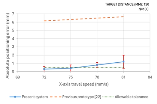
Comparison of X-axis positioning error between the present system and the previous prototype [21]
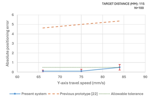
Comparison of Y-axis positioning error between the present system and the previous prototype [21]
For the X-axis, the mean positioning error was 0.3 ± 0.3 mm at a travel speed of 72 mm/s, satisfying the allowable tolerance of ±0.5 mm. Increasing the travel speed to 75 mm/s resulted in a slight increase in positioning error (0.4 ± 0.4 mm), while the mean error remained below the allowable tolerance. However, positioning performance deteriorated rapidly at higher travel speeds. The mean positioning error increased to 0.8 mm at 78 mm/s and further increased to 1.2 ± 0.8 mm at 81 mm/s, indicating that both positioning accuracy and repeatability were adversely affected under high-speed operation.
A similar tendency was observed along the Y-axis. Mean positioning errors of 0.1 ± 0.1 mm and 0.1 ± 0.2 mm were obtained at travel speeds of 66 mm/s and 75 mm/s, respectively, demonstrating excellent positioning stability. When the speed was increased to 84 mm/s, the mean positioning error reached 0.5 mm, corresponding to the upper limit of the allowable tolerance, with increased variability.
Because the previous prototype was not tested under the exact same travel distances and speed conditions, the previous prototype curves shown in Figures 5 and 6 should be interpreted as interpolated or extrapolated reference estimates rather than direct experimental measurements under identical conditions. Therefore, the comparison was used only to indicate the relative trend in positioning performance. At the common operating speed of 75 mm/s, the estimated positioning errors of the previous prototype were approximately 6.3 mm along the X-axis and 5.0 mm along the Y-axis, whereas the proposed workstation achieved mean errors of 0.4 mm and 0.1 mm, respectively. Although this comparison is not a direct one-to-one experimental comparison, the results suggest that the proposed system substantially improved positioning accuracy while maintaining the low-cost CNC-based architecture.
The improvement can be attributed primarily to the incorporation of repeatable homing using end-stop switches and the implementation of microstepping control, both of which increased positioning resolution while preserving the original mechanical architecture. Based on these results, 75 mm/s was selected as the maximum recommended travel speed because it simultaneously satisfied the positioning accuracy requirements of both axes.
4.2 Measurement Equipment Reliability Verification Test
The repeatability of the electronic balance is summarized in Figure 7. The mean masses of Containers 1–4 were 2.28 g, 2.28 g, 2.29 g, and 2.28 g, respectively, indicating excellent consistency among the measurement containers.
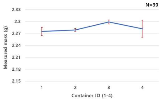
Mean ± standard deviation of container mass obtained from 30 repeated measurements
Repeated measurements produced maximum variations of 0.04 g, 0.02 g, 0.03 g, and 0.07 g for Containers 1–4, respectively. The relatively larger variation observed for Container 4 was likely associated with the intrinsic repeatability limit of the electronic balance, minor differences in the contact condition between the container bottom and the balance pan, or slight variation in container placement during repeated measurements. Although the exact cause could not be isolated, the largest observed variation of 0.07 g was adopted as a conservative estimate of the measurement uncertainty. This uncertainty was subsequently incorporated into the interpretation of the dispensing experiments. Therefore, dispensing mass differences smaller than 0.07 g were interpreted with consideration of measurement uncertainty rather than attributed solely to dispensing error. Because this value remained smaller than the allowable dispensing error of ±0.10 g, the measurement uncertainty was considered acceptable for evaluating the dispensing accuracy of the proposed system.
4.3 Syringe Calibration and Dispensing Accuracy Test
The dispensing performance obtained after mechanical syringe calibration is presented in Figure 8. Unlike the previous prototype [21], which evaluated only simultaneous aspiration performance, the present study quantitatively verified the actual dispensed mass of each syringe using gravimetric measurements.
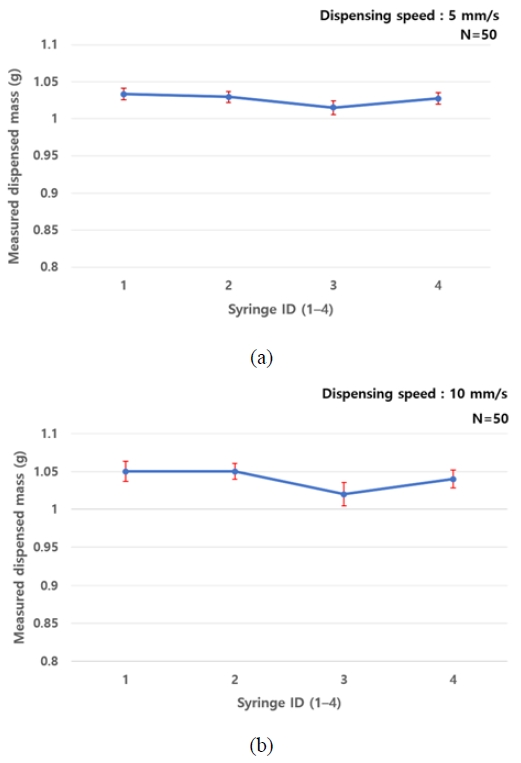
Mean ± standard deviation of dispensed mass for four syringes at dispensing speeds of (a) 5 mm/s and (b) 10 mm/s
At the dispensing speed of 5 mm/s, all four syringes consistently delivered the target dispensing mass of 1.00 g. The maximum difference in mean dispensed mass among the four syringes was only 0.02 g, substantially smaller than the allowable error of ±0.10 g. Furthermore, the standard deviation of each syringe remained below 0.01 g, demonstrating excellent repeatability and inter-syringe uniformity.
When the dispensing speed was increased to 10 mm/s, the mean dispensed masses remained close to the target value; however, a slight increase in variability was observed. The maximum inter-syringe difference increased to 0.03 g, while the standard deviations ranged from 0.01 g to 0.02 g. Although the mean dispensed masses remained within the allowable tolerance, the higher dispensing speed resulted in a modest reduction in repeatability.
Overall, the proposed syringe calibration mechanism successfully equalized the effective plunger stroke among the four syringes, enabling highly uniform dispensing performance under both operating conditions. These findings demonstrate that independent mechanical calibration effectively compensates for assembly-induced variations among syringes, thereby improving dispensing consistency during simultaneous multi-syringe operation. Considering both dispensing accuracy and repeatability, 5 mm/s was selected as the recommended dispensing speed.
It should be noted that the dispensing experiments in this study were performed at a target dispensed mass of 1.00 g using water as the test liquid. Therefore, the results primarily validate the mechanical dispensing consistency and repeatability of the proposed workstation at the milliliter scale. Although RT-PCR workflows were discussed in the Introduction as an important motivation for scalable laboratory automation, the present experiments were not intended to fully reproduce microliter-scale RT-PCR reagent handling conditions. Because RT-PCR applications typically involve smaller liquid volumes and reagents with different viscosity and surface tension, further validation using microliter-scale dispensing conditions and representative reagents or viscosity-matched surrogate fluids will be required in future work.
4.4 Single-Well Maximum Filling Ratio Test
The liquid stability experiments demonstrated that the filling ratio significantly influenced overflow during automated plate transportation and stacking. At a filling ratio of 71% (2.50 g), the success rate was only 75%, indicating that liquid overflow occurred frequently under dynamic operating conditions. Reducing the filling ratio to 66% (2.30 g) and 63% (2.20 g) improved the success rates to 90%, although occasional overflow was still observed during conveyor transport and plate stacking.
In contrast, no overflow occurred at filling ratios of 60% (2.10 g) and 57% (2.00 g), resulting in a success rate of 100% for all repeated trials. These findings indicate that a filling ratio of approximately 60% of the maximum well capacity represents a practical upper limit for reliable automated operation. Maintaining the filling ratio at or below this threshold effectively prevented overflow under the tested transport and stacking conditions.
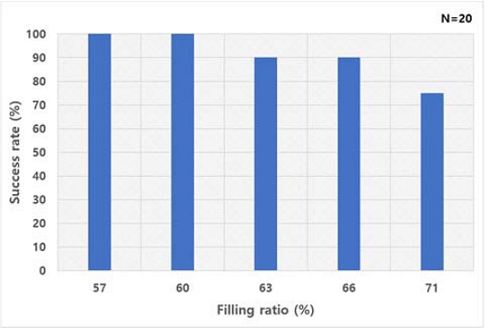
Success rate of liquid retention as a function of single-well filling ratio, where 100% filling corresponds to 3.5 g
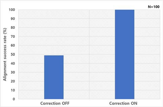
Comparison of pipette-tip-to-well alignment success rate with and without vision-based position correction
4.5 Vision-Based Position Correction Performance Test
The effectiveness of the vision-based position correction system was evaluated by comparing automated operation with the correction function disabled and enabled.
Without position correction, positional deviations of the well plate introduced during conveyor transport frequently resulted in misalignment between the pipette tips and the target wells. These misalignments caused repeated collisions with the well walls or the plate surface, and the resulting alignment success rate was limited to 49%.
When the vision-based correction algorithm was activated, the camera detected the position of the well plate and updated the CNC dispensing coordinates based on the measured plate displacement. Under this condition, the system successfully completed 100 consecutive dispensing cycles involving all four pipette tips, with no observed collisions or dispensing failures, corresponding to a 100% success rate.
These results demonstrate that the proposed vision-based compensation strategy effectively mitigated positional deviations of the well plate caused by conveyor transport. Although positional tolerances may also be introduced during the automatic pipette-tip attachment process, such tip-side positional variations were not directly measured by the vision system and were therefore not independently corrected by the proposed algorithm. Nevertheless, the 100% success rate observed during the correction-ON experiments indicates that the overall dispensing process remained robust despite the positional tolerance associated with automatic pipette-tip attachment.
Therefore, the developed position correction system provides a robust basis for reliable autonomous operation of the proposed automated multi-pipetting workstation under the tested experimental conditions.
5. Conclusion
This study presented a low-cost automated multi-pipetting workstation designed to improve laboratory automation for high-throughput liquid-handling applications. To overcome the limited accessibility of commercially available automated pipetting systems, the proposed workstation integrates a CNC-based three-axis motion platform with a mechanically calibrated four-syringe dispensing module, automated plate handling, automated pipette-tip attachment and ejection mechanisms, and a vision-based real-time position correction system. By combining these subsystems within a unified control framework, the developed workstation enables fully automated execution of the complete liquid-handling workflow while maintaining the economic advantages of a CNC-based architecture.
The experimental results demonstrated the effectiveness of the proposed system from multiple perspectives. The CNC motion platform maintained positioning accuracy within the allowable tolerance of ±0.5 mm at travel speeds of up to 75 mm/s, satisfying the positional requirements for reliable pipette-tip handling and well alignment. The integrated syringe calibration mechanism enabled all four syringes to consistently achieve the target dispensing mass of 1.00 g within the allowable error of ±0.10 g, thereby significantly improving dispensing uniformity. In addition, the vision-based position correction system successfully compensated for conveyor-induced plate displacement, increasing the pipette-tip-to-well alignment success rate from 49% without correction to 100% with real-time coordinate compensation. These results demonstrate that the proposed workstation provides accurate positioning, reliable dispensing, and robust automated operation under repetitive laboratory conditions.
The practical advantages of the proposed system were further confirmed through throughput analysis. Under fully automated operation, the workstation processed nine consecutive 24-well plates in approximately 28.3 min. The automated cycle included plate supply, conveyor transport, pipette-tip attachment, reagent aspiration, vision-based position correction, dispensing, tip ejection, and automated plate collection. Based on this measured cycle time, the automated throughput was calculated to be approximately 19.1 well plates per hour, corresponding to approximately 458 plates during continuous 24-hour operation.
For comparison, the manual baseline was estimated using the same 24-well dispensing task under continuous 24-hour operation with three operators working in rotation. The manual workflow included pipette-tip handling, aspiration, dispensing, and plate replacement. Based on the average manual processing time required for one plate, the manual throughput was estimated to be approximately 10.0 plates per hour, corresponding to approximately 241 plates during 24-hour operation. Therefore, the proposed system achieved an approximately 1.9-fold increase in throughput compared with conventional manual pipetting. In addition, because the automated workflow required operator intervention only for consumable loading, liquid preparation, and collection of processed plates, the operator-attended time was reduced by more than 20-fold compared with the continuously attended manual workflow.
Although the present study focused on a four-syringe system for 24-well plates, the proposed architecture provides a flexible platform for future expansion. Future work will include adaptation to 96-well plate formats, extension of the dispensing range to microliter-scale liquid handling, development of interchangeable adapters compatible with various pipette-tip standards, and expansion of the plate storage capacity to support long-duration unattended operation. Additional optimization of motion planning and workflow scheduling will also be investigated to further reduce cycle time and increase overall system throughput.
Overall, the proposed automated multi-pipetting workstation demonstrates that reliable laboratory automation can be achieved using a low-cost CNC-based platform without sacrificing dispensing accuracy or operational stability. By reducing operator fatigue, minimizing human-induced variability, and enabling continuous high-throughput sample processing, the developed system offers a practical and economically viable alternative to expensive commercial liquid-handling platforms. The proposed architecture is expected to facilitate broader adoption of laboratory automation in resource-limited research laboratories, educational institutions, and regional diagnostic facilities, thereby contributing to enhanced laboratory productivity, improved preparedness for future infectious disease outbreaks, and wider accessibility to automated liquid-handling technologies.
Acknowledgments
This research was funded by the Ministry of SMEs and Startups (MSS), Republic of Korea, through the Didimdol R&D Program (RS-2025-16070997), and this work includes results from a study conducted under the Regional Growth and Talent Development System (Anchor), supported by the Ministry of Education and Busan Metropolitan City (2026-ANCHOR-02-002-004).
Author Contributions
Conceptualization, M. Kim and J. Ko; Methodology, M. Kim and J. Heo; Software, M. Kim and J. Heo; Validation, M. Kim and J. Ko; Formal Analysis, M. Kim and J. Heo; Investigation, M. Kim and J. Heo; Resources, J. Ko; Data Curation, M. Kim; Writing—Original Draft Preparation, M. Kim; Writing—Review & Editing, J. Ko; Visualization, M. Kim and J. Heo; Supervision, J. Ko; Project Administration, J. Ko; Funding Acquisition, J. Ko.
References
-
K. E. Jones, N. G. Patel, M. A. Levy, A. Storeygard, D. Balk, J. L. Gittleman, and P. Daszak, “Global trends in emerging infectious diseases,” Nature, vol. 451, no. 7181, pp. 990-993, 2008.
[https://doi.org/10.1038/nature06536]

-
S. S. Morse, J. A. K. Mazet, M. Woolhouse, C. R. Parrish, D. Carroll, W. B. Karesh, et al., “Prediction and prevention of the next pandemic zoonosis,” The Lancet, vol. 380, no. 9857, pp. 1956-1965, 2012.
[https://doi.org/10.1016/S0140-6736(12)61684-5]
-
T. Allen, K. A. Murray, C. Zambrana-Torrelio, S. S. Morse, C. Rondinini, M. Di Marco, et al., “Global hotspots and correlates of emerging zoonotic diseases,” Nature Communications, vol. 8, p. 1124, 2017.
[https://doi.org/10.1038/s41467-017-00923-8]
-
V. M. Corman, O. Landt, M. Kaiser, R. Molenkamp, A. Meijer, D. K. W. Chu, et al., “Detection of 2019 novel coronavirus (2019-nCoV) by real-time RT-PCR,” Eurosurveillance, vol. 25, no. 3, p. 2000045, 2020.
[https://doi.org/10.2807/1560-7917.ES.2020.25.3.2000045]
-
J. El Hage, P. Gravitt, J. Ravel, N. Lahrichi, and E. Gralla, “Supporting scale-up of COVID-19 RT-PCR testing processes with discrete event simulation,” PLOS ONE, vol. 16, no. 7, p. e0255214, 2021.
[https://doi.org/10.1371/journal.pone.0255214]
- S. Das, A. Giri, P. Dutta, et al., “Strategies for scaling up SARS-CoV-2 molecular testing during the COVID-19 pandemic,” Frontiers in Public Health, vol. 9, p. 674150, 2021.
-
O. Vandenberg, D. Martiny, O. Rochas, A. van Belkum, and Z. Kozlakidis, “Considerations for diagnostic COVID-19 tests,” Nature Reviews Microbiology, vol. 19, pp. 171–183, 2021.
[https://doi.org/10.1038/s41579-020-00461-z]
- H. J. Huh, J. Kim, S. Kim, et al., “Surveillance of Coronavirus Disease 2019 (COVID-19) in clinical laboratories in South Korea,” Journal of Korean Medical Science, vol. 36, no. 44, p. e316, 2021.
-
Y. J. Kim, H. Sung, C.-S. Ki, and M. Hur, “COVID-19 testing in South Korea: Current status and the need for faster diagnostics,” Annals of Laboratory Medicine, vol. 40, no. 5, pp. 349–350, 2020.
[https://doi.org/10.3343/alm.2020.40.5.349]
-
K. Lee, “Laboratory diagnosis of COVID-19 in Korea,” Ewha Medical Journal, vol. 44, no. 1, pp. 1–10, 2021.
[https://doi.org/10.12771/emj.2021.44.1.1]
-
Y. J. Kim, H. Sung, C.-S. Ki, and M. Hur, “Response of clinical laboratories to the ongoing COVID-19 pandemic,” Annals of Laboratory Medicine, vol. 41, no. 6, pp. 519–520, 2021.
[https://doi.org/10.3343/alm.2021.41.6.519]
-
K. H. Hong, G. J. Kim, K. H. Roh, H. Sung, J. Lee, S. Y. Kim, et al., “Update of guidelines for laboratory diagnosis of COVID-19 in Korea,” Annals of Laboratory Medicine, vol. 42, no. 4, pp. 391–397, 2022.
[https://doi.org/10.3343/alm.2022.42.4.391]
-
Y. L. Jeon, S. G. Lee, E. H. Lee, S. Song, O.-J. Lee, U. Y. Go, G.-Y. Chun, H. M. Choi, and J. Y. Choi, “The experience and reflections of GC Labs as an independent clinical laboratory to the COVID-19 pandemic in South Korea,” BMC Infectious Diseases, vol. 23, art. 855, 2023.
[https://doi.org/10.1186/s12879-023-08684-0]
- M. J. L. De Souza, M. S. B. Holton, A. J. Carpenter, and M. R. Hibbs, “High-throughput automated liquid-handling and workflow development for improved efficiency and quality control,” Journal of Biomolecular Screening, vol. 11, no. 7, pp. 775–782, 2006.
- S. M. T. Hasan, L. K. Harris, and C. E. K. Hall, “A scalable high-throughput-screening (HTS)-compatible workflow for automated sample preparation and liquid-handling processes,” eLife, vol. 9, p. e52904, 2020.
- P. Kowal, M. Arras, and C. J. G. Théry, “Automated liquid handling workstation improves precision and reproducibility in nanoparticle recovery,” Journal of Nanobiotechnology, vol. 21, p. 34, 2023.
-
M. Gerner-Björksten, B. Almby, and E. S. Jansson, “Hand and shoulder ailments among laboratory technicians using modern plunger-operated pipettes,” Applied Ergonomics, vol. 25, no. 2, pp. 88–94, 1994.
[https://doi.org/10.1016/0003-6870(94)90069-8]
- G. Lippi, “Estimating the intra- and inter-individual imprecision of manual pipetting,” Clinica Chimica Acta, vol. 455, pp. 268–272, 2016.
- L. Guan, Y. Xia, and Y. Wang, “Assessing variations in manual pipetting: An under-investigated requirement of good laboratory practice,” Frontiers in Laboratory Medicine, vol. 9, pp. 1–7, 2023.
-
K. Pandya, C. A. Ray, L. Brunner, J. Wang, J. W. Lee, and B. DeSilva, “Strategies to minimize variability and bias associated with manual pipetting in ligand binding assays to assure data quality of protein therapeutic quantification,” Journal of Pharmaceutical and Biomedical Analysis, vol. 53, no. 3, pp. 623–630, 2010.
[https://doi.org/10.1016/j.jpba.2010.04.025]
-
M. Kang, M. Kim, I. Kim, and J. Ko, “Development of the automatic multi-pipette system using CNC machine,” Journal of Advanced Marine Engineering and Technology, vol. 49, no. 1, pp. 35–41, 2025.
[https://doi.org/10.5916/jamet.2025.49.1.35]