
Optimization of a fuzzy self-tuning PID control system for a marine low-flashpoint fuel supply system

Copyright © The Korean Society of Marine Engineering
This is an Open Access article distributed under the terms of the Creative Commons Attribution Non-Commercial License (http://creativecommons.org/licenses/by-nc/3.0), which permits unrestricted non-commercial use, distribution, and reproduction in any medium, provided the original work is properly cited.
Abstract
This study proposes and evaluates a fuzzy-logic-based self-tuning proportional–integral–derivative (PID) control system to stabilize the supply pressure of a marine low-flashpoint fuel supply system (LFSS) for liquefied petroleum gas (LPG). In low-flashpoint fuel systems, it is crucial to maintain the pump discharge pressure above the cargo's saturation pressure at all times; otherwise, vapor pockets can form in the supply line, potentially causing engine trips. Since the fuel valve train opening—and consequently the system's head loss—varies continuously with engine load, a fixed-gain PID controller is insufficient for maintaining stable pressure regulation across the entire operating range. To address this, we developed a hybrid fuzzy–PID architecture in which the proportional, integral, and derivative gains are adjusted in real time based on the pressure error and its rate of change, utilizing Mamdani fuzzy inference. A real-time closed-loop test platform was established by integrating an Aspen HYSYS dynamic process model, a Microsoft Excel database, and a Visual Basic for Applications fuzzy inference module. Parametric simulations demonstrated that the resolution of the fuzzy control surface has minimal impact on steady-state control error, whereas the gain search range is the key factor influencing stability and transient response. A range that is too wide can lead to sustained pressure overshoot and undershoot, whereas a well-bounded range can reduce the settling time by over ten seconds and mitigate oscillations. Under a variable-load profile (100%→50%→10%→100%), the proposed controller maintained the supply pressure within ±0.15 bar of the set point, well within the ±1 bar acceptance band. This confirms that fuzzy self-tuning PID control significantly enhances stability and responsiveness in nonlinear marine fuel supply systems.
Keywords:
Low-flashpoint fuel supply system, Fuzzy control, Self-tuning PID, Pump discharge pressure, Dynamic simulation, Marine engine1. Introduction
An engine fuel supply unit may appear to be a simple fluid-transfer device, but in service it behaves as a strongly nonlinear dynamic system. A marine fuel supply system, in particular, is continuously exposed to external sea conditions, nonlinear variations in engine load, and the temperature- and pressure-dependent properties of the fuel [1]. Maintaining a stable supply pressure under these conditions is a core requirement for system safety and reliability.
During seagoing operation, vibration, changes in fuel viscosity, and pump cavitation readily induce pressure fluctuations that can lead to combustion imbalance, loss of propulsion efficiency, and ultimately a system trip [2].
In systems that handle low-flashpoint fuels, the consequence is more severe: a momentary pressure drop allows the fuel to flash, forming gas pockets in the piping that have repeatedly been reported to cause pump damage and pressure pulsation [3]. Recent studies on ammonia-fuelled ships have likewise analysed the process design, vent control, and boil-off gas handling of low-flashpoint fuel supply systems by means of dynamic process simulation [4][5]. Conventional PID controllers are widely used across industry because of their simple structure and ease of tuning. However, fixed-gain PID control degrades frequently in marine operating environments characterized by nonlinearity, disturbances, sensor noise, and large time delays, and stable control then requires manual parameter adjustment and repeated trials [6]. This limitation has driven growing demand for control structures with greater adaptability and real-time correction capability for fuel supply systems, where nonlinearity and uncertainty dominate. Recent research on marine engine speed control has accordingly moved towards systematic tuning procedures that secure robust stability instead of repeated manual adjustment [7].
A survey of recent control-algorithm research shows that many studies still adopt the PID controller as their basic structure because of its simplicity and intuitive tuning. For nonlinear, multi-input multi-output (MIMO) systems, such as multivariable processes, however, the performance of a classical PID controller is limited; adaptability to changes in system dynamics or to disturbances is poor, and obtaining an optimal response requires iterative experimentation and parameter calibration [8]. To overcome these limitations, advanced model-based theories such as linear-quadratic (LQ) optimal control and H∞ control have been proposed [9]. Although theoretically superior in stability and robustness to noise and model uncertainty, their practical application to fuel supply lines—whose pressure characteristics are nonlinear, subject to time delays, and subject to disturbances—still requires extensive experimental calibration and condition-specific tuning.
For example, when the engine load of a marine fuel supply system changes, the fuel flow rate changes accordingly, and the pump discharge pressure responds immediately. Because pressure stability is the key performance index of a fuel supply unit, a single-input single-output PID controller alone cannot effectively regulate such complex pressure variations; a more adaptive and intelligent control structure is required to maintain pressure stability while tracking load changes.
In response, intelligent control techniques—fuzzy control, model predictive control (MPC), and adaptive neural control—have been studied actively. Fuzzy control converts empirical operating knowledge into fuzzy rules and enables stable control even for systems with large model uncertainty [10][11], while MPC maintains fast responses subject to constraints and has spread to process, automotive, and aerospace applications [12]. i-PID and MPC can be considered alternative approaches for adaptive and model-based control, respectively. In particular, MPC offers the advantage of simultaneously accounting for multiple constraints and predicted future responses; however, it requires an accurate process model and relatively high real-time computational capability. In contrast, the method proposed in this study reduces the computational burden by retrieving gain values from precomputed fuzzy control surfaces during operation, while allowing the controller gains to be updated without replacing the existing PID control block. Co-simulation studies of fuzzy PID pressure control in pump-driven hydraulic systems have reported comparable benefits over conventional PID control [13].
The main contributions of this study are as follows. First, a fuzzy logic-based gain-scheduling controller was applied to an Aspen HYSYS dynamic process model that incorporates the equipment specifications and operating conditions of an actual LPG fuel supply system. Second, a co-simulation environment was established in which the process calculation results from HYSYS and the VBA-based fuzzy control surfaces were linked through an Excel database. Third, the resolution of the fuzzy control surfaces and the search ranges of the PID gains were independently defined as experimental variables, and their effects on pressure stability and transient response were analyzed. Fourth, the capability of the proposed controller to maintain the pump discharge pressure was verified under continuously varying engine-load conditions.
Accordingly, this study focuses on maintaining stable supply pressure in a marine fuel supply system. The structures of representative control systems are analyzed, and a fuzzy-based PID control algorithm is then integrated to improve control performance. The objective is not merely to design a theoretically superior controller, but to propose a realistic pressure-control system that is consistent with the actual dynamics of the fuel supply unit. The proposed controller is implemented and quantitatively evaluated on a high-fidelity dynamic process model under load-variation and pressure-disturbance conditions, with the acceptance criterion that the supply pressure be held within ±1 bar of the target value.
2. Low-Flashpoint Fuel Supply System
2.1 System Configuration
The LPG fuel supply system considered here follows the structure shown in Figure 1, in which the fuel path from the storage tank through the service tank, double-walled piping, and fuel pumps to the engine is represented explicitly. The main equipment is summarized in Table 1.
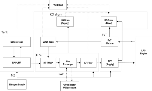
Schematic configuration of the LPG fuel supply system

Main components of the LPG fuel supply system
To satisfy the LPG supply conditions required by the MAN ME-LGI (Mechanically operated, Electronically controlled—Liquid Gas Injection) engine, a simple fuel line is insufficient; the system operates as a tightly coupled assembly of devices. LPG drawn from the storage tank is first pressurized by the LP pump and then raised to the engine demand pressure by the HP pump. Temperature is equally important: the LF heater warms the fuel to the required engine inlet temperature using glycol water, while a cooler and a glycol-water loop absorb heat when the temperature rises excessively. A recirculation line installed at the discharge of each pump returns part of the flow to the tank, maintaining constant pressure between the supply line and the storage tank, minimizing vapor generation, and accommodating sudden load changes or valve transients. Figure 2 presents the corresponding piping-and-instrumentation arrangement; Figure 3 shows the LFSS demonstration plant used to confirm that the simulated configuration reproduces an industrial installation.
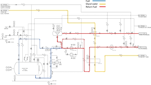
Piping-and-instrumentation diagram of the LPG fuel supply system
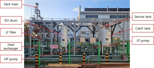
LFSS demonstration equipment
2.2 Storage and Supply Conditions
The storage conditions of the LPG in the fuel tank are listed in Table 2, and the operating conditions of the fuel delivered to the engine are summarized in Table 3. Because the tank is an IMO-independent Type-C cylindrical pressure vessel storing the cargo at ambient temperature and elevated pressure, the LP pump must transfer saturated fuel from the tank while maintaining the net positive suction head (NPSH) required by the HP pump.
LPG fuel storage condition (design basis)
LPG fuel supply condition (design basis)
2.3 Process Flow and Operation
The process flow diagram of the fuel supply system is based on the general MAN supply process. The LP pump draws fuel from the storage tank and feeds the HP pump, ensuring sufficient NPSH to prevent cavitation. The HP pump then meets the engine pressure demand. When the engine load changes, the valve opening inside the fuel valve train (FVT) changes, the head loss varies, and the supply pressure fluctuates; a fixed pump speed cannot accommodate this, so a variable-frequency drive (VFD) regulates the pump speed and, where necessary, a recirculation valve is opened to relieve excess pressure.
Fuel returning from the engine is heated to about 30 °C, raising its vapor fraction, and may be contaminated with sealing oil or nitrogen from purging. It is therefore routed not directly back to the storage tank but through a catch tank that separates impurities and vapor. Gas from the catch tank is discharged to the vent mast through a knock-out (KO) drum that retains entrained droplets. Sections that can be isolated by valves are protected by pressure safety valves (PSVs) to prevent a temperature rise in trapped liquid from overpressurizing the line. The equipment specifications are derived from a heat balance calculation for this configuration.
3. Control System Design
3.1 Pump Head–Flow Characteristics
The basic performance of a pump is expressed by the relationship between the volumetric flow rate Q and the head H. At constant rotational speed, the discharge pressure decreases progressively as the flow increases, owing to internal friction, the energy-transfer limit of the impeller, and viscous losses. This behavior is approximated by Equation (1), in which H₀ is the shut-off (zero-flow) head and K is a loss coefficient determined by the pump geometry and the fluid:
| (1) |
The shaft power P required to transfer the fluid is governed by the fluid density ρ, the gravitational acceleration g, the flow Q, the head H, and the pump efficiency η, as in Equation (2). The efficiency reaches its best-efficiency point (BEP) at a particular flow and decreases on either side of it:
| (2) |
The combined operation of the LP and HP pumps is therefore coupled to the supply-pressure control and is adjusted dynamically to the engine flow demand. In the controller design, the pump characteristic curve determines the operating point, and the resulting flow and pressure errors serve as inputs to the fuzzy control algorithm.
3.2 Pressure Control of the Fuel Supply System
Because the stored LPG is saturated, vapor can form on discharge from the tank due to heat ingress or pressure loss in the piping. The present system uses an ambient-temperature, high-pressure Type-C tank, so the LP pump must transfer saturated fuel from the tank and provide the NPSH required by the HP pump. When the engine load varies, the engine control unit (ECU) adjusts the FVT opening to regulate the fuel flow. If the discharge pressure then falls below the saturation pressure, vapor forms, control of pressure and flow in the engine gas block becomes impossible, and an engine trip may occur. Keeping the supply pressure constant is thus essential.
To this end, the controller regulates the LP- and HP-pump speeds via the VFD to maintain the discharge pressure at the engine demand value. Because the pumps are high-speed rotating machines, motor inertia limits the immediacy of speed control; when the supply pressure exceeds the demand, the controller therefore opens the recirculation valve to divert part of the flow through a bypass line and depressurize the discharge. Pump-speed control and recirculation-valve control may act sequentially or simultaneously. Surplus fuel returned from the liquid-injection engine, mixed with vapor, lubricating oil, and nitrogen, is buffered in the catch tank for impurity separation and pressure stabilization before returning to the HP-pump suction; the catch-tank pressure is held above the LP-pump discharge pressure by nitrogen through a pressure-control valve, and a level-control valve opens only above a set liquid level.
3.3 PID Control
PID control, the most widely used linear technique, drives the output using the proportional, integral, and derivative terms of the error, as in Equation (3), where u(t) is the control output mapped to the VFD speed, e(t) is the time-varying error, and Kp, Ki, and Kd are the proportional, integral, and derivative gains:
| (3) |
In the LFSS, the pump discharge pressure is the controlled variable, and the error signal is converted into a VFD speed command. Although linear PID control is widespread, it adapts poorly to the nonlinearity of the pressure–flow relationship, can overshoot when the load changes abruptly, and may lose overall stability due to interactions among control loops.
3.4 Fuzzy Self-Tuning PID Control
A fuzzy control system is a rule-based controller that mathematically models human reasoning and achieves stable control without a quantitative system model, which is advantageous for fuel supply systems subject to frequent disturbances and difficult to linearize. In the proposed controller, the input signals—the pressure error e and its rate of change Δe—are first converted into linguistic variables through fuzzification; If–Then rules are then applied in the fuzzy-inference stage; and finally, the inferred fuzzy output is converted back into a real control value through defuzzification.
Each input variable is expressed by five linguistic values, Equation (4), and each output gain by four linguistic values, Equation (5):
| (4) |
| (5) |
Here, NB, NS, ZE, PS, and PB denote negative-big, negative-small, zero, positive-small, and positive-big, while S, M, B, and VB denote small, medium, big, and very-big. The variables are represented by triangular membership functions with overlapping intervals to permit continuous control (Figures 4 and 5). Mamdani inference is used, and the rules take the If–Then form of Equation (6):
| (6) |
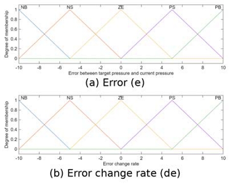
Membership functions for fuzzification of the input variables
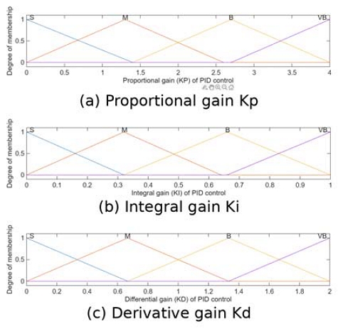
Membership functions for defuzzification of the PID gains
The rule bases are built from expert operating experience and are designed to tune the pump speed [14]. This self-tuning scheme overcomes the limitations of fixed-gain controllers by automatically adjusting gains to disturbances and changes in operating conditions. Because the inference yields multiple membership values μ, the centroid method, Equation (7), is used for defuzzification to obtain the crisp control value u*:
| (7) |
The process is regulated by independent single-loop controllers assigned to each physical quantity, to respect the distinct control characteristics of each variable and optimize stability and responsiveness. The fuzzy layer itself is a two-input, three-output gain-tuning mechanism whose inputs are the error and its rate of change and whose outputs are the three PID gains. The controller inputs are the error and its rate of change, and the simultaneous outputs are the three gains, listed in Table 4; the corresponding rule tables for Kₚ, Ki, and Kd are given in Tables 5-7.
Configuration of the fuzzy controller
Fuzzy rule base for the proportional gain Kₚ
Fuzzy rule base for the integral gain Kᵢ
Fuzzy rule base for the derivative gain Kᵈ
Gaussian membership functions provide smooth output transitions; however, they require the specification of center and variance parameters and involve exponential computations. Trapezoidal membership functions can maintain a constant membership degree over a specified interval, but they may provide reduced resolution for small error variations near the setpoint. Accordingly, triangular membership functions were selected in this study in consideration of the simplicity of control-surface generation, the ease of parameter interpretation, and their suitability for implementation in industrial controllers.
The input variables were represented by five linguistic terms: NB, NS, ZE, PS, and PB. These terms were used to distinguish among a large negative error, a small negative error, a condition near the setpoint, a small positive error, and a large positive error.
Applying five membership functions to each of the two input variables results in a total of 25 fuzzy rules. This configuration provides finer state classification than the nine-rule structure obtained using three membership functions, while reducing the design and validation burden compared with the 49-rule structure required when seven membership functions are used. Therefore, five membership functions were selected as a compromise between control resolution and rule-base complexity. A comparable trade-off between rule-base size and control resolution has been reported in variable-universe fuzzy self-tuning PID studies [15].
The fuzzy rules were established according to the following principles.
First, when the absolute value of the pressure error is large, the proportional gain (Kₚ) is set to a high value to enable a rapid return to the target pressure.
Second, in the small-error region near the target pressure, the influence of the integral gain (Kᵢ) is increased to eliminate persistent steady-state error.
Third, when a large transient error occurs, (Kᵢ) is limited to prevent overshoot and integral windup caused by excessive accumulation of the integral term.
Fourth, in regions where the error change rate is large or its sign changes, the derivative gain (Kd) is set to suppress abrupt changes in the control output and reduce oscillations.
The pump-speed command increases as the pressure error grows (direct action): when the supply pressure is below the set point, the pump speed is raised. The valve-opening command, in contrast, must close the valve as the same error grows in order to reduce pressure loss (reverse action). For identical inputs, the pump and valve operate in opposite directions, so applying the same control logic to both would cause output interference and unstable responses. An opposite-action rule set is consequently defined independently for each actuator.
In a regulatory problem where a state must be held constant, evaluating the membership functions of all rules at every sampling instant greatly increases the computational load and degrades real-time responsiveness. To resolve this, control responses are derived in advance from the error and its rate of change and stored as a rule table (the control surfaces of Figure 6). During operation, the controller does not perform full fuzzy inference at each sampling step but instead reads the stored rule directly, minimizing the computational burden while enabling delay-free, real-time control suited to a fuel supply system.
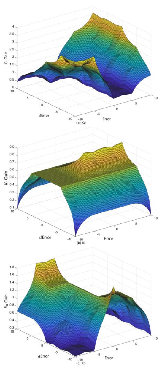
Fuzzy self-tuning control surfaces of the PID gains as functions of error and error change rate
The controller proposed in this study uses the pressure error (e) and the error change rate (Δe) as input variables to identify the current dynamic control state. The applicable gain values, including Kₚ, Kᵢ, Kd are retrieved from the control surfaces generated using fuzzy rules and membership functions and are then applied to the PID control block.
However, rather than repeatedly evaluating all fuzzy rules during operation, the proposed controller stores the precomputed fuzzy control surfaces in an Excel database and retrieves the corresponding gain values during each control cycle. Therefore, the proposed method can be more precisely classified as a precomputed lookup-table-based fuzzy gain-adjustment controller.
Compared with conventional lookup-table-based fuzzy PID controllers, the primary contribution of this study lies not in the fundamental control algorithm itself, but in its application to an Aspen HYSYS dynamic process model of a marine LPG fuel supply system. The study also analyzes the effects of control-surface resolution and PID gain search ranges and evaluates the applicability of the proposed controller to pressure regulation under varying engine-load conditions.
The fuzzy controller developed in this study does not employ an online fuzzy inference scheme in which the complete fuzzy rule base and defuzzification process are repeatedly evaluated at every sampling interval.
First, the control surfaces for Kₚ, Kᵢ, Kd are generated in advance in the VBA environment by performing fuzzification, rule evaluation, and defuzzification over the entire input ranges of the error and the rate of change of the error. The resulting control surfaces are then stored in an Excel database.
During operation, the pressure error and its rate of change calculated in HYSYS are transferred to Excel. The control gains corresponding to these input values are retrieved from the precomputed control surfaces and subsequently transmitted back to the PID block in HYSYS for application during the next sampling interval
Accordingly, the control architecture adopted in this study can be defined as a real-time gain-updating method based on precomputed fuzzy control surfaces. This approach reduces the repetitive computational burden associated with online fuzzy inference while allowing the controller gains to be adjusted according to the current operating condition without replacing the existing PID control block.
4. Simulation and Results
4.1 Main Equipment Specifications
The main equipment of the target fuel supply system and its principal design conditions are summarized in Table 8. The storage and catch tanks are IMO Type-C cylindrical pressure vessels; the LP and HP pumps are centrifugal machines whose speed is regulated by VFDs; the LF heater and cooler are indirect glycol-water shell-and-tube exchangers in which the glycol flows on the shell side and the fuel on the tube side, providing flame-free heat transfer appropriate to a low-flashpoint fuel; and the LF filter removes particles larger than 10 µm. Each pump is fitted with a disc-type non-return valve and a safety interlock that stops the pump on low power, abnormal suction pressure, or an emergency shutdown (ESD) signal.
Main components and design conditions of the LPG fuel supply system.
4.2 Closed-Loop Co-Simulation Platform
Traditional control-system development relies on open-loop testers or prototype hardware, which is costly, time-consuming, and difficult to reproduce under identical conditions. To overcome this, a virtual co-simulation platform was constructed instead of a physical rig (Figure 7). The process dynamics of the real equipment are reproduced by an Aspen HYSYS dynamic simulation, and the developed control system is coupled to it in real time so that control performance can be verified in a closed loop.
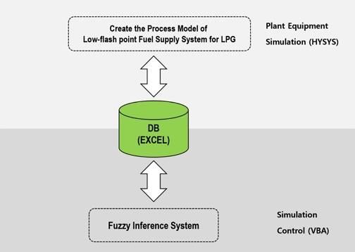
Closed-loop co-simulation architecture (HYSYS–Excel–VBA)
The fuel supply process was modeled in Aspen HYSYS Dynamic Simulation using the physical parameters of Table 8 and the Peng–Robinson equation of state. The dynamic-mode configuration, including the controller settings and the actuator response characteristics, followed established practice for dynamic process simulation in Aspen HYSYS [16]. The fuzzy-inference system was implemented in Microsoft Visual Basic for Applications (VBA) 7.1, and its output was exchanged with the HYSYS database via an Excel database, allowing control variables to be passed in real time at each sampling step. The Excel layer performs two roles: it records the error and error change rate computed from the measured pressure, temperature, and flow received from HYSYS, and it looks up the corresponding gains from the rule table and returns them to HYSYS. The simulation conditions are summarized in Table 9, and the full HYSYS process model of the 200 kW LPG fuel supply unit—comprising a fuel-supply part, a nitrogen-supply part, and a heating-medium part, each with its own feedback loop—is shown in Figure 8.
Simulation environment settings.
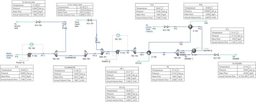
Aspen HYSYS dynamic process simulation of the 200 kW LPG fuel supply system
4.3 Parametric Case Studies
Three cases, summarized in Table 10, were used to examine how the resolution of the fuzzy control surface and the gain search range affect control performance. In all cases, the engine load was fixed at 50 %.
Definition of the simulation cases
In this study, Kₚ and Kᵢ were updated using the fuzzy control surfaces, while Kd was fixed at zero. The derivative gain was not adjusted during operation because of the possibility that rapid fluctuations in the fuel-supply pressure signal and numerical differentiation could induce oscillatory control behavior.
Case 1 used a 100 × 100 control surface with narrow gain ranges (Kₚ: 0–1, Kᵢ: 0–2). As shown in Figure 9(a), Kₚ rises sharply during the first second as the controller aggressively seeks the set point, oscillates slightly between 1 and 3 seconds as the fuzzy system reacts to the initial error, and then converges to about 0.9. The integral gain Kᵢ in Fig. 9(b) rises quickly and stabilizes near 1.7 after about three seconds without sustained oscillation, since the integral action mainly removes residual error and requires little correction once the transient has passed. The discharge pressure in Fig. 9(c) overshoots the target initially but becomes completely flat after about 5 s, confirming stable regulation within the narrow gain range.
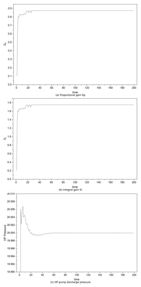
Case 1 results (resolution 100 × 100; Kₚ 0–1, Kᵢ 0–2)
Case 2 retained the 100 × 100 resolution but widened the ranges to Kₚ: 0–4 and Kᵢ: 0–500. The response became faster, but oscillation appeared in the high-gain region. As shown in Figure 10(a), the fourfold wider Kₚ range produces a much stronger initial reaction; the controller enters the high-gain region and exhibits an erratic, spiking pattern before converging as the error decreases. The greatly extended Kᵢ range in Figure 10(b) causes the integral term to be over-compensated in places, producing irregular oscillation, and the discharge pressure in Figure 10(c) shows repeated overshoot and undershoot. These results indicate that an excessively wide search range makes the controller over-sensitive and that gain-magnitude limits are necessary in practice.
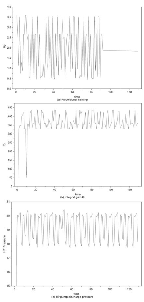
Case 2 results (resolution 100 × 100; Kₚ 0–4, Kᵢ 0–500)
Case 3 kept the wide ranges of Case 2 but lowered the resolution to 15 × 15. The fine controllability of the response curve decreased, and error oscillation appeared near the target value. As shown in Figure 11(a), low resolution produces a staircase pattern in Kₚ because the coarse fuzzy surface's input–output mapping is not smooth; a rough surface can cause abrupt changes in the output. The integral gain in Figure 11(b) is likewise more irregular and variable, and the discharge pressure in Figure 11(c) exhibits larger error and a longer settling time. These results clearly demonstrate that the surface resolution is an important design parameter, although—as the comparison with Case 1 shows—its effect on the steady-state error band is secondary to that of the search range.
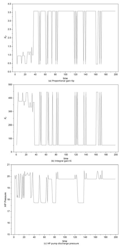
Case 3 results (resolution 15 × 15; Kₚ 0–4, Kᵢ 0–500)
4.4 Performance under variable engine load
Based on the case analysis, the baseline gains were fixed at Kₚ = 0.66 and Kᵢ = 1.32, and the engine load was varied in the sequence 100 % → 50 % → 10 % → 100 % (Figure 12(a)). The fuzzy controller compensated for load-induced pressure changes in real time and maintained a control accuracy of ±0.15 bar—substantially tighter than the ±1 bar acceptance band—even during transients (Figure 12(b)), corresponding to roughly an 85% improvement relative to the acceptance criterion. This confirms that fuzzy-PID control secures high adaptability and stability under nonlinear load variation. A residual steady-state error nevertheless appeared in the low-load region below 10 %, where fine pump and valve adjustments to move the pressure are difficult to implement; this should be addressed in future work through nonlinear compensation or adaptive-gain correction.
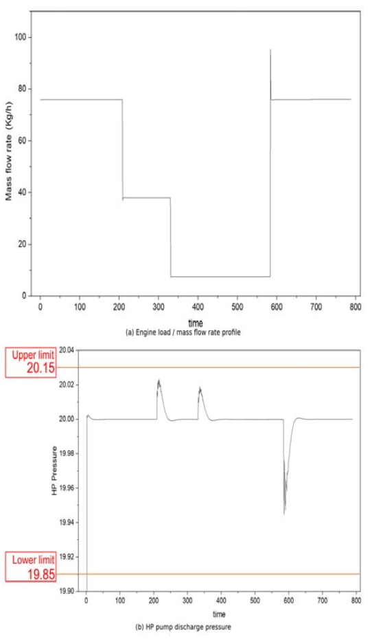
Controller performance under a variable engine-load profile
5. Conclusion
A fuzzy-based control system that regulates pump speed to maintain constant pump discharge pressure despite load-induced changes in the FVT opening was designed and verified through real-time simulation. To overcome the fixed-gain structure of conventional PID controllers and the inefficiency of condition-by-condition gain scheduling, a self-tuning PID controller using fuzzy inference was implemented; by adjusting the PID gains in real time according to the error and its rate of change, the system not only satisfied the ±1 bar acceptance band but also limited the actual control error to within ±0.15 bar.
The experiments, conducted in a real-time co-simulation environment, aimed to assess the platform's adequacy and the influence of the control-surface resolution and the gain search range. The resolution was found to have no significant effect on the control-error band: increasing it from 15 × 15 (225 rules) to 100 × 100 (10,000 rules) roughly quadrupled the computational load without a corresponding improvement in accuracy. The search range, by contrast, was the decisive factor: an excessively wide range produced repeated overshoots and undershoots and failed to hold the pressure within ±1 bar, whereas an appropriately bounded range shortened the time to reach the target pressure by more than 10 seconds and reduced the post-transient pressure variation, improving stability. The rule base and the normalization range of the input variables are thus the core design elements that govern the stability and transient response of the fuzzy controller.
Under load variation, the proposed self-tuning fuzzy-PID controller regulated the supply pressure within ±0.15 bar, an improvement of about 85 % relative to the acceptance criterion, with higher adaptability and faster response than manual PID tuning; the decentralized loop structure that adjusts the pump speed effectively suppressed load-induced pressure fluctuations. In the operating region below 10 % load, a residual steady-state error persisted, indicating the need for more refined nonlinear compensation or adaptive-gain correction. Future work will validate the soundness of the process model and the controller within this simulation environment, quantitatively compare manually tuned PID gains with the fuzzy self-tuning results to demonstrate the superiority of the fuzzy approach, and extend the control strategy to multiple operating modes (start-up, purging, standby) so that the proposed controller can serve as a standard control technology for intelligent marine fuel supply systems.
Acknowledgments
This research was supported by Korea Institute of Marine Science & Technology Promotion(KIMST) funded by the Ministry of Oceans and Fisheries, Korea(RS-2024-00410200).
Author Contributions
Conceptualization, C. H. Park and J. K. Lee; Methodology, C. H. Park and K. G. Kim; Software, C. H. Park; Formal Analysis, C. H. Park; Investigation, C. H. Park; Resources, S. M. Ji; Data Curation C. H. Park; Writing-Original Draft Preparation, C. H. Park; Writing-Review & Editing, Y. J. Cheon and S. M. Ji; Visualization, C. H. Park; Supervision, Y. J. Cheon and J. K. Lee; Project Administration, J. K. Lee; Funding Acquisition, J. K. Lee.
References
-
S. K. Hwang and B. G. Jung, “A novel control strategy on stable operation of fuel gas supply system and re-liquefaction system for LNG carriers,” Energies, vol. 14, no. 24, p. 8413, 2021.
[https://doi.org/10.3390/en14248413]

-
C. Wang, H. Xu, X. Wu, et al., “Transient performance study of high pressure fuel gas supply system for LNG fueled ships,” Cryogenics, vol. 125, no. 103510, 2022.
[https://doi.org/10.1016/j.cryogenics.2022.103510]
-
K. Milioulis, V. Bolbot, and G. Theotokatos, “Safety analysis of a high-pressure fuel gas supply system for LNG fuelled vessels,” Proceedings of the Institution of Mechanical Engineers, Part M: Journal of Engineering for the Maritime Environment, vol. 236, no. 4, pp. 1025-1046, 2022.
[https://doi.org/10.1177/14750902221078426]
-
S. -K. Jeong, Y. -T. Kim, and J. -S. Kim, “Simulation and analysis of a fuel supply system with vent control system for ammonia fueled ships,” Journal of Advanced Marine Engineering and Technology, vol. 48, no. 5, pp. 260-267, 2024.
[https://doi.org/10.5916/jamet.2024.48.5.260]
-
S. Jeong, J. Kim, and Y.-T. Kim, “Optimization study of BOG re-liquefaction process for ammonia fueled ship,” Journal of Advanced Marine Engineering and Technology, vol. 48, no. 4, pp. 167–176, 2024.
[https://doi.org/10.5916/jamet.2024.48.4.167]
-
Z. Hu, W. Guo, K. Zhou, et al., “Optimization of PID control parameters for marine dual-fuel engine using improved particle swarm algorithm,” Scientific Reports, vol. 14, no. 1, pp. 1–22, 2024.
[https://doi.org/10.1038/s41598-024-63253-y]
-
G.-B. So, G.-G. Jin, C.-H. Lee, H.-R. So, D.-J. Kim, and J.-K. Ahn, “TDOF PID controller for enhanced disturbance rejection with MS-constraints for speed control of marine diesel engine,” Journal of Marine Science and Engineering, vol. 12, no. 11, p. 2023, 2024.
[https://doi.org/10.3390/jmse12112023]
- K. J. Åström and T. Hägglund, PID Controllers: Theory, Design, and Tuning, 2nd ed., Research Triangle Park, NC: ISA, 1995.
- K. Zhou, J. C. Doyle, and K. Glover, Robust and Optimal Control, Upper Saddle River, NJ: Prentice Hall, 1996.
-
D. Driankov, H. Hellendoorn, and M. Reinfrank, An Introduction to Fuzzy Control, 2nd ed., Berlin: Springer, 1996.
[https://doi.org/10.1007/978-3-662-03284-8]
-
H. Zhang, Z. Zhao, Y. Wei, Y. Liu, and W. Wu, “A self-tuning variable universe fuzzy PID control framework with hybrid BAS-PSO-SA optimization for unmanned surface vehicles,” Journal of Marine Science and Engineering, vol. 13, no. 3, p. 558, 2025.
[https://doi.org/10.3390/jmse13030558]
-
S. J. Qin and T. A. Badgwell, “A survey of industrial model predictive control technology,” Control Engineering Practice, vol. 11, no. 7, pp. 733-764, 2003.
[https://doi.org/10.1016/S0967-0661(02)00186-7]
-
Z. Yan, G. Tang, and Y. Gao, “Research on pressure control of hydraulic system for pump controlled anchor drilling machine based on variable universe fuzzy PID algorithm,” Machines, vol. 13, no. 3,p p. 199, 2025.
[https://doi.org/10.3390/machines13030199]
-
T. Pangaribowo, et al., “Modeling of control system for hydrogen and oxygen gas flow into PEMFC based on load demand by using fuzzy controller,” International Journal of Advanced Trends in Computer Science and Engineering, vol. 9, no. 1.4, pp. 606–611, 2020.
[https://doi.org/10.30534/ijatcse/2020/8491.42020]
-
H. Li, Y. Hui, J. Ma, Q. Wang, Y. Zhou, and H. Wang, “Research on variable universe fuzzy multi-parameter self-tuning PID control of bridge crane,” Applied Sciences, vol. 13, no. 8, p. 4830, 2023.
[https://doi.org/10.3390/app13084830]
-
R. Elyas, “Dynamic simulation for process control with Aspen HYSYS,” in Chemical Engineering Process Simulation, 2nd ed., Amsterdam: Elsevier, pp. 309-341, 2023.
[https://doi.org/10.1016/B978-0-323-90168-0.00015-9]